The build is done, as of 11/29/14. Thanks to C_K for making the driver!
Two members were approached by a third member, about doing a Maglite mod. The member who contacted us was rockhound42 and the two members he approached were Cereal_Killer and I.
C_K and O-L will be modding a 2D Maglite. It will have lots of things in it... Lots of different things...
- File work on the light
- Copper heat sinks
- Nichia LEDs
- RGB LEDs
- C_K's Custom Driver
- A Charger built in the light The charger project is dead. It will just be a dummy cell. Maybe a second chance is coming.

I guess that's about it for now, so on to the start of the build...
But first, a little music
OK, let's start with the Maglite
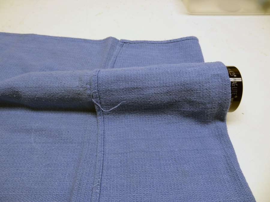
Well, you didn't think I would show the whole thing yet, did you? I've already done the file work, so I won't be showing that till the end. But, it is a Black 2D Incan Maglite.
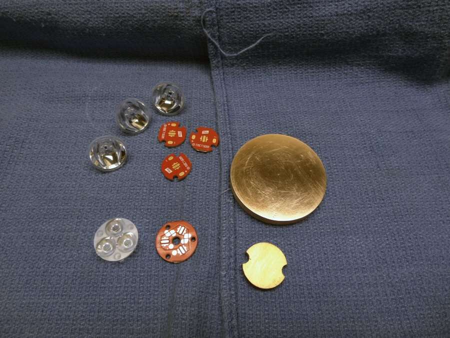
So we start with a copper heat sink that sits down in the head and a smaller copper heat sink, (the one shown is not the one I will use), for the center 3-up. Then there are some Noctigons and some TIR optics. The large heat sink is made from 5 copper discs and they were soldered together under pressure and brought down to size with the drill press and a Dremel bit. The diameter is made for a tight fit in the head and overall it came out with about 0.005" out of round, which is not perfect, but not bad for hand work either. It will have to suffice.

The 3-up has to be higher than the three outside, because of the difference in the TIR optics. It's going to be 10# of stuff in a 5# light, with all the leds and wiring, but it ought to be quite different when it's fired up. The RGB will be in the center 3-up and the Nichias on the outside.
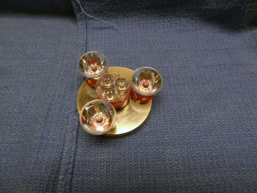
This is the idea. There's lots to do to make them fit. All the optics have to be shaved down to fit into the 50mm diameter head.

I have the leds too. XP-E for the RGB and of course, the Nichia 219s.
I have all of this in my "mind's eye". This is how I do a build. I look at it and I immediately "see" what it will be. The challenge is finding a way to make it work as I see it. That is sometimes too much for my little mind, but it keeps me going.
I have a long four day week-end, so I imagine it will all be done, except for the custom driver. C_K is working on that already, but I will let him talk about that, when he's ready to go over it with us.
---------------------------------------------------------------------------
Friday - 11-07-14
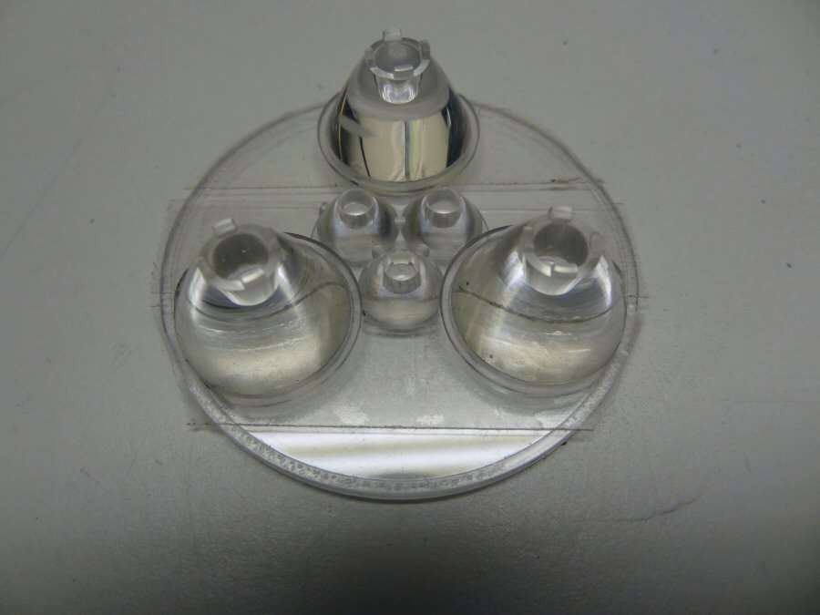
The idea for holding the TIR optics is to use a plastic Maglite lens and cut out the openings for the TIRs. The first thing I have to do, is to get them all to fit into the diameter of the lens. They have to be cut down to do that. The center 3-up has been modified, by removing the posts and sanding cut outs where they were, so the outer optics can get in closer.
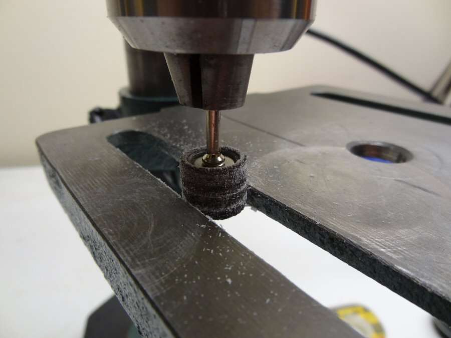
I did that with a sanding drum on the drill press.
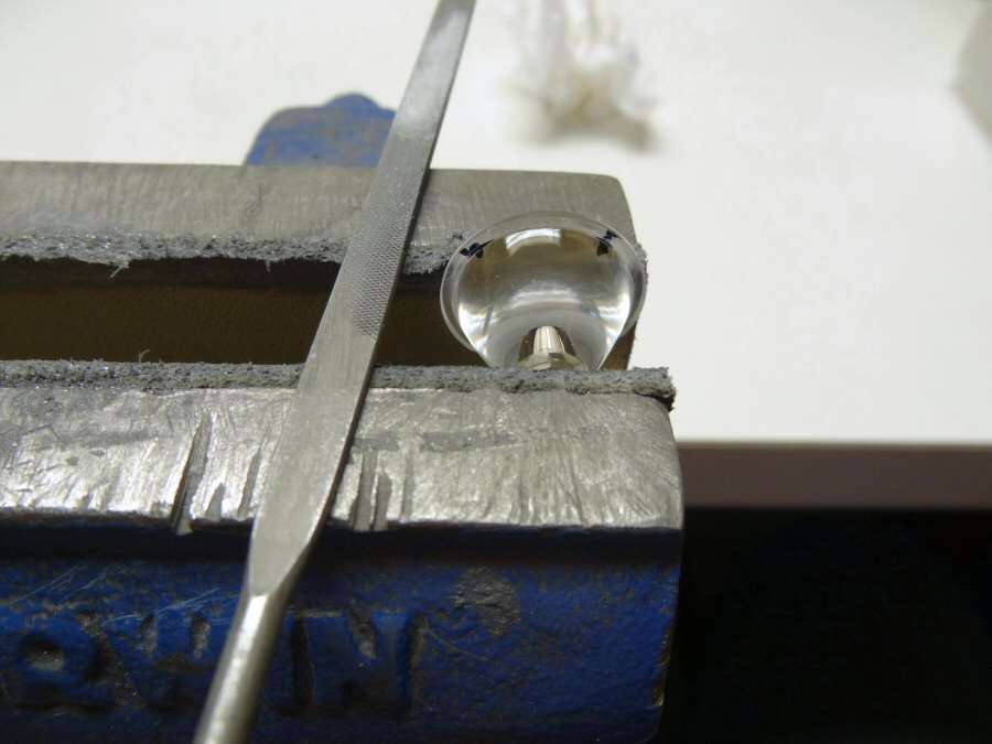
Next thing is to remove the outer lip from the three larger TIR optics, where they will touch the 3-up. I did this with a hand file.
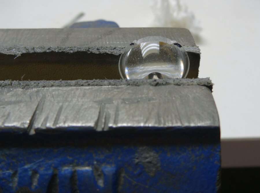

So, the optics are all shaved down and they fit in the Mag lens diameter. I have used double sided tape, so I can flip it over and mark where I will cut out the openings.
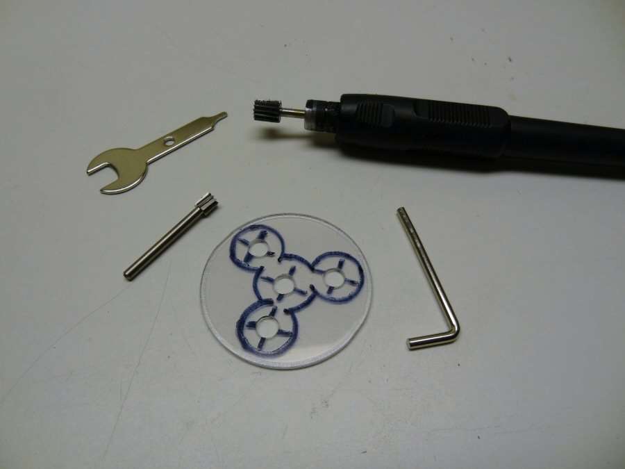
I drilled starter holes and then used the Dremel tool, to open them up.


Now everything is in place and it's time to epoxy them together.
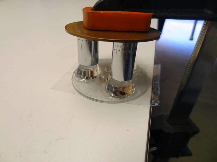
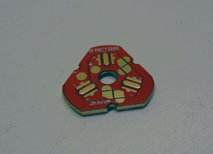
Crap! I forgot about the star and the heat sink. They won't fit in any more due to the taper of the outer TIR optics. Well, it's now a triangle shaped star and the heat sink will be too.
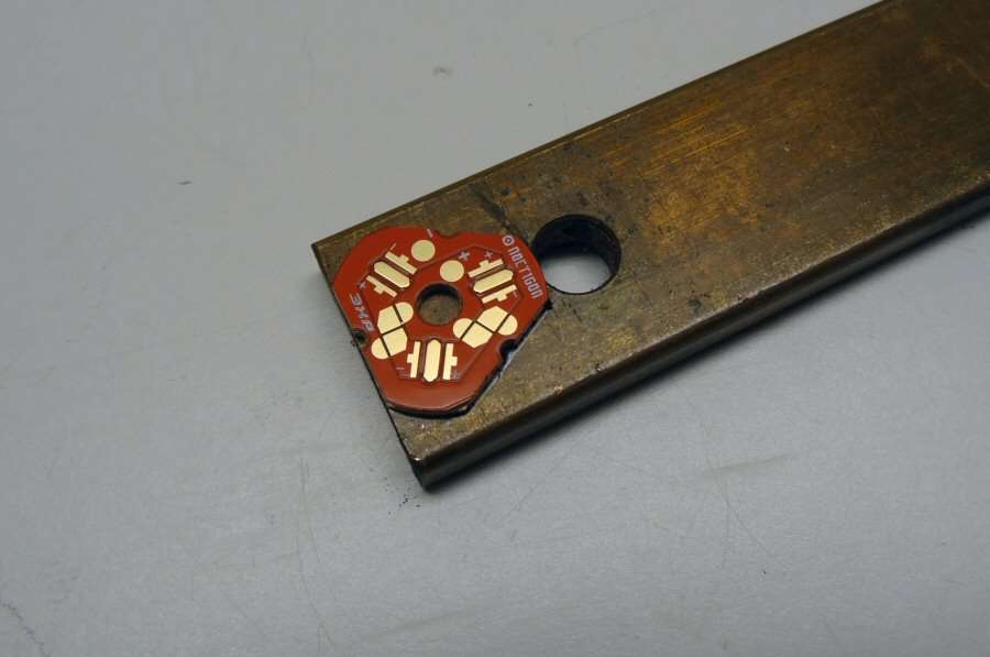
I still have a little copper bar stock that was sent to me by another member. It's just about the right thickness, so I might as well use it.

Hacksaws and files make for a nice hand made pedestal.
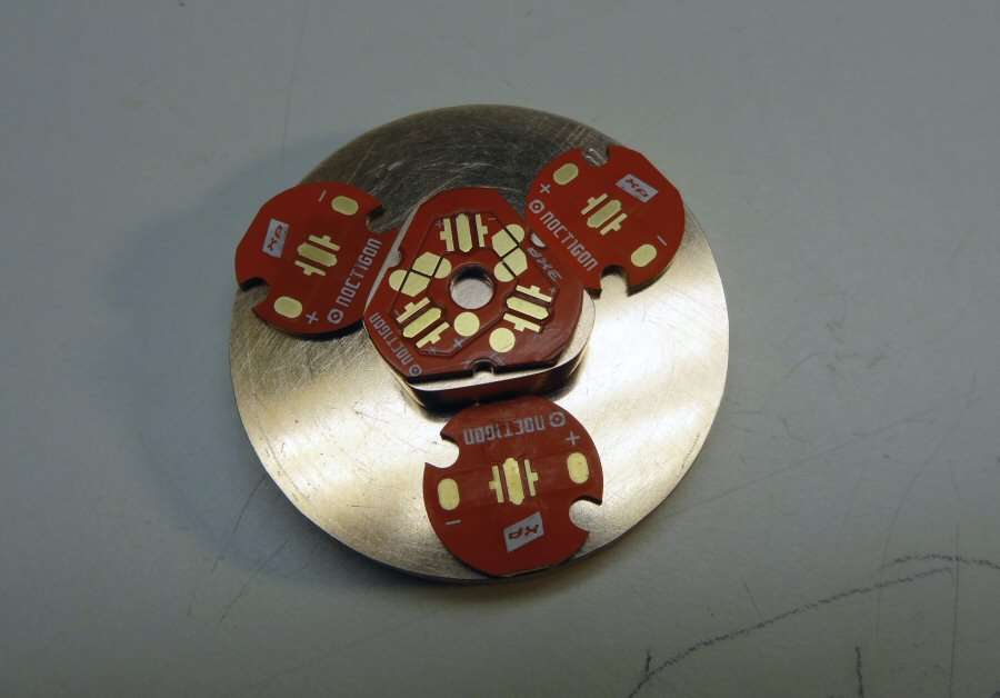

Checking the stack up, I see that the center heat sink is not tall enough, so it's time to add some sheet stock. 0.025" +or- ought to do it.
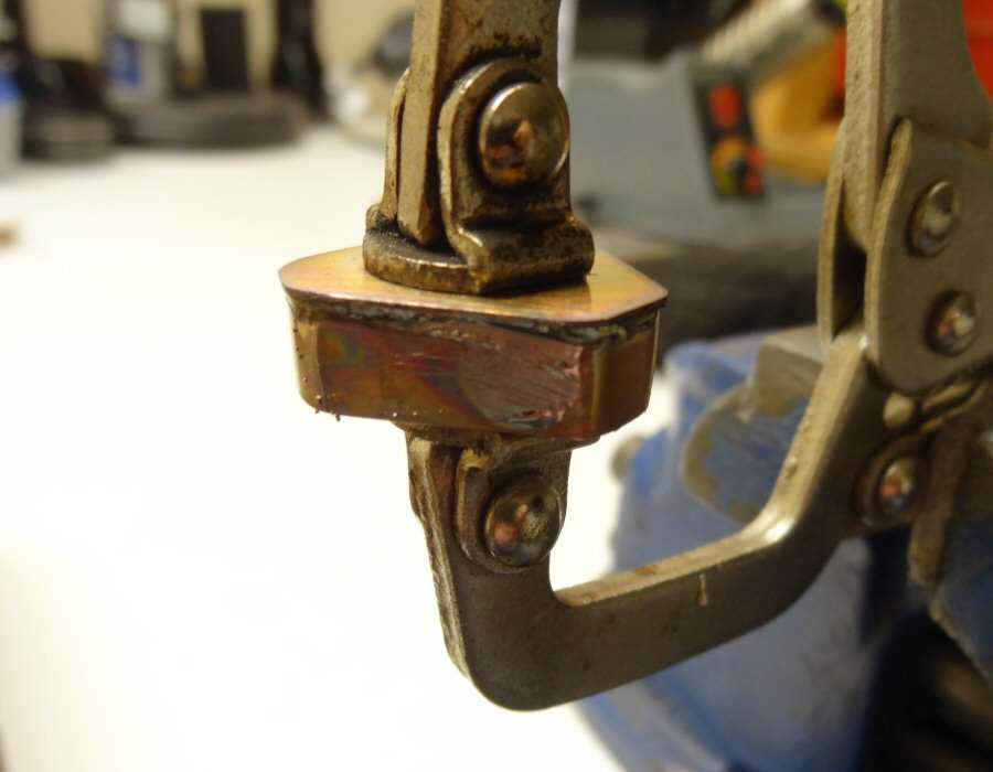
Pressure soldering the sheet stock to the heat sink.
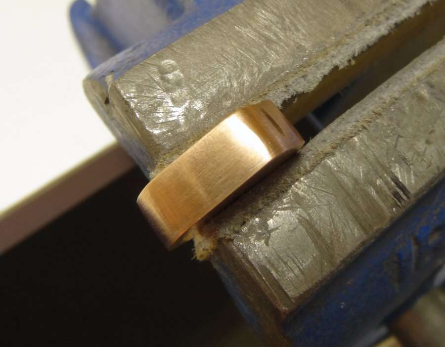
The reason I use the pressure, is to get as thin a layer of solder as possible. It makes a stronger joint and solder is not the best heat conductor, so I only want a very thin layer. If it's pressed together while soldering, the seam shouldn't hardly show.
------------------------------------------------------------------------------
That's all for now. I have been at it from 8AM till 3PM and I need a break. See y'all later.
11-07-14 7PM
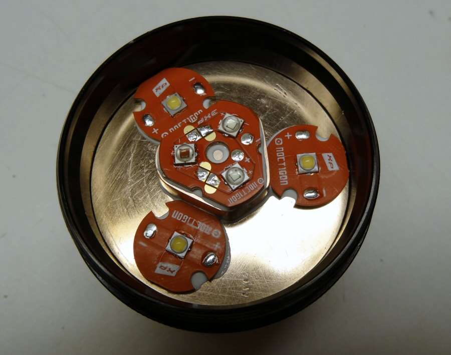
LEDs are reflowed and everything is in the head.

The stack up height was perfect. The bezel tightens down all the way. It won't stay that way, because I have to make a cover plate over that ugly plastic one. I have some brass plate. I probably will make it out of that. It's 0.050" thick, so it's good and sturdy. I just don't want to try to make it with a Dremel. Anyhow, I will probably go and work on the other end of the light for a while. Time for the battery charger project.
------------------------------------------------------------------------------------
EDIT: Finished the Brass cover for the optics.
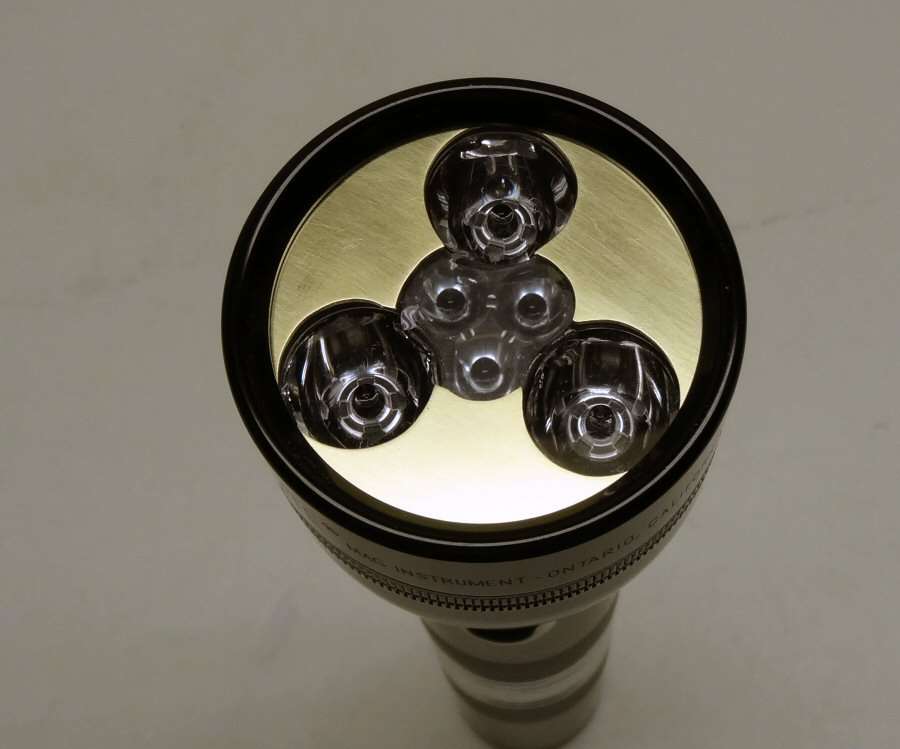
Since I will not get the light done this week-end and since I said I would show the file work, here is it. The light is going in a specific vehicle and I tried to make it something that would look like it fit in that vehicle.

I don't know what else I will work on now. Probably finish the head and run all the wires. I just can't finish the tail end now, till the parts come in.
---------------------------------------------------------------------------------
11/09/14
Finishing up the head and the battery holder, as far as I can go without the rest of the parts.
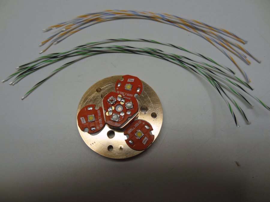
I drilled three holes for wires and three more holes for screws, to hold the heat sink down.
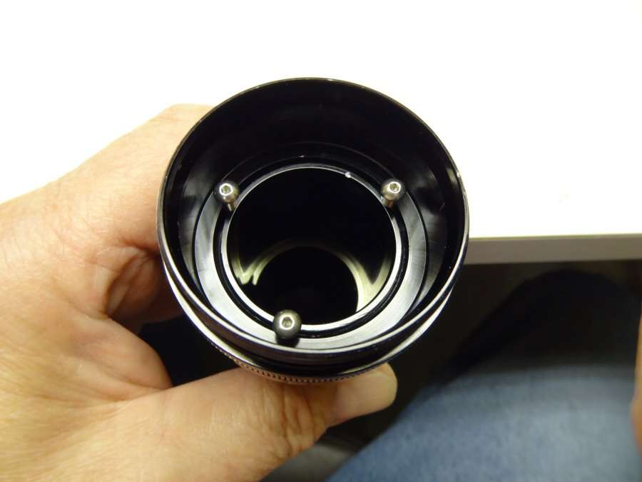
The screws go down in between the head and body. That way, the head can't be turned unless the heat sink is removed.
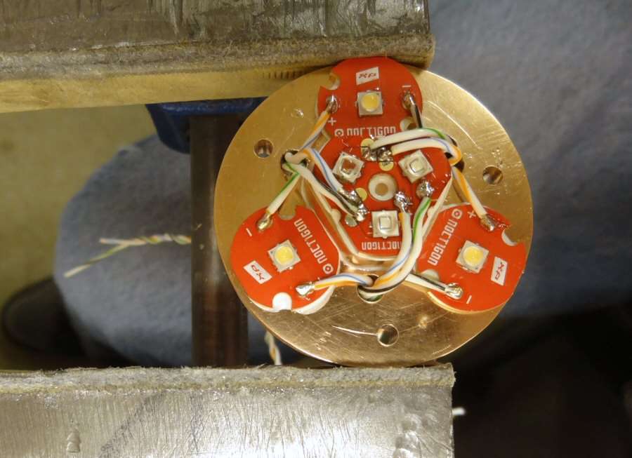
Wired up. 12 wires in all. Each led is individual. The three Nichias will end up being run parallel.
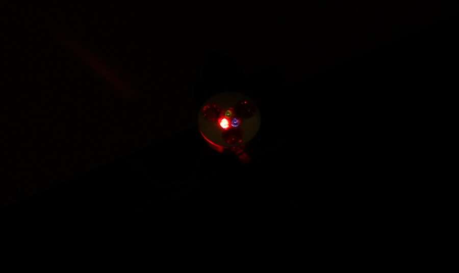
I used a 3xAAA holder and AAA Alkalines, so I wouldn't give out a lot of amps, for DD testing. Here the RGB are on, but the red overpowers the blue and especially the green. From seeing this, I would think maybe 350mA for the red, 700mA for the blue and 1050 mA for the green, to balance them out, but I know C_K already has it all under control, with the driver he is going to make.
The shots below are just the individual RGB and then the 3 Nichias.

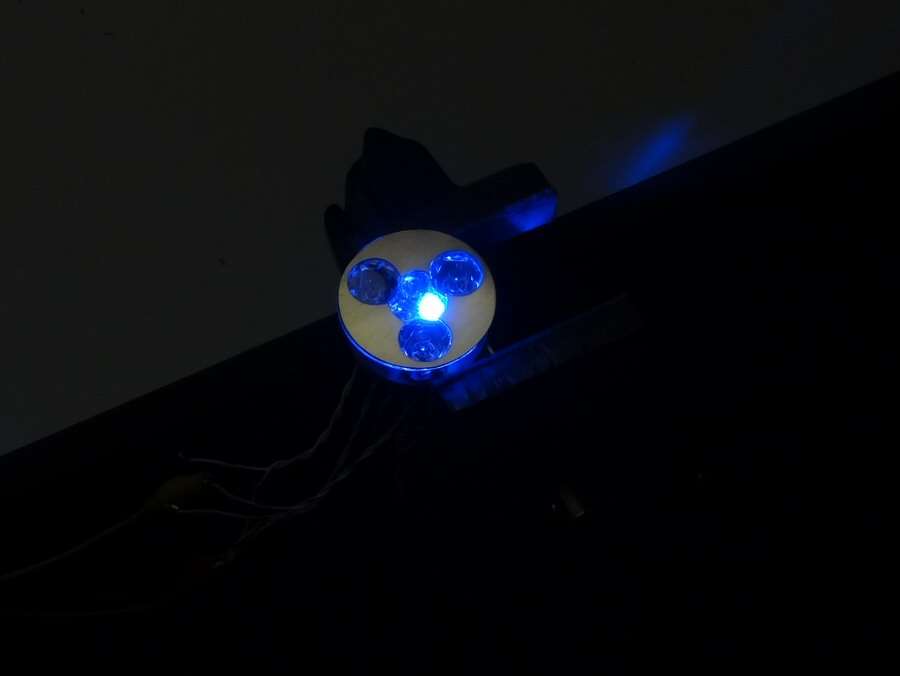
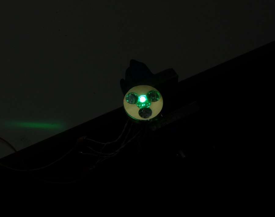

--------------------------------------------------------------------------------------------------------
The charger project is scrapped. I ended up ruining the tail cap and two charger boards, so it will just be a dummy cell. I think this dummy can make that much. The Phoenix may arise from the ashes, time will tell, but you know I just hate to be defeated, especially by myself.
---------------------------------------------------------------------------------------------------------
11-15-14
So, I just cannot stand failing on the charger. I have to try again. Of course, it's got to be more involved this time.
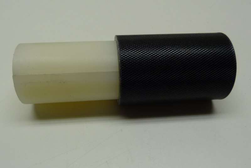
Since the tail cap was so hard, let's just make it harder and put it in the body! Well, in some ways, it will be easier. It will go in front of the cell, up against the switch housing, so wires will be easier. I had a piece of plastic rod that was a little bigger than the body of the light, so I split it and worked it down till it is a tight fit in the body.

Now the split is not centered, but some things just never go the way you plan, well most things... Actually, it will still work, because of how I will mount the USB charger.
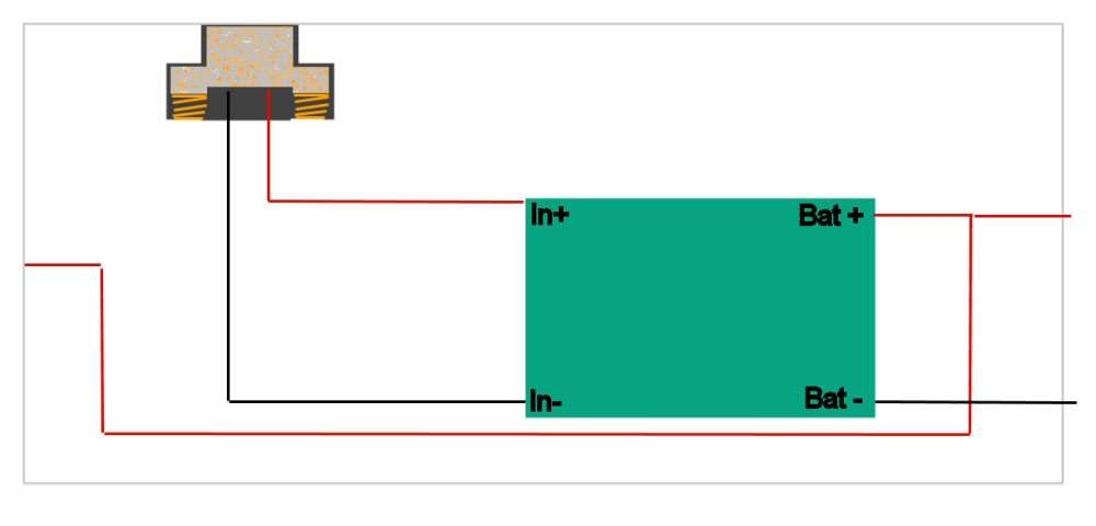
I am going to remove the USB socket off the board. I will put the USB socket up in the plastic, as shown in the photo above. The USB is in the upper left corner. I plan on making it so that I can use two small springs under the outside tabs of the socket, so it will be spring loaded. The board will go over on the bottom right and the wires are shown. I think it will work, but you know how it goes. I will not have the boards till next week, but I just had to post and say it's not over till the fat charger sings. (well I can't say fat lady or I will get in trouble, so fat charger is as close as I can go).
I decided not to separate components, but keep the board whole, see farther down the post for more info.
More when I get more...
----------------------------------------------------------------------------------------------------------------------
11-18-14
The boards came in

I got 4 of them, so I could wreck 3 and still have one left for the build.
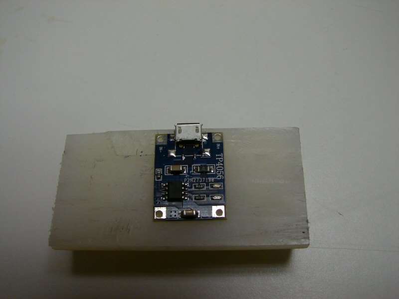
I think I can fit the whole board in, so I don't have to disassemble it.
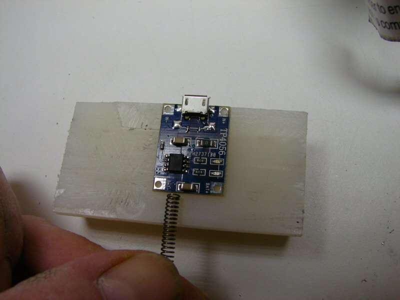
and still have room for it to be spring loaded. Maybe...

A little "mill work"
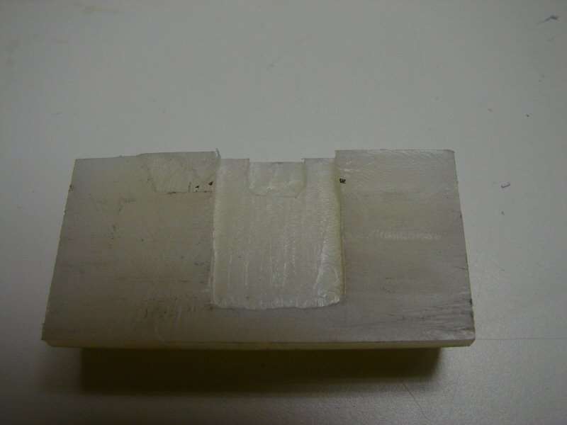
and the pocket is made for the board.
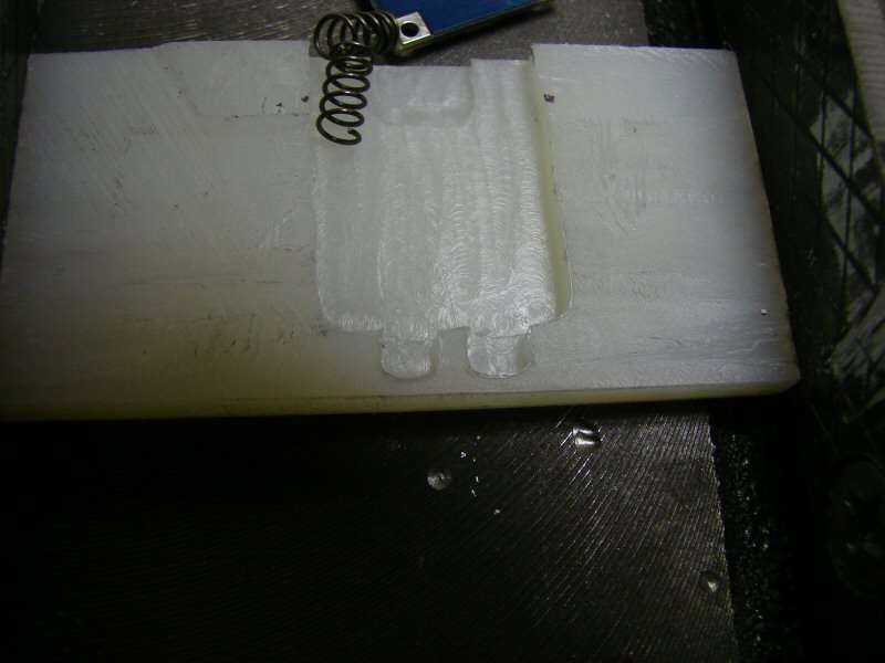
Then it's time to cut the spring holes.
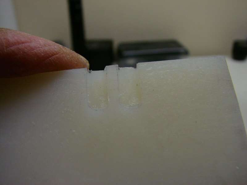
They have to be cut on the other half too.
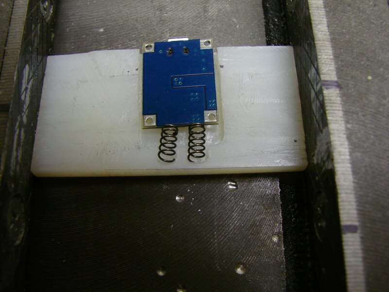
Looks like this, kinda, sorta

Bottom side

Top side, those springs push up the board and when compressed, they give quite a lot of tension. That's what I want.

It will slide inside the body tube and when in position, the USB plug should pop up in place, in the slot in the body.
Lots more to do, till it's ready. I just don't have any more time today. Time to go to work!
-----------------------------------------------------------------------
11/19/14
A little more on the charger assembly.
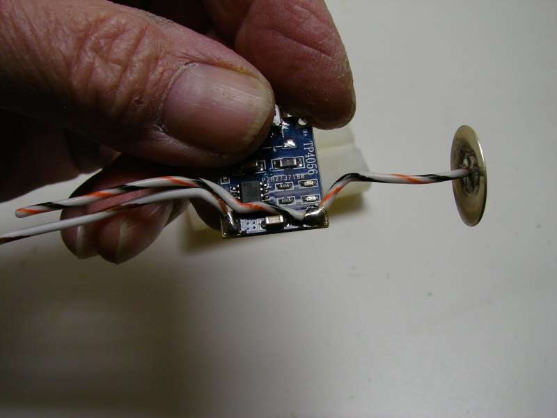
18Ga wires are in place for the +/-

That leaves the problen with the signal leds again.
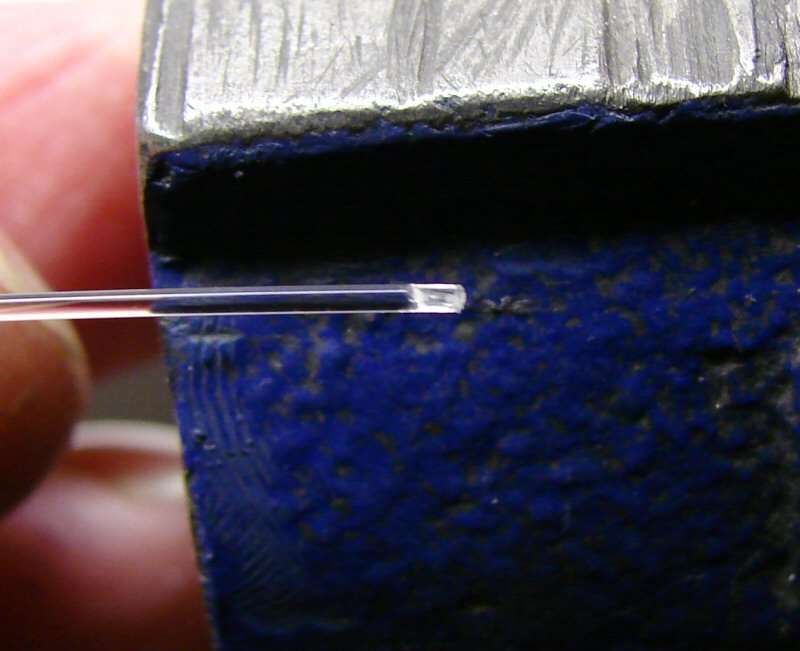
I have discovered that I can split a fiber optic down the middle, with a sharp razor blade.
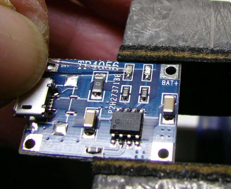
So, that will allow for the optic to lie flat on the leds and I can use them that way. What I will now play around with is making two spots in the optic, so I can lay one fiber across both leds. That way I only have to run one fiber up and thru. If it works, it will be a cleaner look on the finished light and since both leds don't come on at the same time, it shouldn't be a problem.
That's it for now. It's colder than something in February around here. Oh, I know it's only in the 20s at night, but when it's in the hundreds in the summer, the 20s are too darned cold! The garage is cold as the outside, so no relief there either.
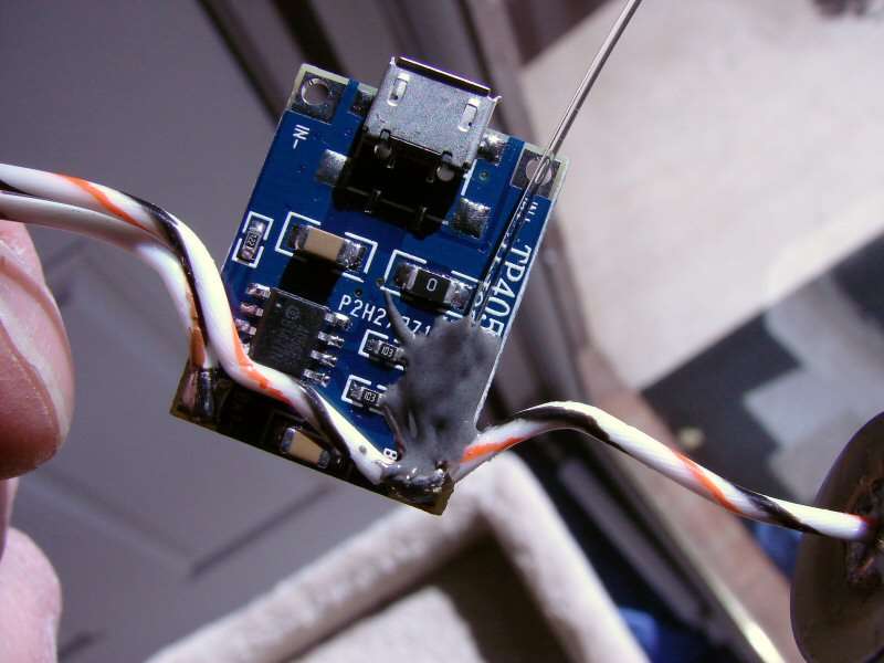
The fiber optic is in place. I used clear epoxy first and then used JB Weld over top, to contain the light and hopefully make the fiber brighter.
Now it's time to go make a hole in the body... Hope this works out.
------------------------------------------------------------------------------
11/21/14 The charger is DONE!!!
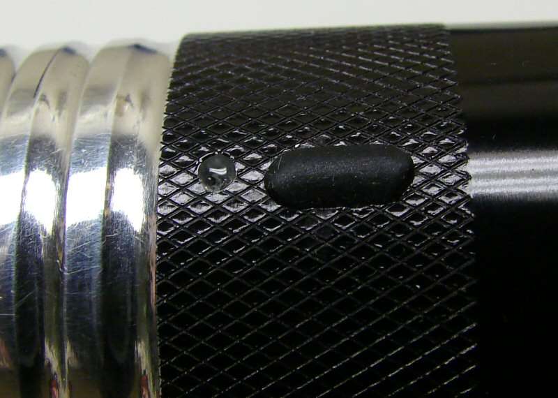
The cap is just a rubber Micro USB dust cap that I have pressed in so it stays in place and seals fairly well. It's not the best, but it does work till I figure something out. The port is on the underside of the light, 180 degrees off the switch.

The socket popped right up in, once I got it aligned in the hole. The spring idea worked nicely.
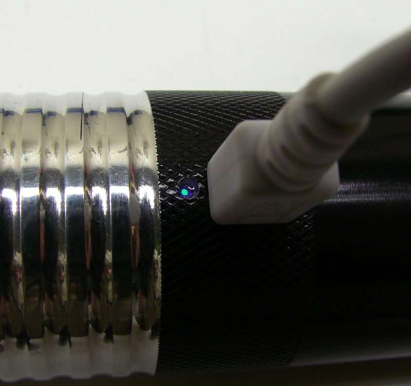
The fiber optic was the best part of this mod. Here it is, with no charge. The hole is filled with epoxy for waterproofing.
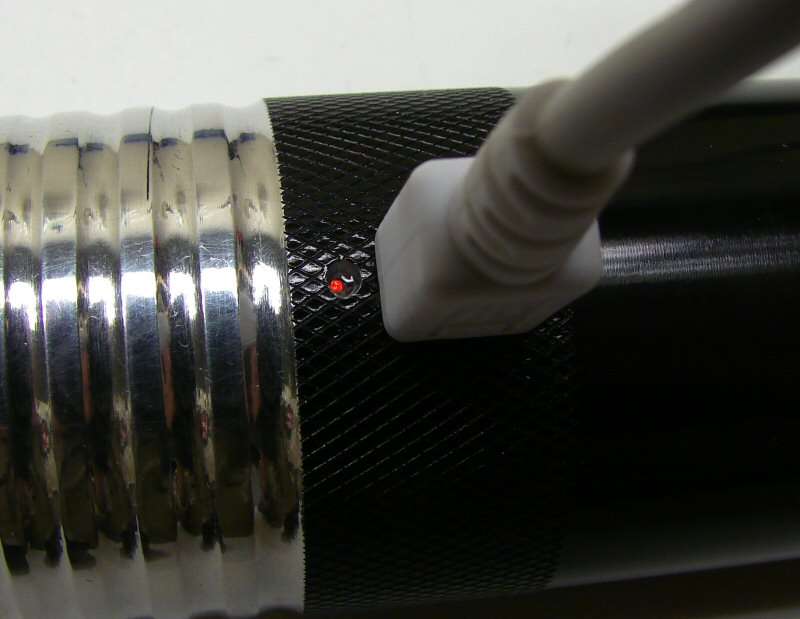
Same optic with a charge. Both leds shine out the single fiber optic.
You will never know just how relieved I am, that the charger mod is over.
That is all till the driver comes in. I am done until then! I am so happy I could..., well never mind.
----------------------------------------------------------------------------
11/29/14
Here's the rest of the story.
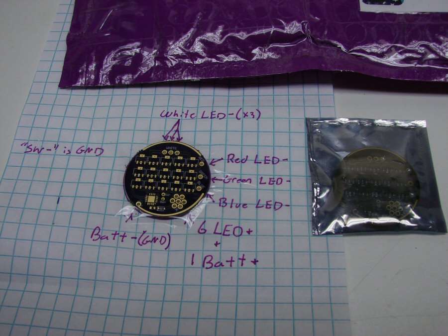
The driver cam in today. C_K sent me a spare and had it all marked out for me. Ha! I guess he took me seriously when I told him I would get lost wiring it up. Good for him.
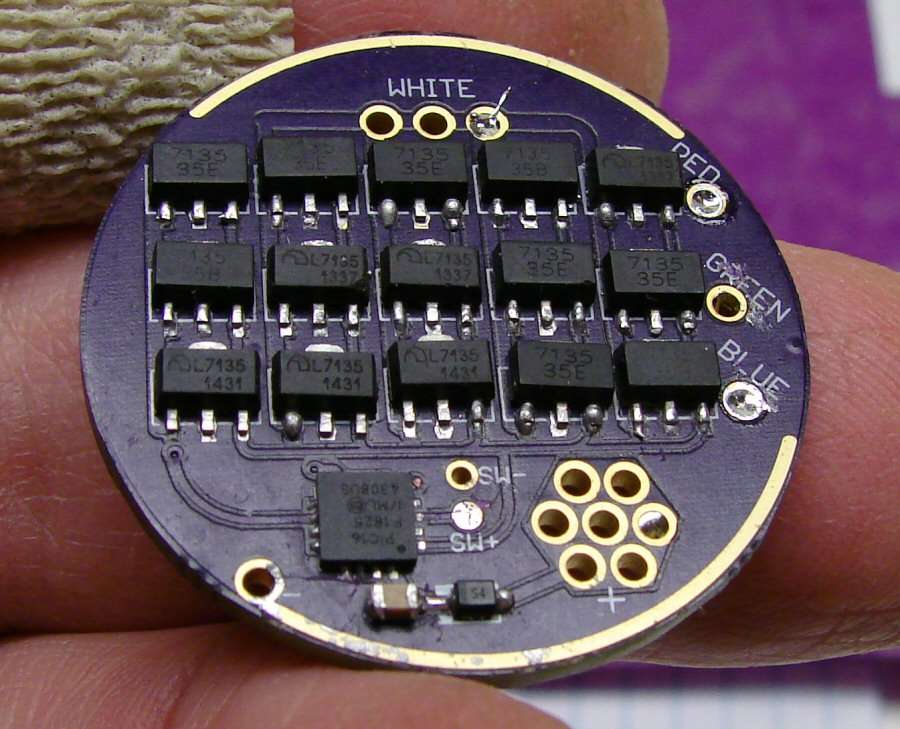
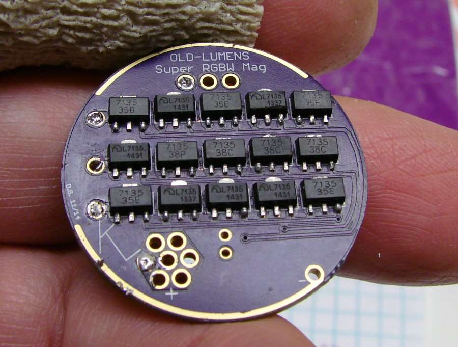
Here's a couple photos of the driver he sent.
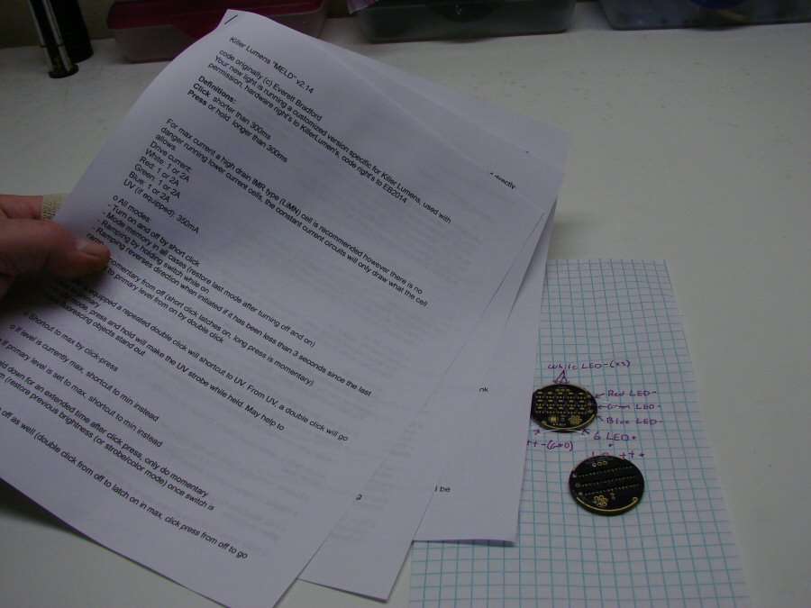
and I printed out the instructions... 5 pages, LOL. Well, I used larger font, since I can't see all that well any more, but it was a waste, since I'm so dyslexic that I can't read it anyhow..

I put 2 vises together, so I could hold everything and get all the wires on. 16 wires all together. Which one was next again?
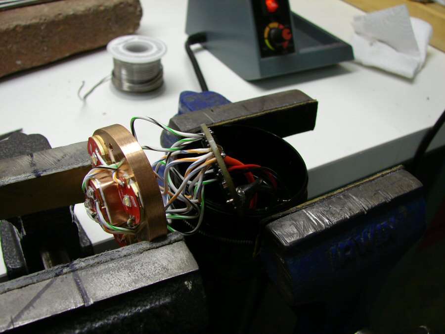
All wired and ready for testing.
Here's a short video to prove it actually worked. I still can't figure out how to makr it run through all the modes. As I say in the video. To me, it's too complicated if it has high and low and off.

The final test - Charging a cell in the light. It charged to 4.12 volts.
Glamour shots
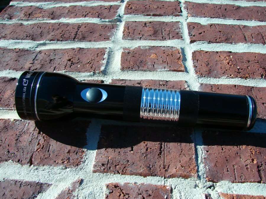
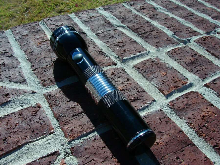
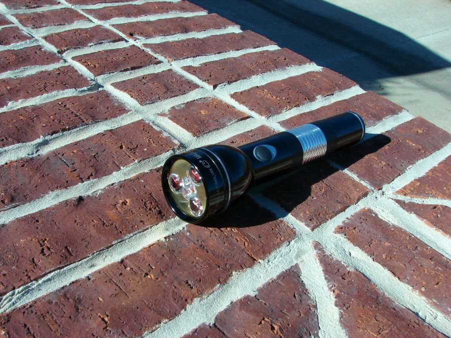
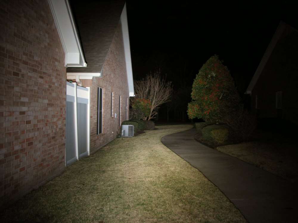
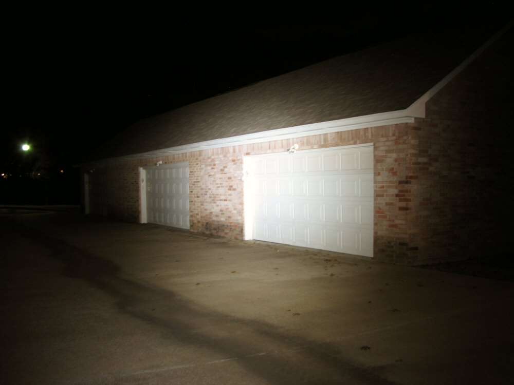
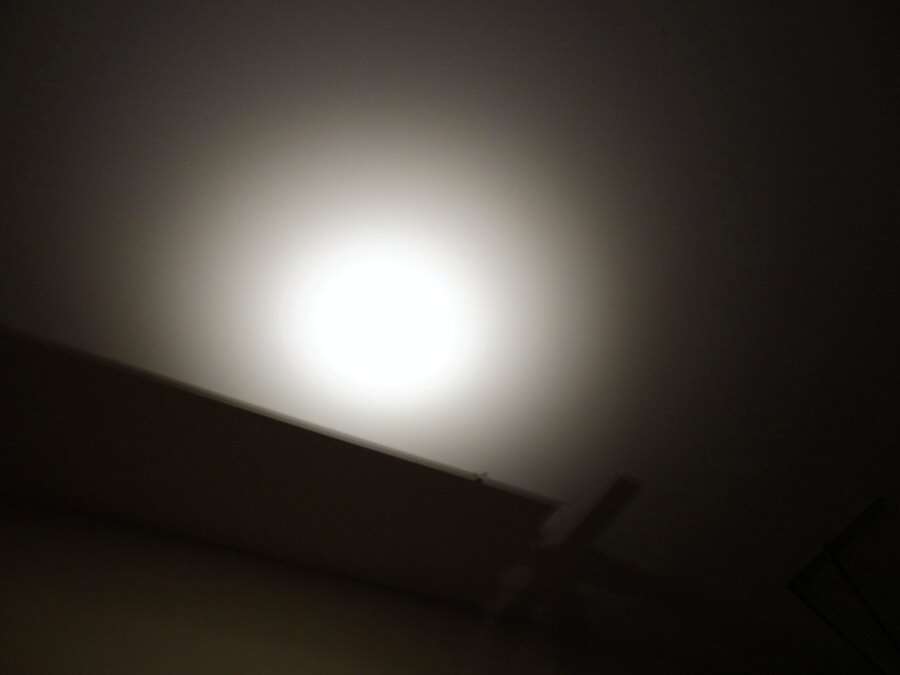
Beam shots tonight, at least with the white leds.
That's it folks.
