@KKW, the reason i am interested in maintaining the CW tint is because if you use a collar, the colder the beam you start out with the more kcd improvement you get, because blue light can excite the phosphors more & you get more recycled light. And i hope to start experimenting with collars in the future.
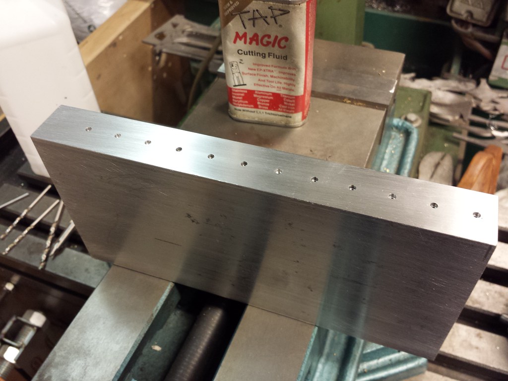
I’ve got a heatsink prepped to burn in emitters. Spaced for 16mm boards on the side in the picture, 20mm on the other. Once I get some short 4-40 screws I’ll be testing it out. 1”x4”x8” aluminum block.
It’s one of a few I have laying around. My biggest piece is a 12”x30”x1” piece of cast jig plate. Mmmmmmmm, flat.
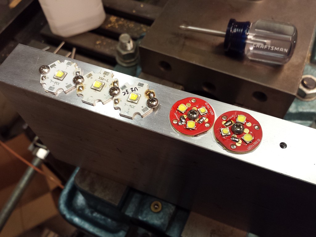
I’m planning on using around 3A per LED, I’ll probably start there for XM-L2, XP-L, and XP-G2. I can run 9 at a time at 3 amps off my power supply with them wired in series. It sounds like 24 hours is the time to shoot for.
I have a recipe that involves graphite, that is if I can successfully expose the bond wires without damaging them
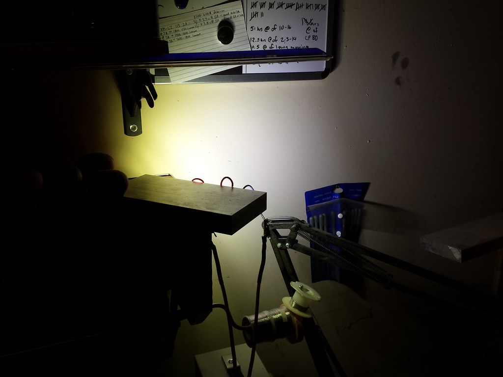
Making light. A lot of it. You can’t tell but it’s in a brightly lit place already, blows the exposure value it’s so bright. Starting off it only pulled 2.55 amps at 30.15 volts, but in 15 minutes that has already gone to 3A at 29.82V. Temperature of the heatsink at the hottest spot on the broad side has stabilized at 106°F. The hottest emitter measurement I could get with my IR temp gun was 250°F on one of the XM-L2’s.
No. They’re gold wires sized to handle rated current with a safety factor that we exploit to push more power than they’re rated for. They act like a fuse when we get overzealous with the current. A non-replaceable fuse unfortunately.
not likely, those wires are way sufficient for the current range that these leds are rated for (hotrod lights use 2.5 times the maximum rated current of the xml2). Btw, the same wires are used from xpe2 to xml2. The xpe2 die dies long before the bond wires go, the xml2 bond wires fry long before the die goes, with the xpg2 it is a close call: the die already turns very blue but still the wires go first.
Keep in mind that there are 64 square inches of surface area to radiate heat just in the two broad sides, and less heat to dissipate than a 100 watt incandescent bulb.
Temperature after an hour is still stable at around 106° at the hottest spot on the broad side.
Edit: And down to 29.25 volts to maintain the 3 amps. I like where this is going. Remember it started at 30.15 volts and 2.55 amps. Even after initial temperature stabilization it was only 2.75A at 30.15 volts.
I started to wonder about the discrepancy between the temperature the of the block I was getting from my ir meter and what it felt like, so I stuck a post-it note to the side and checked the temperature on that (non-reflective) surface. Yeah, that’s more like it.
Interested to see the results here, but I can’t help but wonder what the difference is between running them on the test bench, as opposed to inside a torch?