Attention modders! Please help mod my JM07 Side-clicky

Recently it’s come to my attention my JM07 side-clicky is lacking in wow factor at around 2.3A, so I really want to add some juice as it’s become a bit of a shelf queen, sitting in the shadow of the JM07 pro which I’ve recently modded with a 3.4A Dr Jones Driver. :bigsmile:

Review here:

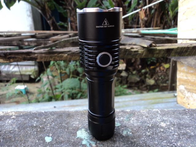
Like the Pro version I figured it would make a terrific host, considering:

  • good heft of aluminium
  • aggressive cooling fins
  • screws to secure the emitter
  • emitter being attached directly to the host with no pill for excellent heat transfer.

My original plan would be to add another 3.4A DR Jones driver. Taking it apart was very easy, thanks to this:

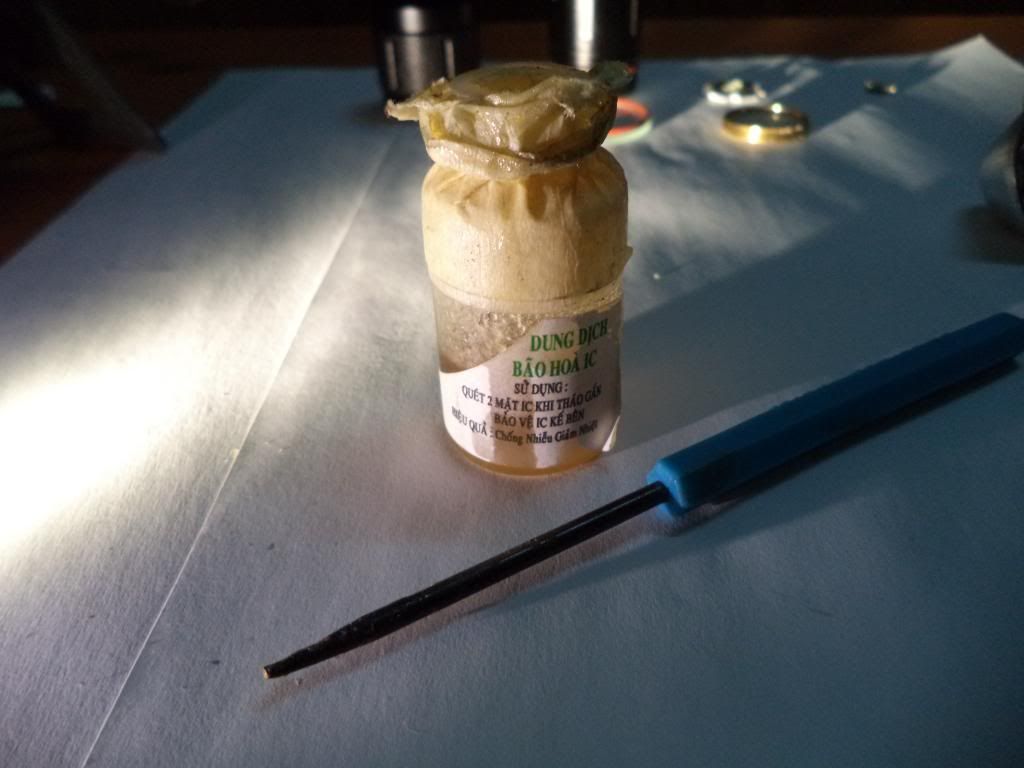
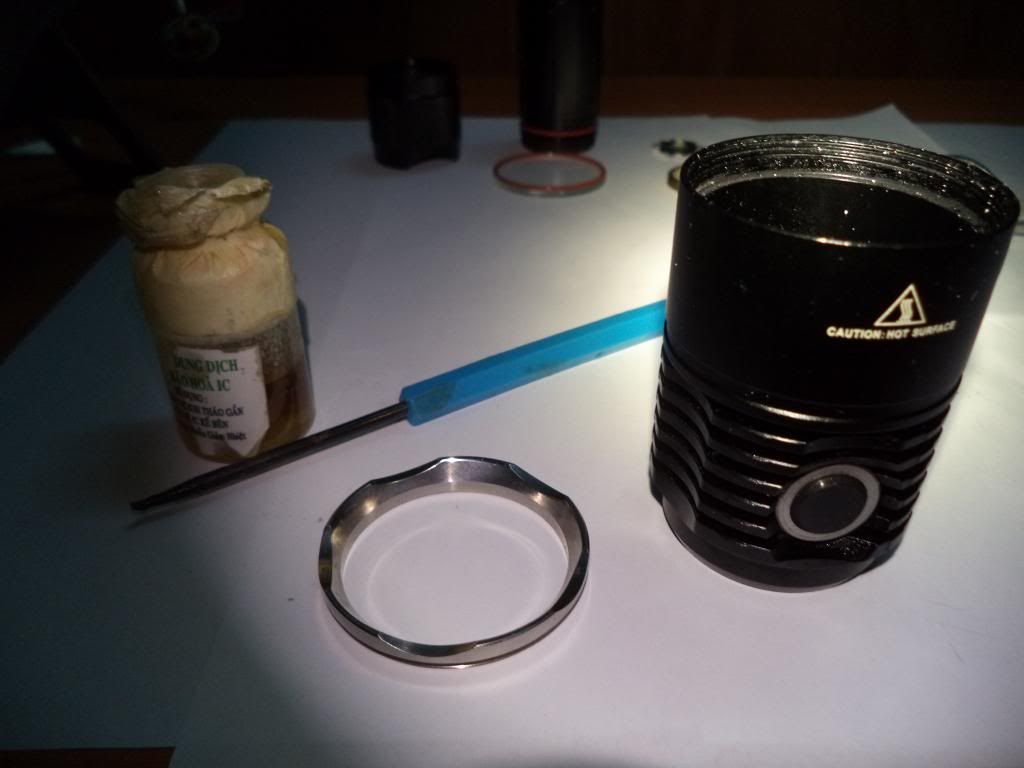
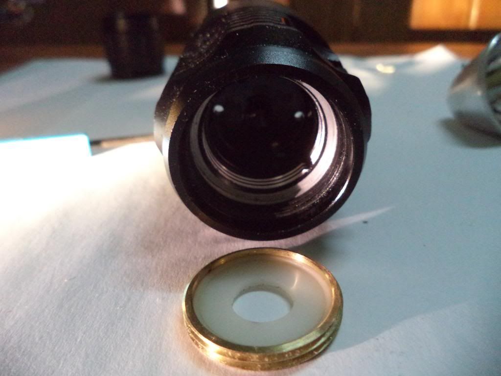
This is a small vial of anti-adhesive that I purchased from an electronic store for around 50c. Both the Bezel and driver retaining ring were threaded and fixed, but almost fell out after carefully applying a thin layer of anti-adhesive to the edge of the threads:

Bezel removed with anti-adhesive

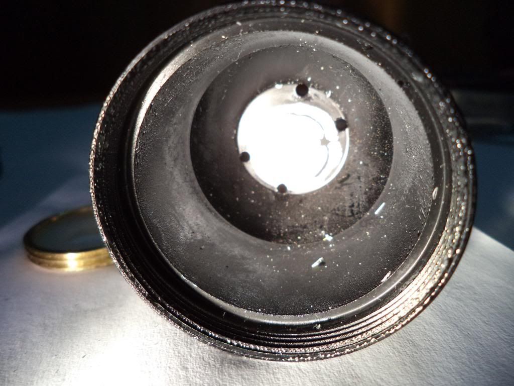
Here’s the driver spring and retaining ring:

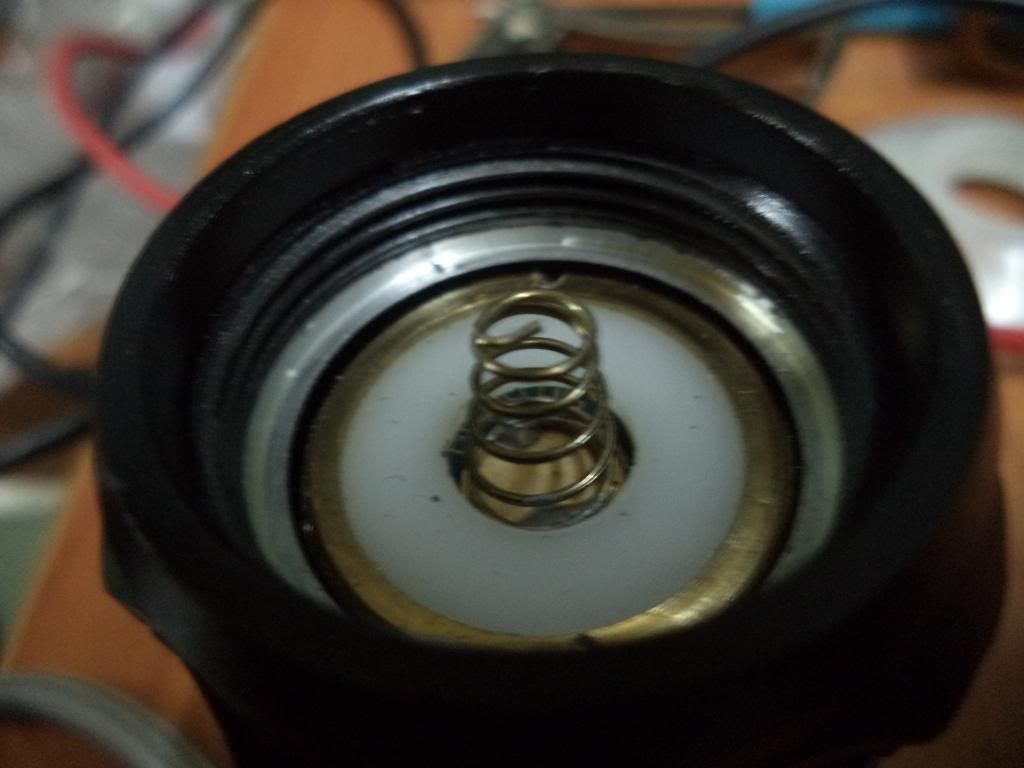
Removed again with anti-adhesive

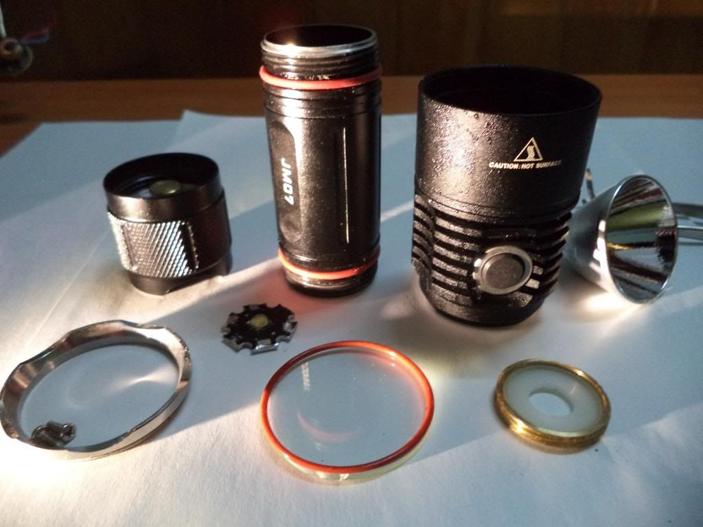
Straight out of the freezer and used a screwdriver to force out the emitter, the only part that required a bit of force and patience:

Fully dis-assembled:

And here’s the driver:

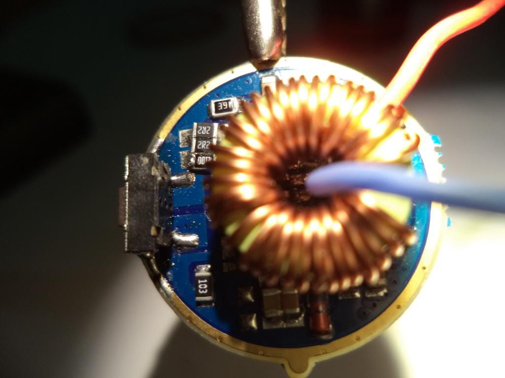
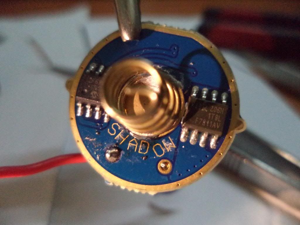
Here’s where I hit a brick wall. The driver diameter is about 22.5mm with no contact board. So I’m hoping to get some advice.

Anyone know of a contact board or suitable driver around 22-23mm in diameter? If I lose the side click functionality it’s not a big problem.

I have a 21mm contact board on the way from int outdoor, however it’s probably too small.

Otherwise, is there a mod I could do to the current driver? Like a resistor mod? I’ve never done one, so could really use some advise here from some of the experts. :~

What about removing all of the components from the stock driver, and using it as a contact board for a Dr. Jones conversion?

Yeah I was thinking of doing that, but reluctant as I could always use the old driver again, in particular the side switch, and I have doubts I can strip the entire board without damaging it. Probably the way I’ll end up going though, although still hoping for another solution. I’ll do some reading up on resistor mods.

Cut a thin strip of aluminum and bend it into a ring. Wrap it around the edges of your 21mm board to increase the diameter to 22 or 23 mm so it will fit the light. Apply a little solder to hold the ring in place.

if so, then DrJones has 3 really neat looking e-switch options, including a new one “mobydrv”. There’s no reason why you can’t keep the switch and have the driver you want :slight_smile:

For a blanking plate, you might be able to find some contact board (like bread board, but with solder holes instead of push holes) that’s about the right size or you can trim some to fit. OL used one to make a battery plate in a recent mod (Sky Ray King?)

I like your suggestion Firelight2 and may give this a go, have you done this before?

Thanks mattthemuppet, I might give this a go. I’m also in contact with DrJones now, great to have him around and love the options his drivers bring.

no problem, he’s a super helpful guy and a real asset to BLF!

Does Dr Jones have a driver which only works from the side-switch and doesn’t need the tail switch?

I know that mobydrv is designed to work purely from an e-switch like the one on the JM07. Check out DrJones’ website to see if it does what you want:
http://drjones.dyndns.info/#over

JR - I’m very new at this so have a few questions:

1) Isn’t the “contact board” the one with the spring in the picture? It seems the driver and contact board are one and the same board but with hardware occupying opposite sides of the same board? Or are they 2 boards back to back and held together by the metal rim?
2) Is the threaded brass ring which was holding down the original 22.5mm board wide enough to hold down a 21mm board also?
3) On Dr Jones’ site, there are pictures of boards on the upper right - are we looking at each side of a single board? If so, then it would seem similar to the single board setup which came out of the JM07?
4) Is there room for another board in the head of the JM07? Since you are going from a single board setup to a 2-board setup?
5) What are Dr. Jones’ board diameters that he sells? Or does he make them the size you want?

thanks.

thanks!

Hi cncyana, I’ll try and answer your questions:

Yes the contact board and driver board are one and the same. There is only one board.

The brass ring won’t hold down a 21mm board, the board will just fall through the cavity area.

Dr Jones’ boards are 17mm in diameter, they can work without an additional contact board, but you need the right setup. They’re too small to work without a contact board on the JM07. Unless he has some other boards or drivers I don’t know about, you should PM him directly.

There is room for another baord, but not a large baord that’s more than at a guess 6mm tall. The cavity area isn’t that large in the new JM07.

JR - thanks for your answers.

1) Did Dr Jones discuss how to solve the too-small diameter board problem (17mm vs 22.5mm)?
2) Dr Jones’ drivers go up to 3A which isn’t all that high. Is there a way to hook up the original board to Dr Jones board to add more power?
3) Are you planning on using Dr Jones’ lumo35drv since that one works for a flashlight with an on-off clicky tail switch and an electronic mode changing switch?

thanks

No probs, haven’t discussed with Dr Jones yet how to solve the too small diameter, I was hoping to get some answers from the forum which I did. I’ll probably use the original driver board as a contact/spring board and remove and desolder all the parts. However one thing I’m not clear on, the mechanical switch is attached to the original driver board, you can see it in the pic. I need to know first if I leave this and desolder the rest of the parts, will it function if I add another board. If so I’ll use Dr Jones’ Lumo35drv.

You might want to PM Dr Jones on question 2 as I’m not sure.

The switch should be an electronic switch and you would need to reuse it. It would need to be hooked to the DrJones driver. He should be able to explain it all to you. I would keep it on the board and just add wires from it to the DrJones driver. You should be able to put the DrJones driver flat on top of the old one, after you remove the components (except the switch).

That is exactly of what I was thinking and hoping to get an answer on, thanks Old-Lumens. :slight_smile:

‘My’ drivers are just NANJG105Cs, but their MCU is reprogrammed with a custom firmware.
These are 17mm in diameter, have components on both sides and are 5mm in height without the contact spring (which is not needed in such a setup).

I modded my SmallSun ZY-T29 just as Old-Lumens described (I additionally removed the NANJG’s spring).

Hi Dr Jones-

1) The pictures of your boards look like they have a spring in the middle- is it just a metal button for the positive battery contact?

2) If the wires from the e-switch are connected to the contact board, won’t the full current from the battery go through those wires to the e-switch?

3) Your boards max out at 3A. Can we increase the amps to 5-6amps by stacking boards?

4) Your lumo35drv default low mode is 25% power. How do make it lower to 1%? thanks.

1) Just a battery contact spring, yes.

2) No, the switch is not in the mwin current’s path, its just connected to a pin of the MCU.

3) Yes, a maste-slave setup is possible.

4) I can adapt that before shipping the driver. lumo35drv is not ‘programmable’.