(thanks, I think it was TK? who gave us the wise comment in that light’s thread about putting pressure on the lens while turning the bezel, to keep the spacer from lifting and rotating with the reflector as it’s turning).
I opened that light to get the O-ring back where it belonged, not just for the fun of taking it apart.
Though taking them apart is much of why I’m here and not in the other place.
Usually I feel lucky. And when I’m not lucky, I learn something useful for next time.
This is next time, for this particular issue. We learned a way to do it wrong, from the last time.
Everyone please forgive me for this suggestion (I definitely don’t want to offend any X6 team members either) but can the SS version be bored out in the battery tube midsection to decrease unnecessary thickness and weight (total weight is 14oz with battery)? I love the look of the SS version way more than the much-lighter black Aluminum version but the SS/Cu version weighs about x3 as much (which is what we expected for an SS host anyway). Some will no doubt pick up the light for the first time and think, whoa, this thing is a lethal hand weapon but not an EDC (last night I picked up a 15oz tall skinny jar of jam and figured out this weight isn’t an EDC - just something to think about). Or is there someone here capable of performing this custom work on a completed tube?
Agree, i am sure a eagle able designer could make a beefed up switch pcb with lots of wide copper traces & vias so we don’t even need to bypass the switch pcb for the very real fear of burning out the traces.
Slap a copper beryllium spring on that or a carobronze if copper isn’t available & we would have a from the manufacturer ready made switch bypass, but something that could actually be produced just like they assemble the part now, just upgraded like we have done to the driver.
The switch pcb & spring upgrade could be the next step up in BLF edition performance
Just as a side note, the copper beryllium springs in the Noctigon M43 tend to flatten out and lose contact with the battery due to lower tensile strength of beryllium copper. Maybe we can make the tailcap compatible with a standard forward-click McClicky which is capable of over 5A if I remember correctly.
Here is a quote on CPF about the McClicky from the guys at Oveready:
“Most switches route power through the same spring that pushes back against the button. The McClicky spring pushes a solid bar, that itself conducts the current (think draw bridge). This provides greater amperage and less resistance than switches several times larger.”
That might have been me. I discovered that trick on my third attempt to re-seat the O-ring on my BLF A6. I wrote it up for the A6 troubleshooting thread.
Copper-beryllium comes in various alloys, the one that intl-outdoor chose has a very high conductivity but that goes at the cost of mechanical properties. A beryllium-copper spring that does have proper mechanical properties for a spring has about the same conductivity as a (cheaper) copper-bronze spring (=about 3 times as conductive as the common steel spring)
Nice story from Oveready: the build design of the mc-clicky with the current not going through the internal spring of the switch is the same as the dirt cheap Omtens and brandless clones, which indeed perform really well at high currents. Only really small lights come (rightly so) with switches that carry the current through the internal spring (they fry with too much current)
there is a difference between every day carry and every day use. you maybe right that this light is built to be used every day but set down when not in use, think (tool box, desk, drawer, etc ,etc).
how much weight could be saved?
some, alot of us are going to go and throw a big heavy copper heatsink/spacer and make this a triple or quad emitter light. So many of them will end up at over a pound, but oh what a glorious pound it will be
I think you have a very valid point about the weight and “EDC”. I have to say the availibility of both Black Alu finished units and raw Alu hosts really are good answers to your concerns.
After reading the weight information. I decided to keep only 1 of the SS/Cu set no 177. Please remove me from 178, and add me back to the aluminum 1 set - CW.
If they haven’t completely redesigned the tail cap then it’s probably going to have a mini omten in it. I might braze up a copper button cover for this one.
It isn’t the switch itself that is the week link here, the omtens work great.
But the spring + the spring pcb’s traces that will burn out if you push to much amp though them, that is why we bypass them with wire to protect them from failing prematurely.
And because that is the only week link left in these BLF edition stock hotrodded lights, i hope that can be sorted in some way.
I am sorry i haven’t followed your lighted tailcap PCB thread recently. Do you mean you already have a beefed up enough switch pcb that doesn’t need pcb bypassing anymore in triple & quad lights?
To be honest one of these “eagle able designer” i had i mind was you of course
EDIT
YES i just checked you are right that is much beefier maybe it was from your lighted tailcap pcb i got the idea……? How strange i though it was something that needed to be created, i missed that your switch pcb already had that feature.
Nice do you think it would be even less resistance if you filled the rest of space on the trace with vias, like Richard does on hit MTN board’s positive pad? But i am no EE and don’t even really fully understand the construction of the pcb’s though.
This is great that means the pcb already exist if the organizer for this or future GB’s would want to use it, if that is ok with you of course
That means this switch pcb + some sourced lower resistance springs and this could be solved, that would also mean a future Manker triple should be more possible especially if a temp controlled future driver could be used.
And who knows maybe even with a lighted tailcap in a future GB I would like to see it, but it would complicate thing with more components to source though.
Its all about samples and how they perform at this point. Once we get them tweaked to where we want them, we will know more about when this GB will happen.
It’s funny you mention that… There was just enough time for a last-minute upgrade before the samples ship.
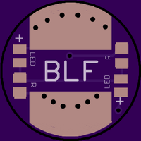
Not only thicker traces for higher current, but when the front of the light is off, the back turns on. It’s an ingenious design pilotdog68 came up with — if I understand correctly, it reverses the flow of current depending on the state of the switch. One direction drives the main light at full power, the other direction lets only a tiny trickle of current through to drive a low-power tailcap LED.
Try to ignore the pink boot; sourcing clear ones takes a while and this was done very quickly so they used the closest they had laying around. It seems Manker was too excited about the idea to wait.
Achievement unlocked — lighted tailcap!
(pending review, of course, to make sure everything still works correctly)
The next step is thorough review of the samples when they arrive, and then if everything checks out we can give a green light for production. Or if there are issues, go through another round of refinements. At the very least, I’ll probably need to tweak the calibration and send new firmware… I hope that’s the only change needed, since it’s easy and doesn’t incur shipping delays or production costs.