I’ve been using the LD-2 driver in the triple pill and the retaining ring that came with the TI, and I’m finding the problem I mentioned in that other thread. Basically, it seems like if I use a longer battery like my Eagletac protected, the light turns on in high mode when I start screwing it together. I’ve covered the battery side of the LD-2 driver with kapton tape now, so it can’t be shorting there, so where else? I suspecting that maybe the switch side spring may, which is kind of long and soft, may be “leaning over” and touching the body with the longer battery, but obviously, I can’t see inside the light.
I also have a spring on the LD-2, but it’s pretty small, so I don’t know if that could lean over (but maybe)?
Did anyone have any problems with this? Any other ideas?
Thanks,
Jim
EDIT: Also, how does the “stock” switch cap come apart? I’ve tried unscrewing the nylon piece at the front, but it doesn’t budge. I was hoping I could switch in a shorter, stiffer spring.
The switch doesn’t readily come apart which is one reason Wefans offered a new one. Cells don’t seem to go into the tail past the female switch threads so a tube or sleeve around the spring that covers those threads might solve the shorting problem. It may be why some lights use a cap and sleeve approach on their battery connections.
I was just about to post that I think I’ve found the problem. It looks like there are some tiny spots on the tail end (on the sides) where the insulation got broken through, so those were shorting the negative side.
What started me looking at that was I was doing a test with the light body assembled, but without the tailcap at all (i.e., the tailcap end was empty, and as I was screwing the end tube in, the light came on… and I went “Huh?!”.
Looking into the tube more closely, I think that what is happening is if the battery negative end goes further back into the tube where it is past where the threads start, that is cutting the battery insulation.
I don’t know how it is for others, but the battery tube on my BLF TI is SUPER tight. I cannot even get some batteries to even go into either end of the tube!!!
Can you explain about the sleeve thing you mentioned? Since the battery tube is already so tight, I think that if there was any sleeve in there, that would not allow any batteries to be pushed far enough back to contact the switch spring?
For now, I’ve put some tape around the Eagletac near the negative end which makes it a tight fit (the Eagletac is “slim”), but it seems to work.
I’m not sure what a good solution is for this, other than only using slim batteries and never force a tight fitting one?
I machined a few thou from this area for the battery to install crorectly. I'd suggest if you had a Dremel and flap wheel you could do the same thing quickly.
One of my Reylights uses the LD-2 driver with retaining ring and without problems.
There are traces on the battery side of the LD-2.
I put a tiny ring of solder on the rim of the battery side of the driver to make sure the traces are not shorted by the retainer when the retainer is snugged down.
Spring on driver not needed. Takes room. Use dab of solder or one of RMM’s little brass buttons instead.
Test the completed driver/emitter/pill/ installed in the head with a battery and a couple inches of wire for the ground. Make and break the wire to sequence the light through its modes. (careful! not to short the battery!) This may help determine which end of the light is causing problems. A too tight battery can torque things out of alignment at either end of the light.
There’s already too much spring on the switch end; don’t want to add more on the driver end.
Thanks. I’ll try adding some small solder blobs to the battery side ground ring. That’s probably a good idea regardless.
As to which end is causing the shorting, as I mentioned in the previous post, I’m pretty sure that it’s the shorting to the battery case near the tailcap end.
I’ll think about removing the spring from the LD-2. The thing is if I do that, then the light won’t work with flat top batteries, I think?
BTW, which batteries do you use?
Thanks for the hints/tips. Back to the basement for me :)…
The sleeve would need to be slightly shorter than the compressed spring. It’s just there to prevent the spring from flexing sideways into the side of the host and bypassing the switch.
One way to remove some extra thread material would be to mark where the switch needs to bottom out and install the switch retainer only(no switch)to that point and use it as a stop for any Dremel work. My preferred method is to wrap some masking tape around a 5/8” drill bit with ~ 3/4” wide x 2 1/2” long strip of sandpaper (w/d200) secured under the last 1/2” of tape. Adjust how snug it is by adding removing layers of tape. Back up the retainer with some tape on the button side to keep it from spinning out while you drill. You should be able to spin it down to smooth metal. This might seem at first like a hack method but I assure you it can be extremely accurate.
I added the blobs on the ground ring and removed the spring, and I deposited a rather large blob of solder on the spring pad. It kind of works, but now it looks like it won’t work with flat tops.
I find that Efest purple 18350 cells work well in this light, but I’m using it in shorty form. Earlier I also found that a 20R / 25R cell worked, but only if it was bare and not the button-top version.
I used a brass button on the driver since I saw no point in putting a spring there.
I didn’t realize that the 20R was available in flat top. I’ll see if I can get those, because the button top ones are really thick (I’ve had problems with it in other lights also).
A cylinder hone would work abeit more slowly. One advantsge to tape and sandpaper is you can target the removal to just where you need it with the width of sandpaper used.
To followup on one part of this discussion: So others (you) have also had problems with the BLF TI with tearing the insulation at the end batteries and it is because of the threads being exposed and so deep into the tail end of the battery tube?
Also, about the hone (and also the sandpaper approach): Since the material is TI is that a problem? I thought that TI might be too hard t sand/grind?
As I said, I’d also like to bore out the whole tube “just a little” because it is so tight now. Is that advisable (or not), probably using a cylinder hone (I’ve wanted to try one of those for awhile)?
I found a small brass (I think) kind of (short) top-hat shaped piece in my junk box. I don’t remember where I got it but I think it was used to cover the driver-side spring from one of my lights that I modded. It’s thick-walled and short, so it’s not like the tailcap spring covers.
Anyway, I sanded the “top” end, fluxed it, and pre-tinned it with solder and then soldered it with the “top” end soldered to the positive pad on the LD-2. I then filled in the open “bottom” end so that there was a slight bulge, so that it would work with both button and flat tops.
That seems to work now, so I now can’t screw the body totally together with longer batteries like my Eagletac protected (I can still adjust the tailcap on the BLF TI to compensate I guess, giving up tailstanding).
So, it looks like the remaining problem is the body inner diameter. I’m going to get one of those honing tools and try that, but still am wondering if those’ll work with TI?
Ti is harder than aluminum but not impervious so either one should work to smooth the extra threaded area. My concern with the hone is the one I’ve seen have pivoting segments that might sit unevenly if only partway on the threads. I’m using power pack pulls so the width issue is only relevant for me at the excess switch threading but I’m not doing anything to mine until I get the new switch hardware.
Actually, I’m willing to try your tape and sandpaper approach, but could that also be used to bore out the tube a little bit?
Also, I’m having a hard time coming up with a “mental picture” of what you’re doing? Do you wrap like a TON of masking tape around the drill bit to make it thick enough so it’s about 18mm diameter and then wrap the sandpape around that big hunk of masking tape?
Exactly. If you start with a drill bit that’s maybe 1/8” in dia less than the tube size then you don’t need as much tape. A section of dowel works well also and doesn’t have the flutes of a drill bit so sanding is more continuous. It needs to be a snug fit in the tube to get good results otherwise you won’t have pressure to do the sanding. I use the technique to sleeve micro mags and also to get fins just the right size. Here I used it to go from a 3/4” hole saw out to the OD of 3/4” copper pipe. Be sure to wear gloves because the metal gets hot and if it slips it will raise blisters. A tape wrap on the tube will serve to protect it and give better grip. To ream the tube a bit I would suggest removing the unneeded threading first and then enlarging the bore so it’s less likely to have a taper.
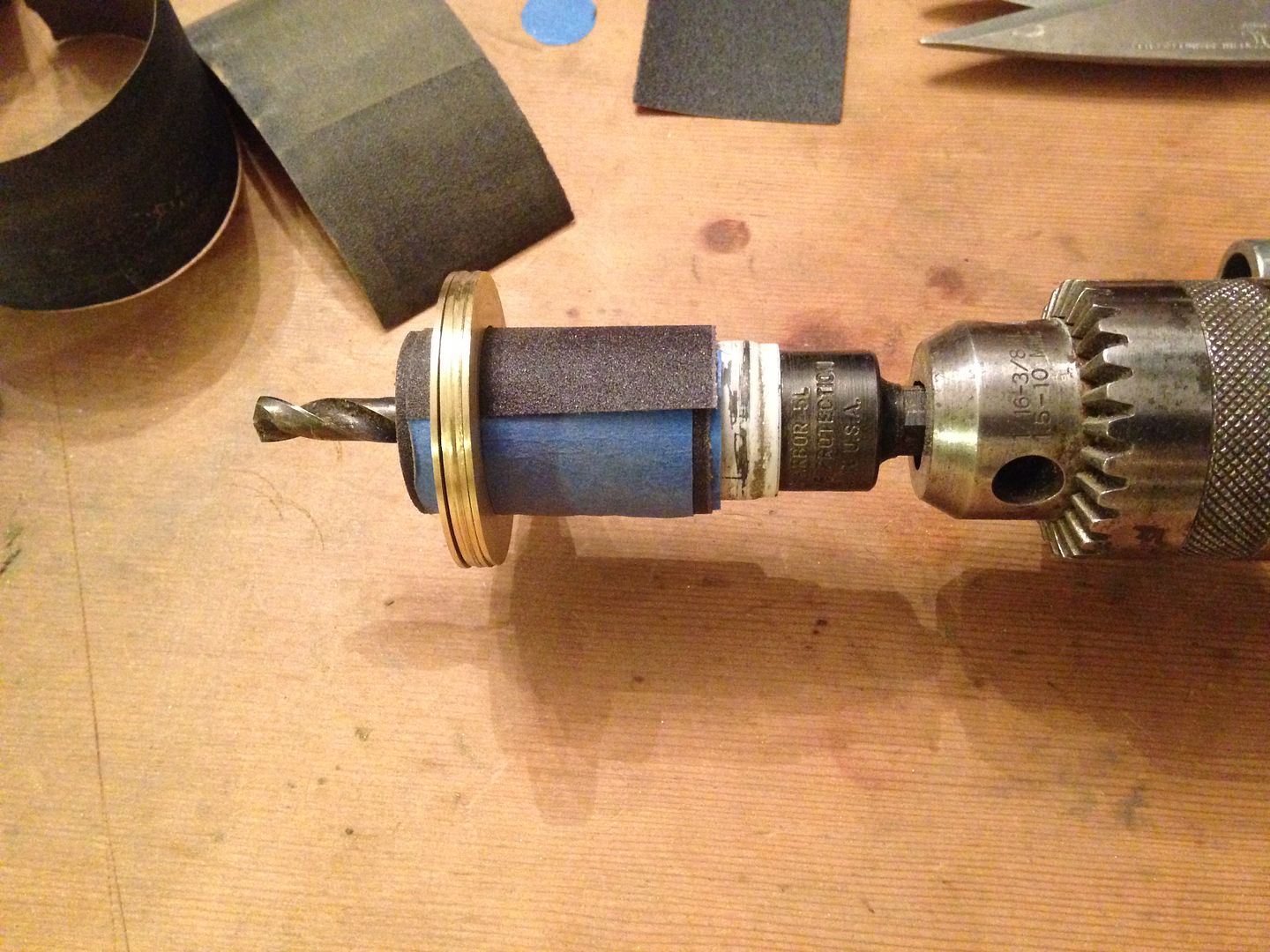
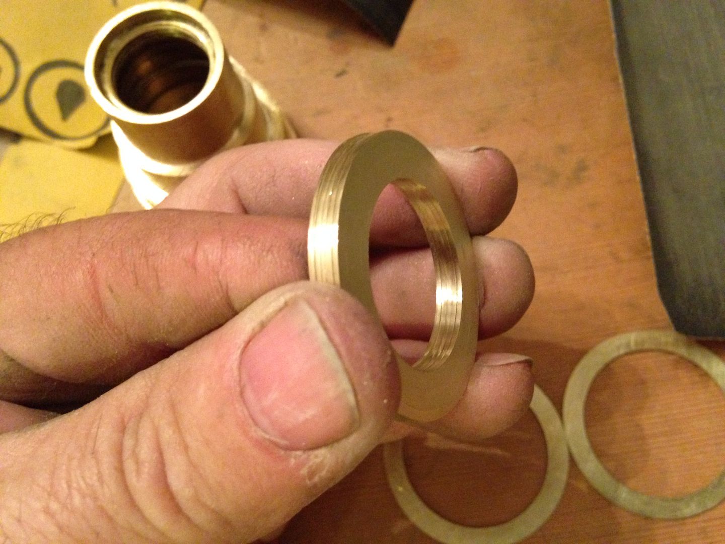 Here I used it to go from a 3/4” hole saw out to the OD of 3/4” copper pipe.
 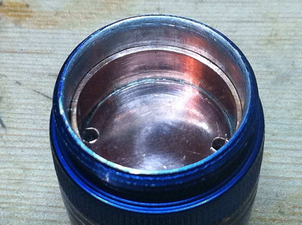 Be sure to wear gloves because the metal gets hot and if it slips it will raise blisters. A tape wrap on the tube will serve to protect it and give better grip. To ream the tube a bit I would suggest removing the unneeded threading first and then enlarging the bore so it’s less likely to have a taper.