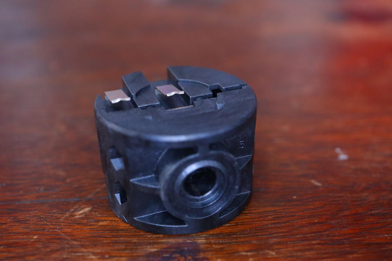
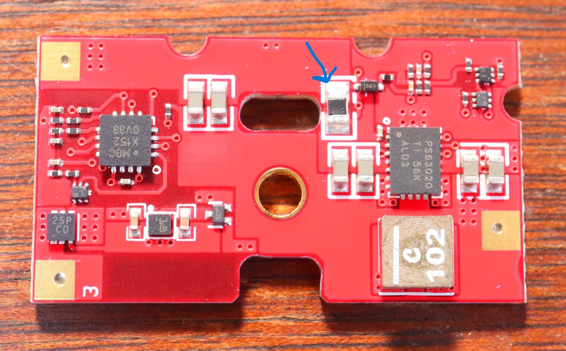
Hi all, This is the driver from my Maglite ML300LX 2D. I suspect its a boost/buck because I can run this light on a 3.7v Li-ion just fine, and it does not effect the output.
Does anyone see components on here I could potentially swap out to get an increase in drive current?
Thanks for responding. I’m getting about 550 ma to the LED.(EDIT: That cant be right, something must be wrong with my DMM, I will try again and get back to you)
Do you have a guess as to what I might add to it or swap it out for?
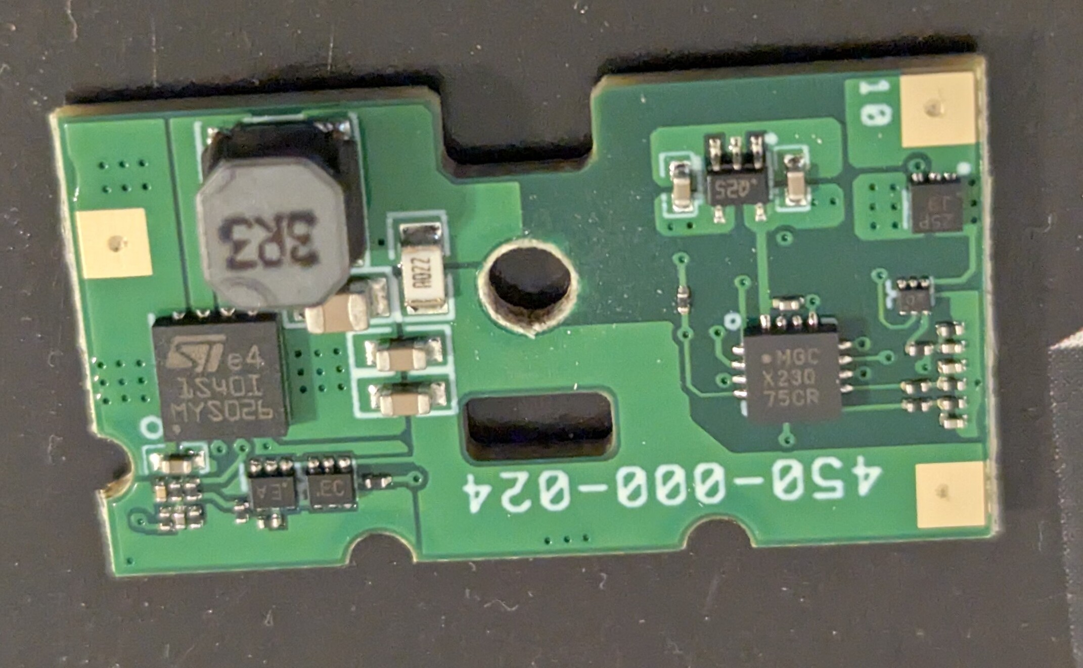
I’ve never had another one of these apart, but I am guessing the driver in all their lights is the same or similar. I see the ML300L 4D has an output of 1000 lumens which is double what the ML200LX has. So hopefully this driver can handle double the current. 1.0-1.5 amp or so?
This also has me very curious as to what the maximum input voltage for the driver might be.
I must have had a loose connection, or a glitch with my clamp meter. I measured again and this time I got 1.4 amp.
If I am not mistaken the ML300LX is using a Cree XML3. So that would be more in line with the rated output of 487 lumens (which I have confirmed is an accurate rating)
Anyway, because there are no marking on the sense resistor. The process would be to measure the output current and measure the voltage (Vsense) across the sense resistor, preferably at the same time with another DMM. if not at the same time then measure med and low modes too and check that the calculations match with high measurements.
It’s just ohm’s law
Rsense=Vsense/Iled
Then for the the sense resistor for the new current :
newRsense = Vsense/newIled
No, with li-ion you can up it to 3A.
Edit : also dont measure at low input voltage, say 3V min, to be sure the BB IC isnt throttling the output below the target regulated current due to input overcurrent.
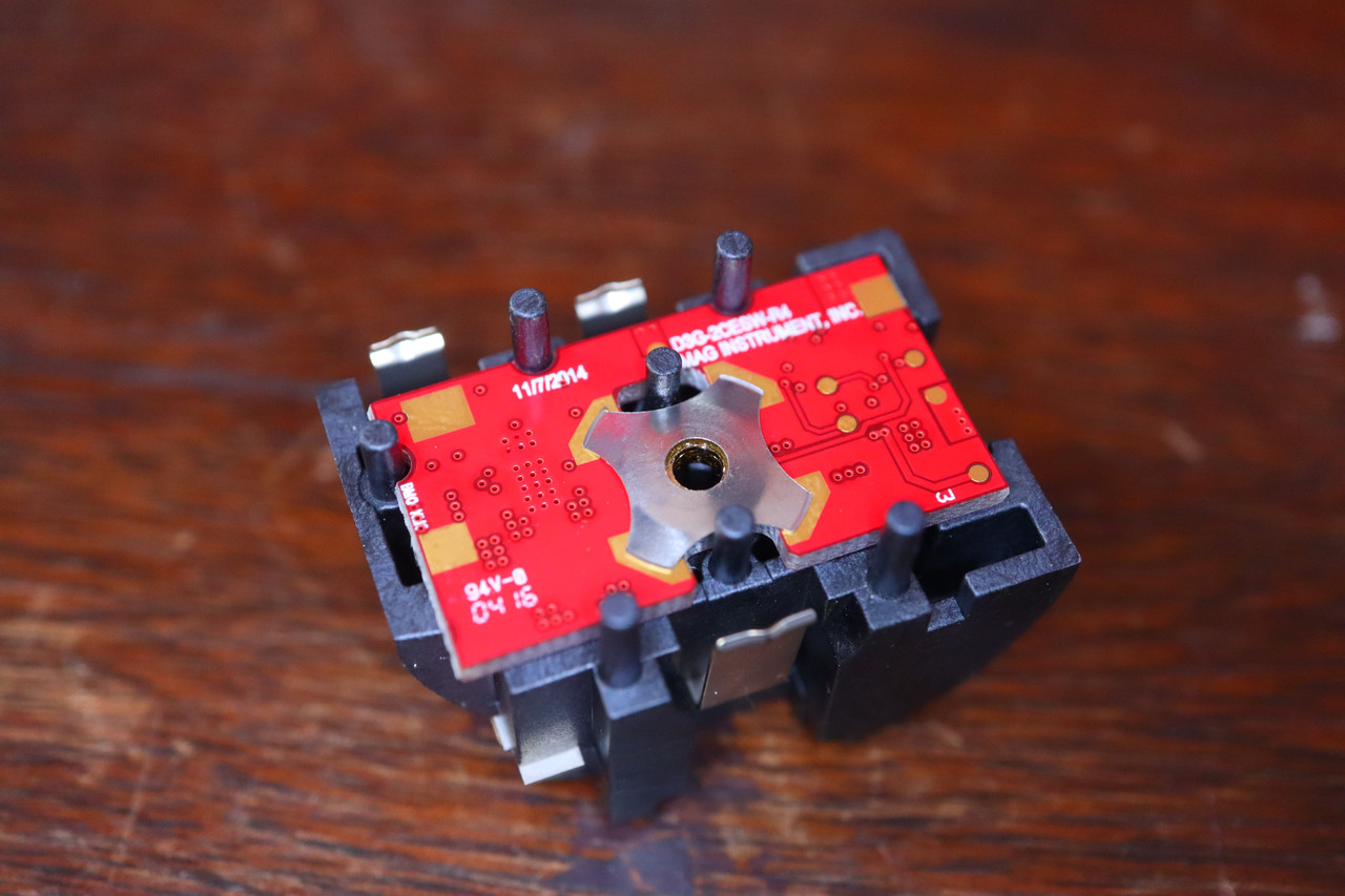
Thank you for the input. I was not able to get a measurement across the resistor, because to test the driver outside of the switch takes 6 connection points, including the two for the switch which is on the opposite side of the board as the resistor I need to test.
I have a multitude of of various resistors in a wide range of values. I am thinking about just soldering another resistor over the top of the factory one, to see if I get an incremental gain.
If you had to guess, what value do you think would be safe to start out at? I don’t care if it takes several tries for me to get it right, I just don’t have even a ball park idea of what value to start at.
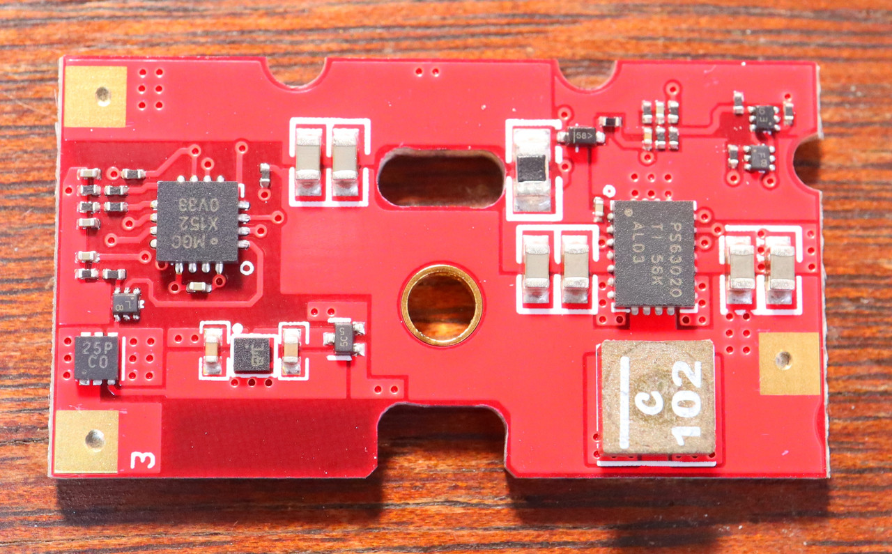
Don’t know the exact MPN of the LDO (likely the SOT-23-5 top right), but 4S is like 6.4V of alkaline, more if lithium primaries, LDO usually come in 5.5V, or quite a bit higher, like 12, 15V or more, so it’ll probably be fine.
Going back to my original post for a moment. I soldered a bunch of wires to the driver from my ML300LX 2D so that I could attempt to measure the value of the current sense resistor.
I tried two methods. For method one, I hooked a clamp meter around the negative wire going to the LED, and then used the leads of my standard DMM to measure voltage across the sense resistor. I powered the circuit on, and waited for the current to reach peak before taking my measurements.
Method 1 results:
Current to LED in high mode 1.44a Millivolts across sense resistor 32.1
Current to LED in Medium mode 0.24a Millivolts across sense resistor 5.3
For method two I used a second DMM and just let the current to the LED run through the DMM.
Method 2 results:
Current to LED in high mode 1.52a Millivolts across sense resistor 32.8 Current to LED in medium mode 0.26a Millivolts across sense resistor 5.4
So if I take the numbers from method 2 on high mode the calculation would be this?
0.0328 volts / 1.52 amps= 0.02157 Or roughly 21 milliohms. Right?
So if I want to basically double the amount of current I am getting get say around 2.9A peak I would just double the value of the sense resistor? Add another 21-24 milliohm resistor on top of the original in parallel (ie cutting the resistance in half)?
That is the TPS63020 product page you linked to. Forget about that little picture when it comes to what the markings on the chip are, those pictures are always just renderings with generic logotypes. The usefulness of that picture is the pin count and pin layout, and it’s spot on.
The 4A limit is switching limit, not output limit. You won’t be able to get a reliable output of 4A out of it. I can’t say I’m very good at this stuff so I am open to being corrected, but I wouldn’t be aiming for anymore than 3A out of a 1S buck boost chip that has a switching limit at 4A, and that’s only if it doesn’t boost the voltage that much (LED with low VF).
That photo you provided, the current sense resistor (the one you put a blue arrow on) looks like it can be replaced fairly easy. If you can’t measure it’s value, I would start by replacing it rather than adding resistance to it. I would start with a high value resistance like 10 ohm and measure the output. Then you should be able to make a calculation of what the value of that resistor should be to get your desired output.
For a noob designer like myself, the interesting part is that component just to the right of the current sense resistor. It certainly looks like a diode (Schottky or Zener). I’ve not seen a diode used like this in any schematics I have seen before. I wonder why it’s there. Anyone have a good answer?
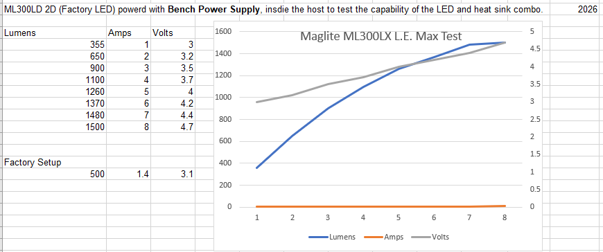
In my tests the heatsink seems adequate. Maglites own 4D model is rated at 1000 lumens.
I did a bench test where I raised the current slowly to see where the point of “no returns” was. IE the place where adding more current stopped getting more lumens and started giving me less.
At 4 amps the output is pretty stable, it can sustain around 1100 or so lumens. Adding more current than that not only diminished gains, but at high current the output would eventually fall even further.
I pushed it all the way up to 8 amps briefly.
To be clear all of that data is with the heatsink relatively saturated. If I were to cold start the light at 5-6 amps the output would be substantially more (probly 1800+).
Only time will tell, but I don’t expect the LED to suffer any damage as a result of this mod. If anything I would consider the driver more of a weak point as there is no heat sinking for it.