Code now public! BLF A6 FET+7135 Light. Short 18350 tubes and Unanodized Lights Available

Excellent.

I am excited for your firmware. I have built a number of those drivers, but was using the original STAR_offtime with it’s limitations.

I think I have about 15 or so of those waiting to be assembled :bigsmile:

@Dale, 1659.45 lumens that is a lot :bigsmile: interesting that with the new firmware that don’t engage the 7135 at max, it now pulls less Amp but more lumens, i guess that means the 7135 just really held things back before just like TK explained.

The whole circuit looks to be so efficient now, that even slightly lower resistance ups the output a lot, maybe you could test an upgrade to 18ga wires from the driver if it fits? I think i remember you using 22ga silicone wires now, that is the last & only thing i could possible think of that could up the output even the slightest bit more :wink: and if a 18 gauge wire don’t up the output, then at least we would know that a 22 gauge is good enough.

I just got a bunch of nice wires in various gauges from RMM today, so i will try to learn what trade offs there is with regard to wires sizes and what is really needed at different expected Amps before i get noticeable losses.

@Dale & TK, what is the R1 resistor value you are using now? i will probably order some FET+7135 boards from ospark as soon as wight’s latest soldereable star improvement is ready :slight_smile: and i just want to make sure i got the needed resistor values for the values calibrated in your firmware.

@TK, i like that 4 & 7 mode possibility, i know people requested a 4 mode driver & the cube-root model for visually linear output between modes is a very nice improvement also, i wish i could understand it mathematically but my mind just can’t process too advanced math successfully, i just get a headache when i try :frowning: but i am glad others like you can and we all get to benefit from it :slight_smile:

Forget about it :) TK's kindness being willing and wanting to help has added a whole new dimension to what we (at least "I") thought would be possible here. At best I grab a bit here and there (no pun intended) :)

I do not know when Wight will finish or publish the driver with the star. He has been extremely busy. We currently are using without the star and if you already have the other components I would just go with it. If you haven't used this driver yet (even without the 7135) you are in for one hell of a treat. :)

I have said this before and I will keep saying it.... For those that do not build their own drivers the 17DD from RMM is what started this whole thing. I built an S2 Triple with that to start and just built a couple more with that 17DD. If anybody is holding out just for Wight's driver they are actually depriving themselves. It is well worth the money! :) and.....it CAN be used with 2 cells with a Zener mod.

  1. Richnpc NW

Please put me down a CW also.

Correction for Clarity on Bugsy’s 2 cell statement…

It can be used with 2 cells with the proper changes, the Zener addition and a swap of a 200 ohm resistor in place of the diode. What this does is allow the use of 6V emitters. This DOES NOT enable 2 cell use with a single XM-L2, XP-L, XP-G emitter. The purpose for the Zener is to protect the MCU from 8.4V from the 2 cells. You’ll still be feeding 8.4V into the emitter and will fry a single 3V emitter. This mod works for the XHP series as well as the MT-G2 and any other set-up that requires 6-8V. It won’t power 9V, ie: triple standard emitters.

You could, however, use a 2S2P set up and power a Quad with the Zener mod. (works beautifully) To clarify, 4 XP-G2 or 4 XM-L2 or 4 XP-L emitters, wired 2 pairs in parallel, run very well on 2 Li-ion cells. I built a Quad XP-L for an Solarforce L2X this way and it’s very cool. (the legendary meat tenderizer light). This is the way the Quad mcpcb is set up to be used, making it super easy to wire with a lead on each side of the board and no 3rd wires or jumpers.

We now return you to the regular scheduled program already in progress…

@bugsy36
I got an BLF X6 with the BLF17DD driver & and plan to build a triple with one, all i need is the host that is in the mail, so yeah i get you a good FET driver is an improvement to almost any light, if it is more output you are after :wink:

I am in no rush i can wait, i spoke to wight by PM’s and he offered to send me the needed gerber to order it from ospark, but that may have been an older version, because TK indicated a recent change of the star to the battery side, and that is something i have been wanting since wight started this whole A17DD-SO8 journey that eventually resulted in the FET+7135 driver, if feel the configurable star plus TK’s firmware for the 2 PWM’s driver really makes it usable for most uses even without tuning the firmware for different mode setups.

Cajampa, the proper set up is a 223 at R1 and the standard 4702? at R2 (memory strikes again) We used to use an 1912 (19,100) at R1 as it was what was on a standard 105c and allowed the parts to be moved over from that cheap driver. The 223 (22,000) is now used to set proper low voltage protection for our use.

I don’t know if the mosfet used in these samples is contributing to the output numbers, but this one is the PSMNO9. And the phosphor bronze springs from djozz, wire by-passed. So this is exemplary of top performance with a couple of small tweaks over what will be available from Eagle Eye. (bypasses, possibly spring material although that is being worked on)

Yes, I used 22ga wire. I have 20ga and 18 ga so that can be tried if desired. The 18ga might interfere with the shallow reflector, head space is at a premium in this light. I bet I can think of something though… :wink:

Y’all, please remember that the output numbers I quote are from the cell I use and the set-up I have. Every cell I try shows somewhat different results, whether it’s the same brand and model or not. So these numbers are an example, not carved in stone.

All 7 modes as will be switched?

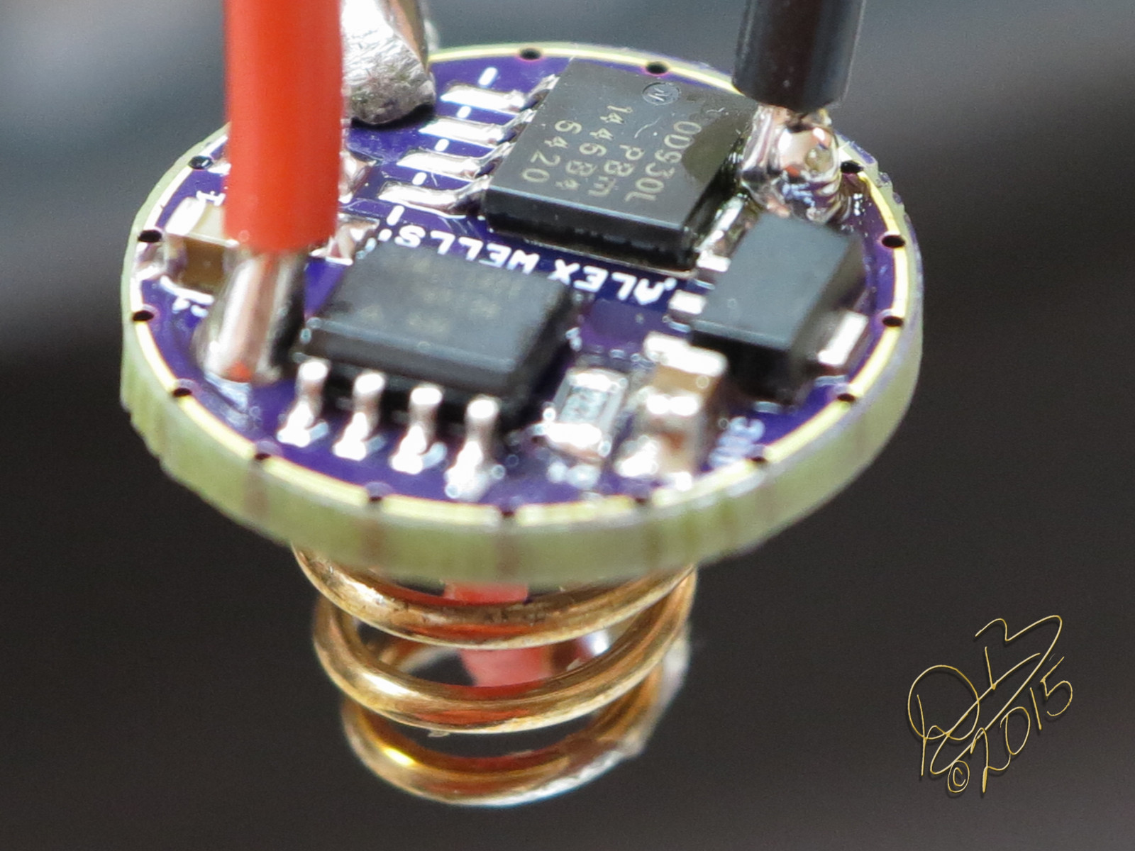
I put 20ga wires on the driver, got some pics of the driver and the new reflector. Bad news is that the polished McGizmo (it was orange peel, I polished it and quit too early) doesn’t have the output I had before. Drops down to 1418 lumens but has a more defined central hot spot. Tit for tat, as it were. The good news is that the 20ga wires brought up power level a little, not significantly but a little… from 6.53A to 6.67A.

And, uh, well, it would seem I’ve lied. I built ToyKeepers driver with the O9 Mosfet, thought I had used that for mine as well. Mine is the lower O3 model. Oops! But this is actually good news because it’s the cheaper one that will most likely get used. :wink:

Uploading a video library to youtube, will be back…

Can you do back to back tests with the two FET’s to get a good number on power difference?

Dale - your wife must be the sweetest angel in the world OR you are already living in a tent in the backyard and haven't told us yet.

Thanks Dale, so a 22k 1% 0805 smd instead of the usual 19,1k at R1 is whats required to match TK’s calibrated values in this new firmware but still the 4,7k at R2.

Interesting so you got 2,1% Amp improvement going from 22ga to 20ga wire at ~6.5A, that is good to know.

Ii assume you mean the R0 and not O3 otherwise you are using different MOSFET that is not the PSMNO9 or the PSMN3R0?

So am i understanding your video right, did you polish the original stock OP reflector to smooth? the reason i am confused is in the video you show 2 reflector one OP & one smooth, i though you only had one sample? and now i understand why you used 20ga……that already is tight with the reflector.
EDIT now i get it, a McGizmo is a reflector from another light, so you still have the stock OP reflector, please check what lumens readings you get, from the 2,1% more Amp improvement you got from the 20ga wires.

How did the smooth affect the throw?

I agree that a back to back test of the 2 FET’s would be very interesting :wink: and that it is good news that you are getting this good numbers out of the cheaper one :slight_smile:

@bugsy36, there is a lot of worse things a man can do as a hobby than flashlights :stuck_out_tongue:

The A6's stock reflector is the one on the left.

I would like to order one! NW please :smiley:

I’m missing things, somehow. What else is new though, right?

Ok, let me start with some corrections. A little earlier, when I rewired it, I actually used 18ga leads. That is why I thought to take pics because they’re huge! So the amperage gain came from a considerably larger wire.

Also, I read the numbers on the MOSFET and misunderstood what I was seeing. That one in the pictures actually is the PSMNO9, same as what ToyKeeper has. So, to preserve the argument, I built another driver using the PSMN3R0 so we could see what the cheaper MOSFET does.

On this one, due to the sheer thickness of the 18ga leads, I used 20ga leads. Confusing, right? lol I shouldn’t have, should have stuck with 22 as that’s probably as large as we could feasibly get them to use. sigh

Anyway, new driver, 3R0 FET, 20 ga leads, same phosphor bronze spring, same bypass. (well, a new spring but the same thing) The cheap FET still does 6.53A off the freshly charged LG HE-2 cell, which is good for a start value of 1604 lumens out the front. This is going back to the stock reflector for continuity with what we can expect to receive from the group buy.

Cajampa, the slightly smaller diameter McGizmo 18mm reflector that I got from Illumination Supply a while back, polished by hand, does indeed have a tighter hot spot that is more defined. Throw? Well I don’t think it’s actually going to show better throw as it’s losing some output…a wash as it were.

I should probably look into figuring out how to put all this information in a spreadsheet so the differences and tried options can be more easily seen. Not my specialty, but I’ll see what I can do…

A better look at the A17HYBRID-S with 18ga leads and the PSMNO9 MOSFET…

Please add my name for one CW, one NW light.

Just a quick note…

As soon as production samples arrive, the code will get recalibrated to match. I wouldn’t count on any particular resistor or value staying constant through this process, but I have to assume that at least the production samples and full production run will use the same hardware.

please add me for a CW also!

i will compare them (NW and CW) and will give away the one i do like second best :smiley:

If a battery-side solderable star doesn’t happen, we’ll see what we can figure out.

In DBCstm’s picture above, the MCU is the blurry chip on the near side of the driver. The solderable star would be connected to the third pin there, and you can ground it by connecting it to the outer ring a couple millimeters away. Conductive paint (or even maybe a thick pencil line) can do the trick if you don’t like soldering. But I’m hoping we can drop a via from that pin to the other side of the board, to make it easier to access.

If there’s no star though, I already have code written to make both options soft-configurable. The issue is that it’s 50 bytes too big to fit unless I turn off some other feature.

Hmm, yes this got a little confusing :smiley: but that how it goes sometimes :slight_smile:

Ok the good news is that 6.53A and 1604 lumens is still a more than respectable output for this little light, but the bad news is we can’t know how much of the loss it is from the cheaper R0 FET or the thinner wires……

But i guess one could say the more expensive FET gives 2% more Amp with a 2ga thicker wire, so probably only 1% more by itself……thats less than i was hoping for, and really not a big deal :wink: but i will probably be buying those anyway :smiley: i just can’t leave potential performance on the table……sometimes i wish i was just more practically inclined and not so enamored with the hot rod aspect of it all :bigsmile:

Good to know that the 18ga actually fit even if they where tight, or did they fit with the stock reflector? the video only showed the McGizmo reflector fitted, i just want to know if 18ga fit or if that is the reason you only used 20ga for the R0 build.
You didn’t test the O9 with the 18ga and stock reflector light right? theoretically if you got 1659 lumens & you add 2% to that you get 1693 lumens :bigsmile:

@TK, do i understand things right that grounding out the 3 pin however it is done in the end, with this firmware would be enough for the memory option, and that you have an user configurable non mem or memory option coded that works, from within the UI but you can’t fit it without possible taking out some other feature?