OK, the first thing we do requires no disassembly of flashlight.
We insulate the pill……
Here is how it is done.
1. Cut a 1 inch plastic circle [washer] from a milk jug [or something plastic].
2. Put a 1/4 inch hole in the middle of the washer.
3. Put this over the spring in the body of the light [where you install the battery]
4. The washer should fit over the spring, help it if you need to.
5. This will insulate the bottom of the pill & keep the battery from potentially/probably shorting against it.
The picture below shows the plastic washer installed as it should be.
RobertB wrote: Yup, easy peasy. Just cut circle out of a plastic milk jug and stick it in. .
[you can also use the 18650 adapter as a circle template. trace around it with a sharpie.]

picture by:RobertB
The next steps will require some disassembly of the light……
So if you do not know how to take your COMETA apart, watch this video, by ‘Jeansy’; until you do:
Please note: Pay no attention to the tape on the pill in this video, I am positive that would work great; but that is not what we are doing. We are keeping this simple and doing one proven “fix” for each problem.
Alright, if you are to this point you now understand how to take your COMETA apart.
The picture below, provided by ‘JamesB’; shows one disassembled.
Please Note, IMPORTANT: There is no need to take the Lens & O-ring out of the Bezel unless it is broken or you need to clean it. When you screw the Zoom Ring out of the Bezel… leave the Bezel pointed straight down on a flat surface and screw the Zoom Ring right out of it. Just leave it laying there without moving or upsetting it and it should be lined up and ready to screw the Zoom Ring back in when you reassemble. Do all of the above with the light in the Full Focused orientation.

Far left is Tailcap
Then starting at top and working down we have Body of Light, the Pill , the Anodized Disc.
Move to right and back to top working down we have the Zoom Ring, the Bezel
Sitting on white paper is the Lens with an O-ring on it.
Please familiarize yourself with these parts and their relation to each other.
————————————————————
Alright, now we know what is what.
Tailcap / This can be taken apart but there is no need to for our purposes.
Body of Light / Holds battery, nothing to disassemble, has an O-Ring on tail cap end.
Pill / Houses MCPCB & Driver, disassembly will be discussed later.
Anodized Disc / Screws onto Body of Light opposite end of Tailcap. Surrounds LED.
Zoom Ring / Fits over Body of Light, refer back to video if you have questions.
Bezel / Houses Lens & O-ring, screws onto Zoom Ring
—————————————————————————————————————————————————-
Alright, now we know what just about everything is and how it fits together.
The next potential problem is the Anodized Disc touching the LED MCPCB solder joints.
When you unscrew the Anodized Disc from the Body of Light and remove it you will see what is illustrated in the picture below provided by ‘RobertB’.

It is the LED mounted on the MCPBC installed in the Pill , which is screwed into the Body of Light. The white part that says BLF KRONOS on it may be red and say NOCTIGON on it. One of mine does.
———————————————-
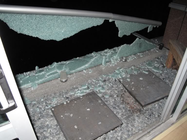
The photos below, provided by ‘goshdogit’; show what to look for to see if the underside of your Anodized Disc is contacting the LED solder joints.


In the top picture you will notice the flat spot on the Negative - solder joint of the LED MCPCB.
In the bottom picture you will notice the shiny looking smear, on the slanted part under the hole; of the underside of Anodized Disc .
These are certain indications the Anodized Disc and Negative - …. in this case solder joints have been making contact.
Typically, but not always; when this happens with the Negative - solder joint only…. the light will be stuck in High Mode.
If it happens with the Positive + or both + & - at the same time you will have a potentially dangerous situation.
If I remember correctly, it was ‘goshdogit’ who first discovered this problem way back in this post on 30 April 2016. You may bead about his experience here. WARNING: Cometa – read/fix BEFORE inserting battery - #1109 by goshdogit
_This problem needs to be fixed. If you ask 10 people how to fix it you will get at least 15 different answers._ 
Therefore I am not going to tell you how to fix it.
I am going to tell you how I fixed it on all of mine though, and it has worked well for me on each one.
However you choose to fix it is totally up to you.
———————————————————
I used this ButterFly Insulator/Spacer. XP-G - XP-G2 - XP-E2 - Plastic Butterfly Style Emitter Spacer / Insulator
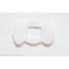
This piece snaps over the LED Die.
It is designed to fit the footprint of an XP size LED.
This piece is 16mm wide & 0.8mm thick.
It is installed with each end at 90 deg. to solder joints.
It is not designed to cover solder joints.
It will raise the Anodized Disc 0.8mm the thickness of the ButterFly
This gives more clearance between the Anodized Disc and the solder joints. In fact mine no longer touched at all.
I then covered both + & - solder joints with Kapton Tape.
I used Kapton because I had some.
Electrical tape or Liquid tape will work just fine on the solder joints also.
If you use Liquid Tape, let it dry 24hrs. to be sure it is dry.
Before I put the Anodized Disc back on I did two more things.
I lifted the MCPCB from the Pill and visually inspected what I could see of both wires. I was looking for cuts or nicks in the wire insulation. I found none in any of my lights. If you do find a nick or cut that is down to bare wire, you need to fix it.
I also put more thermal compound under each lights MCPCB. None of my lights had the amount I personally like. I added Arctic Silver 5 under the middle of each lights MCPCB. The amount I added was about the size of 2/3 a grain of rice. [ best I can do on that one ]
Each of my lights now transfers heat very well.
After adding Thermal compound, if you choose to; push the wires back through the Pill and the MCPCB back onto the Pill with mild pressure to distribute the thermal compound if you added some . Make sure the wires go back through the MCPCB & Pill cleanly & free without being in any type bind.
We will now reinstall the Anodized Disc. Screw it back into the body being careful to make sure the ‘4 teeny humps’ on the Butterfly around the XP LED come cleanly through the hole in the middle of the Anodized Disc. This will center your LED perfectly. Then just tighten the Anodized Disc snugly.
While the light is apart clean it well with a lint free rag or a unused coffee filter. they are lint free
Make sure you get out all the little Aluminum chips, left over from machining; that you may find.
Lube the light with. I use Super Lube, for my purpose it can not be beat. It will not harm Silicon O-Rings either.
Re assemble the light and have at it.
There is one potential problem I have not addressed yet. It involves taking out the Pill,
—————————————————————————————————————————————
Alright, here is the last problem area that can be addressed. [ Heck of a lot of “problems” for a new light isn’t it……  ]
]
The Pill must be removed for this.
We will start here with the light disassembled
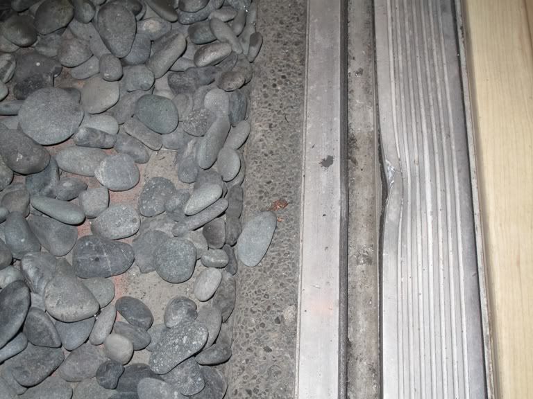
The picture below is the Body of Light with the Pill installed.

Use a pair of needle nose pliers to remove the Pill from the Body of Light as shown in the video.
The red arrows in the picture below by ‘unknown00101’ show where the plier tips go.
Turn counter clockwise to remove………

Be careful not to let the pliers slip and damage the LED, this can happen if you are not careful.
When you break the Pill loose, screw it out. I will come out easily and look like the picture by ‘JamesB’ below.

What you see here is the end of the Pill that houses the driver. To loosen the driver put your plier tips or snap ring pliers into the two holes in the driver retainer ring seen above one hole is hidden behind the spring
Turn counter clockwise and remove the driver retainer ring. This will free the driver.
The Cometa Driver is seen in the picture below by ‘JamesB’.

Where the problem is that due to the fact that BangGood substituted a 17mm driver instead of the spec’d 22mm driver and that the sloppily machined driver pocket is so oversized the 17mm driver could possibly shift to where the positive connection + to the driver shorts out against the Pill creating a potentially dangerous situation.
A sure way to “fix” this is to cover the positive + connection, especially on the edge of the driver; with Liquid Tape. Let it get dry before reassembling the Pill. Also before reassembly inspect wires for nicks or cuts, if any are found cover them with Liquid Tape.
Reassemble of the Pill is the reverse order you diaassembled, trying to keep the driver centered best as possible in the oversized driver pocket; as you reinstall the driver retainer ring.
Then continue to reassemble the light in the reverse order you disassembled.
Well, there ya’ are, that is all you have to do to “fix up” your brand spakin’ new light………… :person_facepalming:
I hope this helps some of you….