I would like to build a big silver convoy with SBT90.2. The L2 host is available in silver, but Simon told me that the 12A FET he uses in the L21B SBT90.2 doesn’t fit the L2, also if I understood correctly, I need a buck driver to reduce the voltage from 2 batteries to 3v.
So there’s a few possibilities/questions:
Find a Buck driver that fits L2 and can run SBT90.2 on 2 batteries in series
Find a FET driver that fits L2 and run with one battery only (short tube)
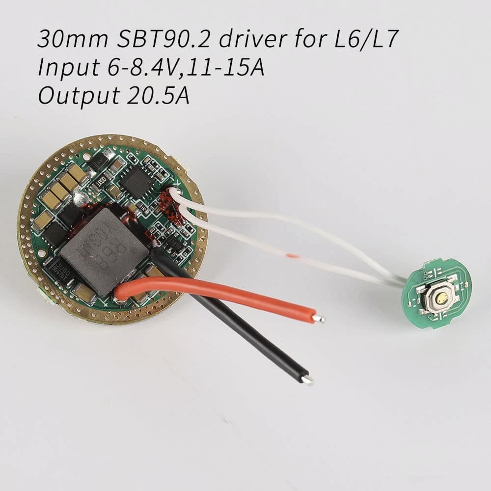
Use L6 silver host and L6/L7 driver: https://vi.aliexpress.com/item/1005002899574569.html?gatewayAdapt=gloMsite2vnmPcglo2vnm
Question concerning this driver: What would happen if I ran it on a single battery with the short L2 battery tube?
a) Run normally as the voltage from a single battery is enough to provide 3v.
b) Running but lower brightness due to limited amps.
c) Not run at all
d) something else? If so please explain.
At this point, the easiest would probably be to ask Simon for the L6 host with the driver mentioned above, but I prefer the look of the L2 battery tube and the flexibility to run with one or 2 batteries, even if one battery would result in lower brightness. So here’s the main question again: what would happen if I run the L6/L7 SBT90.2 driver on a single battery?
Ah, interesting, can you please explain in more detail about the nickel dendrites and why it will explode? If I understand correctly, even unprotected cells have certain safety mechanisms, like venting for over-pressurization to avoid explosions.
It seems like a driver with low-voltage protection would see that the input was less than 6v and stop drawing, rather than exploding, right? And I expect all Convoy drivers to have this feature unless otherwise indicated.
Sure, no problem. Basically the situation involves acyclic nickel-cobalt chains (valency bonds) reacting with several elemental propagators (diatomic catalysts) which, when rapidly synthesized, yields a particularly spectacular deviation from expected normative behaviors. Synchronous rectifiers, when operated out of spec and out of phase, introduce a kind of flyback loop of doom, where electrical oscillations grow in intensity exponentially, in some cases creating highly reactive interstitial compounds within the cell. This reaction occurs between manganese anions and linear chain isomers specifically, which then break their electron chains with the nickel molecules, after which the nickel fires out dendrites with such force as to penetrate the dielectric barriers within the cell, resulting in explosion.
This seems like a great detailed scientific explanation. Is this what you expect to happen when using the driver OP mentioned with a single-cell? Or would low-voltage protection prevent it?
Well I got a chortle out of it assuming you were being humorous.
Engineering toolbox lists of materials properties is such a rabbit hole of pointless information for me, “oh the density of benzene is 878.9kg/m3 iiiintereeeesting…”
Oh ok I get it. I think? No I’m still confused. Where is there an L2 tube for sale? Is it that “26650 L2/L6/L7” tube under accessories? That doesn’t look the shorty tube to me.
You know, if that’s really a 20.5mm driver space you may actually be able to get the 12a FET driver to fit in there if you trim off the edge. Maybe. No guarantee.
I asked Simon about the 12a FET and here’s his reply:
“that driver is not suitable for L2, The dimensions and electrical parameters are mismatched.”
I wouldn’t mind running L2 on one battery, also I wouldn’t mind sanding a 12a FET but I don’t know if the height of the 12a FET will fit in the L2 head. Does anybody know if these dimensions are ok?
I don’t want to keep bugging Simon with these questions…
Idk, but component height is 2mm, and the diameter of the solder masked part of the driver, like if the ring was sanded right off, is 19mm. So 1.5mm to work with if you sanded it to 20.5mm. On the 17mm drivers you have <1.5mm on all of them