I’ve waited as long as 8 weeks for stuff from over there but 6 is about average. You may get them yet. All I have are black, orange, and gitd.
I did some fiddling with microscopic leds two days ago, here's the result. Forgive my limited insight in electronics, it's just trial and error here.
I had a blue and a red led working in my EDC-light (post #280), with the red always on and the blue fading to off between 3.9 and 3.8V, giving a useful half-drain indication. I wanted an extra indication a bit lower so I ordered some yellow leds as well, they have about the same Vf as red, but together with a small schottky diode in series, stealing 0.2V, I reckoned I could get in between red and blue. So a third path was needed on the tail-board and since there were no traces for that I just made the yellow circuitry floating in air (my solder skills are improving by the day :-) )
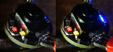 (stereo picture)
I got it working but like the red one, the yellow led failed to go off at any battery voltage. Then I started swapping resistors for other values, but apart from achieving a better balance between the three colour intensities, it did not change the voltage sensitivity of the yellow led. I tried swapping the yellow led for a white led (an Oslon Square 3500K 80CRI I had around, it is nice and small), but that hardly gave any light at all in this set-up. So I swapped to yellow again and called it a day. I will try with a normal diode next time I feel like testing this out a bit more. The current resistor values: bleeder R: 680 Ohm, R for blue:5.6KOhm, R for red 22KOhm, R for yellow 5.6KOhm (+useless Schottky diode).
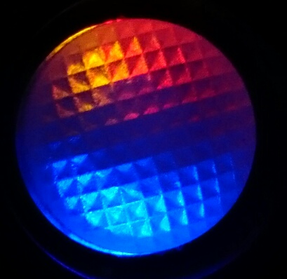
So for now I have three colours from the tail of my EDC, and I can just measure the output: 0.0003 lumen. Sounds like nothing but believe it or not, in pitch dark it is just enough to light my way. So a thing to do in another light is make a permanent moonlight in the tailcap, I have a 3200K 95CRI 5mm led that might be perfect for that :-) .
Oh wow Djozz…
Nice djozz!!
cnqualitygoods.com is down and out - get a MySQL error every time - same ol dependable RIC  . Is there another web address for his site? Cant' recall - fancyflashlights.com doesn't work either. Any other possible source for the transparent button caps?
Thanks, order them. Hope this goes well - RIC is still being RIC, not responsive if anything is wrong, not on BLF in 3 weeks, see here: https://budgetlightforum.com/t/-/33403. Think he got my orders right about 1/2 the time, either wrong or missing parts - I gave up asking him to correct it.
@djozz: Have a look at these circuits: http://www.talkingelectronics.com/projects/200TrCcts/101-200TrCcts.html#22
There are a few variations where you have separate red [, orange] and green LEDs, but I think the best solution would be the one which uses a dual red and green LED. Orange can be obtained from enabling both red and green phosphors.
I think this LED (or similar) will work nicely:
http://www.kingbrightusa.com/product.asp?catalog_name=LED&product_id=APHBM2012SURKZGC
http://www.digikey.com/product-search/en?site=us;lang=en;Keywords=APHBM2012SURKCGKC
Do you think it's possible to have a nice green -> orange -> red battery indicator in the tailcap? Some modifications to the circuit will be required, but I think it will take this project to a whole new level
Thanks, I'll dive a bit into that :-) My first impression is that those electronics forum circuits do not care much about space, and space is not abundant on a switchboard to state it mildly. I think the way to get a voltage indication that actually measures voltage done is to find a tiny dedicated li-ion voltage indicator chip with outputs for several indicator leds, and then ask PD68 politely to make a switch board that accomodates the circuitry for that.
I think we could possibly fit this in but may have to have a stacked board.
Or we have some of the components sitting under the switch?
it could fit but there's trouble with the need of the bleeder resistor on the driver, it can not become too low or there's too much current bypassing driver+led when the flashlight is switched on. Or would that resistor not matter for how this works?
If you guys figure something out, I’d be glad to do the work in Eagle.
Thanks! I think challenges are to find out how the bleeder resistor fits into this and how this circuit translates into (available) tiny SMD components, and I'm not an electronics geek. I understand resistors, leds and diodes, but which (sot23?) transistor to get I have no clue, anyone?
I was fooling around with This idea back in 2012 but didn’t know about eagle then and it’s still a space hog unless we can find a smaller quad opamp but it would give up to 4 - step accuracy.
Edit- Post 23 of that thread has a hand drawn layout for reference. It uses a sot-89 voltage regulator for chip power and a sequence of voltage dividers for the comparators.
This is the chip I bought for this.
Here is the circuit mentioned in the linked post. 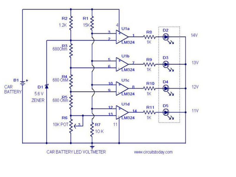 The resistor values can be adjusted for different voltage steps and I think I did those calculations already.
They look like they will take up a lot of space. Ideally we need to get it to fit under the switch between the two pads.
(edit: it seems like the minimum is 6V for this to work)
I found this, with no further link to the chip:
The Simple-Volt automatically detects the number of LiPo cells connected (assume charged pack) and continually monitors the battery voltage and compares it to the preset cutoff/warning voltage corresponding to the number of detected LiPo cells (9v for 3s, 12v for 4s and 15v for 5s... basically, 3 volts minimum per cell). When the battery voltage is greater than the cutoff voltage +1v, the Green LED will be on solid. If the battery voltage is > cutoff voltage+.5 but < cutoff voltage+1v, the Green LED will slowly flash. If the battery voltage is > cutoff but < cutoff+.5v, then the Red LED will begin flashing. If the battery voltage < cutoff voltage, both Green and Red LEDs will flash very fast while also emitting an intermittent beeping sound from the peizo alarm buzzer.
Drop the buzzer and use smd parts that could work, could sit the chip under the switch and use a 4 layer board for the traces.
Ahhh 6v min… maybe not.
I'm not too fond to put a chip under the switch. In 9 out ten flashlight builds that gives space problems in the tail section...
I'm again looking at the simple circuit with the BC547 transistor. I was looking for that transistor in SOT23 package and could not find it, but the BC847 in SOT23 is easily available: I know squad about transistors, would that one work too?
edit: no answer, so I looked it up myself :tired: : BC847 is the SMD variant of BC547 so I'm good here. I ordered three on ebay to play with. I'm doubtfull if the bleeder resistor messes the circuitry up though.
I wouldn’t think so maybe it would squew the voltage reading but I doubt by much, we can always adjust the other resistors
Thanks, that gives some hope! When the transistors are there I will make an 'air' circuitry with all components in place, if that works well enough we can ask pd68 to do his Eagle-magic on the tiny board :-)
BTW, I ordered the BC847 in SOT-323 package, so even smaller than SOT-23, we may just need that for the real board.