I could send you a build one… I may have one still assembled.
I would definitely not complain. ![]()
At 19mm I doubt it’d fit in any of my current hosts, but it should still work fine for testing purposes.
I built a TAv1 with OTSM (Bistro-HD) last night with a 500 ohm BR, and a rev 5.1 tailcap with a 63k ohm resistor on each of the 3 channels. It’s almost perfect, but occasionally short presses are interpreted as medium presses (opposite from the usual problem I have with these tailcaps).
Any idea if I should I try more resistance or less on the bleeder to fix this? It’s kind of a pain to replace the BR on this board, so I thought I’d ask here first.
**Edit: The answer was no bleeder at all. I didn’t even think to try it without one present.
Yeah, the lack of bleeder should, if anything, actually make OTSM work better. It thrives on not losing power.
Any recommendations on where I can a buy a 0805 SMD 560 ohm bleed resistor?
I usually buy mine in those combo packs with lots of different values, just so I’ll have options on-hand. You can get those lots of places, like Amazon. But if you know that one is what you need, and only that, you’d probably be best off with one of the big parts houses, like Digi-Key.
I’ve gotten some from eBay (US sellers) or from Banggood if I’m not in a rush.
Looks like I can get 20 0805 SMD 560 ohm resistors on eBay for $1.89 from a US seller. From reading this post, it appears that should do the trick to resolve the Bistro firmware issues I’m having with the MTM 17DDm FET + 7135 Driver and the Astrolux SC/SS BLF X5/X6 Flashlight Lighting Switch. I plan to put it between the spring and the retaining ring, shown below with a green line. Please let me know if you think I should use a different resistor or do something else.

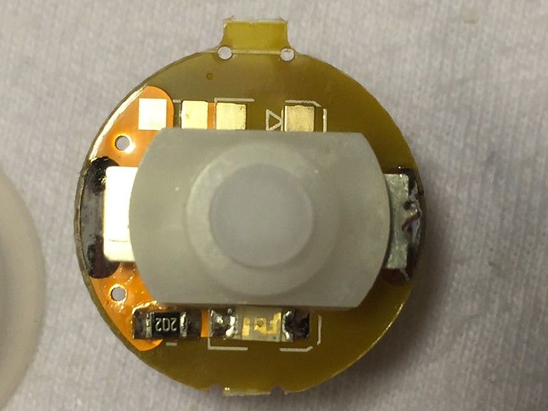
Overall I think your plan is sound. Placement looks good and your value is logical, at least. If I were you I’d order a few different size bleeder resistors just in case though. There’s not a lot about these mods that’s black n white, and sometimes it takes a different value to achieve the desired results. But you could get lucky on your first try.
Good advice emarkd. When I looked at the variety pack from Fastech (0805 SMD Chip Resistors Value-Pack (400-Piece) ) and Banggood, they do not include a 560 ohm resistor. They instead include the following: 10Ω, 22Ω, 47Ω, 100Ω, 220Ω, 470Ω, 750Ω, 1KΩ, 2.2KΩ, 4.7KΩ, 6.8KΩ, 10KΩ, 22KΩ, 47KΩ, 75KΩ, 100KΩ, 220KΩ, 470KΩ, 750KΩ, 1MΩ
So closest would be 470 or 750 ohm. Is that close enough?
Mostly likely it would be fine. I’ve used those same 470s in lots of builds. Its a difference of about 20% though, so your parasitic drain when the light is on would increase by about 20%. Not that that’s a lot, but its not zero. But then if high efficiency is your goal these taillight builds aren’t really that anyway.
I’ve also had good luck with 680 and 750 ohm bleeders, but those were with the Gen2 boards.
The 0805 won’t be long enough to bridge where you have the green line. But you can scrape away some solder mask on that large area at 12 o’clock and solder it between there and the spring.
…or just “drag” your solder to fill the void. It’ll stretch across there pretty easily.
I thought a 0805 SMD resistor would be better to use than 1 of those carbon film resistors that I can get from my local Radio Shack (a 5 pack for $0.78). I should be able to stretch the solder to make it work, but I’m open to other ideas.
Looks like I may have gotten lucky. My youngest son likes to save electronic parts that he takes apart at school. I looked through them and found this.


I am curious about this since I had bought a convoy s2+ clear with lighted tail switch. How much power does this light in switch consume? And does this bleeder resistor they call drains the battery even there is no led on switch?
Here’s what I found out. This was not a fun process, but in the end, worth it. I started with 2 0805 SMD resistors, a 220 and a 470 ohm in series, so 690 ohms. I was able to solder them together and then solder them to the spring and the retaining ring. It looked great and it appeared to work. I was able to medium press back between the modes, but the off time memory was screwed up. When the flashlight was turned off for an extended period, it would turn on in some random medium or high mode. So I used 2 220 ohms resisters and tried again. And again I got the same issue. I then tried to solder a single 220 ohm SMD resister, but was not able to bridge the spring and retainer ring. Then I used a 328 ohm carbon film resistor, and it worked!


Hi i want to convert the bad switch construction in this light (Did you know this Host? - #15 by TheOnlyDocc). I would like to use pilotdog68s design. But the available PCBs did not fit. Now i want to ask if you would help me to make two new PCB for this light? I have the measurements ready but i have not decided on the switch. I am waiting for BanL to get me the info i need( i would like to use this one (http://www.kaidomain.com/p/S024079.DIY-LED-Flashlight-Reverse-Clicky-Switch-12mm-x-12mm-for-LED-Flashlight-Black-button-5-pcs) but if it is not high enough i would have to use a KAN28. It has nearly the perfect hight.
My original torch (the top LH solarforce shorty with the green cap in the first post) has been working perfectly since I put it together. It runs almost two months before it fully drains an 18350.
My wish list would be to find a way to fit a converter so we could run EL Wire instead of surface-mount LEDs, but those things require about 100v up-converted from DC to function.
~D
I have been thinking of using EL wire in a flashlight, but what has put me off trying it is what the cheap (few $ from Gearbest) EL-wire with driver does, that produces a pretty loud and annoying high tone. Are there versions that do not do that? (perhaps uses a higher frequency for generating the high voltage)