And voltage spikes from the FET, when only the 7135 is on?
I remember the problem (with the Attiny13a) that PWM-0 is not completely off and PWM-255 is not completely on. Perhaps there’s still influence from the FET even when it’s seemingly off. That might explain why the 7135 is now degrading slower.
But sounds like a case for a scope.
I will happily make you any board you need for this beast (vias, GNDring, single double triple channel, snubber, coil, C for 7135…) but I need specific data. Me no EE, I just happen to make some brd in eagle…
It's weird, but not sure it's getting worse, but yes - FET hasn't been turned on, at least PWM of 0, and still this odd behavior of the 7135.
I switched to a regular "4 mode set + moon" now, and it's working normally - moon PWM 3, PWM 30 on 7135, PWM 255 on 7135 -- all working fine. There's no mode memory so must go in this order. It works fine, just like ramping when it ramps through the PWM levels on the 7135, it always seems to work ok.
The only problem in ramping is when it restores the last used PWM level, and the level is in the 7135 only.
This is what 0.1 lumens moon mode looks like, not much more than glowing:
Ah, the mythical 7135 - Who know what the real specifications are…but this is definitely something worth testing.
Most of the 7135 datasheets do not mention anything, but some ADDtek datasheets show this Cout and state that it is needed if the emitters are not on the same PCB as the 7135. This one for example have it as ‘strongly recommended’:
On page 4 they detail that it is needed if wires are longer than 3 cm. Seems 1 uF is a good starting point.
Cout is not going to play nice with the FET PWM (probably also the 7135 PWM!), so it would be for a quick test only.
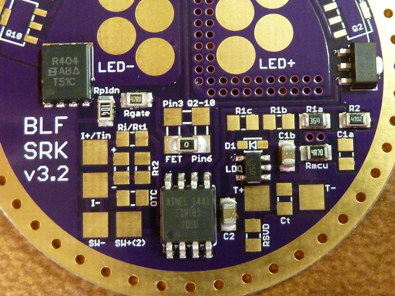
Other thoughts. Tom is using phase-correct PWM so 0 is fully off and 255 is fully on. So this is probably not the FETs doing. (But might still be what killed the original 7135). What does the LDO circuit look like HQ? And do we have the correct LDO part/pinout TOM? Would be good to put a multimeter on the LDO while testing. Critical for most LDOs is the size and type of the C at the outlet of the LDO. Would expect the MCU to be more sensitive to an unstable LDO, but who knows…
C1 and C2 are both 10 uF -- think this was proper way to do the LDO?? I'm 99% sure this is the LDO that is "DEL recommended" , I hope?? Pretty sure I got these LDO's from Arrow, after you or HQ gave me the exact part#, I believe - at first I bought the wrong ones. Arrow's order history is broken so I can't confirm right now - I'm at work so don't have access to the LDO parts. Dunno if that "L250" label on the LDO means anything. Hhmmm - ok, was discussed in HQ's thread here: https://budgetlightforum.com/t/-/40540.
I know I did not guess in choosing the LDO myself - used one previously posted/used or recommended. I do not trust my own knowledge of this stuff at all.
I thought I was told using a 10 uF cap for C2 would be the way to go with an LDO. Is this correct? I see the circuit in the data sheet is fairly complicated w/parts.
LDO is the pinout mattaus/wight used, I detailed in this post
It wasnt me who proposed a certain one from arrow, I buy them locally.
I tried 2 different LDOs (will post nr from home) and one did not work. I tracked it down to what might be that the LDO needs a minimum output load. Couldn’t find it in the datasheet, just read about it in the web. Second one works, but I only use it on the 11+1 driver, not on the SRK FET.
C size for LDO: i looked up more than 2 datasheets and afai remember they want ~1-2.2yF minimum and there is almost no restriction to go higher. I use 10yF for both as well.
For future reference, this is the LDO mentioned in HQ’s thread:
Both this and the Micrel you used look like very good parts. Low drain, reverse polarity protection, good C2 compatibility. 10 uF C2 should be perfect for both. This one does something with pin 4, where it is N/C on the Micrel. N/C is fine for both.
The Micrel is specified to be no-load stable.
Looking at the LDO and general board layout nothing seems off…mystery.
Probably a stupid question, but is C1 rated for 8.4+ V?
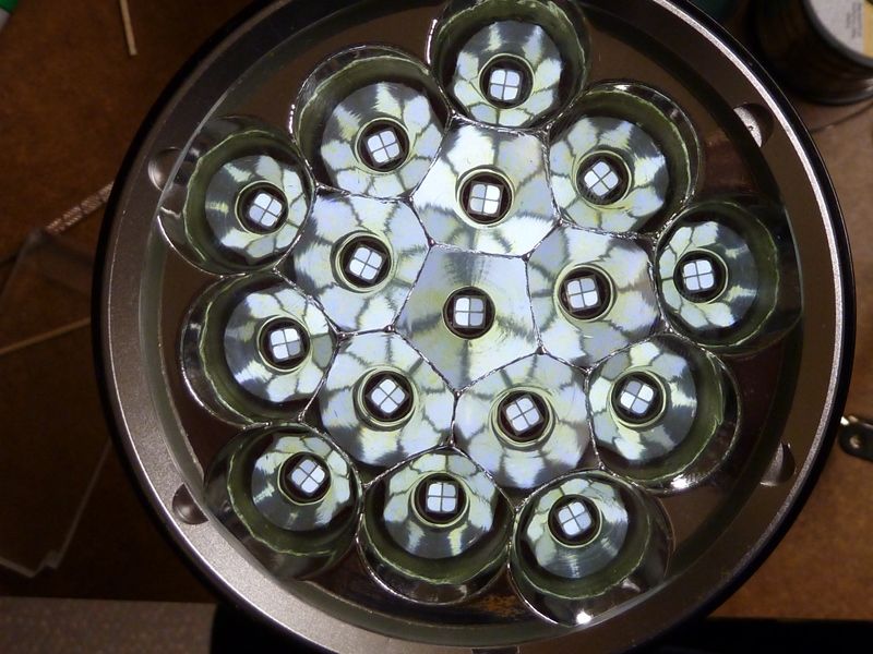
It took forever to ship and my sample should be fresh stock / current batch. The retaining ring for the button is red on mine and the spring board green. The rest seems to be the same as in the Fasttech photos.
My expectations were very low, but it turned out better than expected. No shelf behind the mcpcb, way off-center LEDs, aluminium bezel, whimpy driver and wires (26 AWG?!), but not bad for the rest. The host is a little different from the traditional, no fins around the button and a 6-lobe design on the tail cap, vs. the 3-lobe. Decent reflector, real XM-L2s, cool but not blue. Reflowing the LEDs to center properly was easy enough.
I considered to do the typical add-in shelf and using loose 16 mm dtp mcpcbs, but decided it is not worth the time. Running the light at 5 A for a while showed the thermals to be better than expected as well. The 3-4 mm rim below the mcpcb transfers heat surprisingly well. The head heats at about the same rate as the mcpcb. After 15 minutes everything was at around 55 C with the loose (and driver-less) head driven directly from a power supply set at 5 A CC.
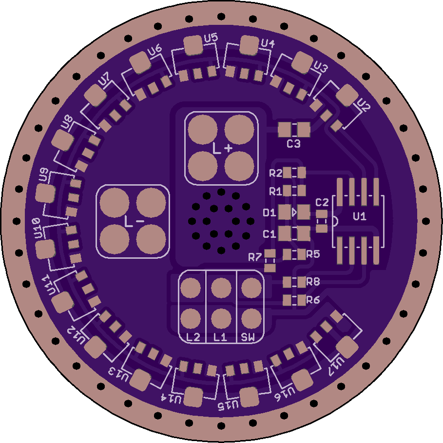
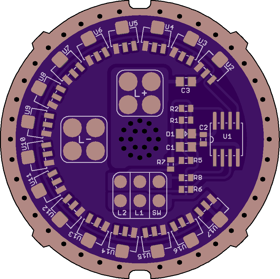
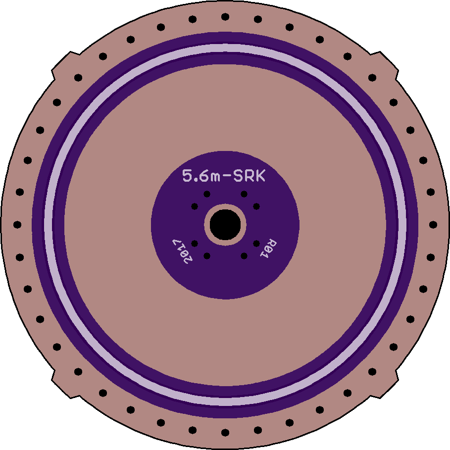
So this will become a ceiling bouncer/cell holder for camping/power outages. No DD, but rather a simple 2-channel current-limited driver with space for up to sixteen 7135s:
Similar to the K2 driver above, there are resistors and pads to drive up to 2 indicator LEDs. These are not useful with the stock Ultrafire clone.
Ahh, not stupid Q at all. I dunno... Typcial 10 uF cap, probably the one Richard sells that comes from Mouser, or ones I bought from Arrow - not sure. Gotta check.
The first LDO I tried was a TPS76950, which simply did not let the light work properly.
Then I ordered other types but I’m not 100% sure what I ended using. I believe it’s the MCP1755T (I still have in my box LD2981 and LP2985 as well). All are fixed voltage 5V versions.
The driver board for cheaped-out SRK lights is shared. The pads for the 7135s have been up-sized to regular SOT-89 pads (most of the smaller diameter drivers use cut-down pads to save real estate on the PCB). To allow routing without vias the thermal pads are still not full size, but should be ample and are fully connected to the ground ring.
No FET, no DD. It should be a good match for the sample cheap SRK I have, even using the stock non-dtp mcpcb. There are probably worse ones out there that will still need thermal improvements for this to run well.
The pads for the lone 7135 on the K2 driver are now full-size as well (rev01).
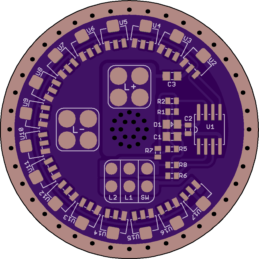
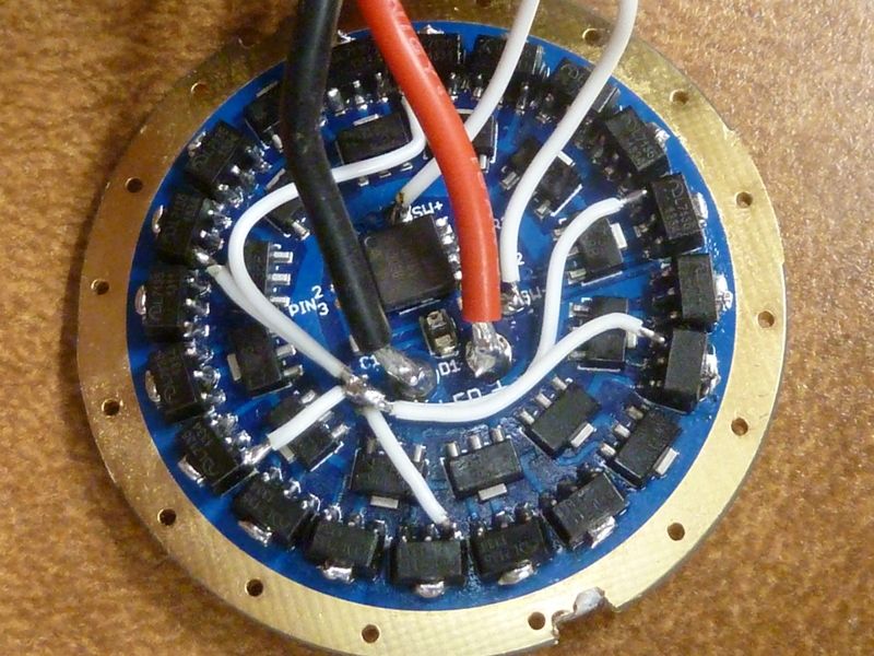
Dang, this is a nice 5.2A SRK driver... Good match perhaps for the DBSAR SRK lantern project. For me, I'd be too tempted to stack 7135's though . But certainly based on this design, no need for these jumpers which really did pick up the amps on this design (and maybe because of stacked 7135's), but all these jumpers were not needed, just 1 or 2:
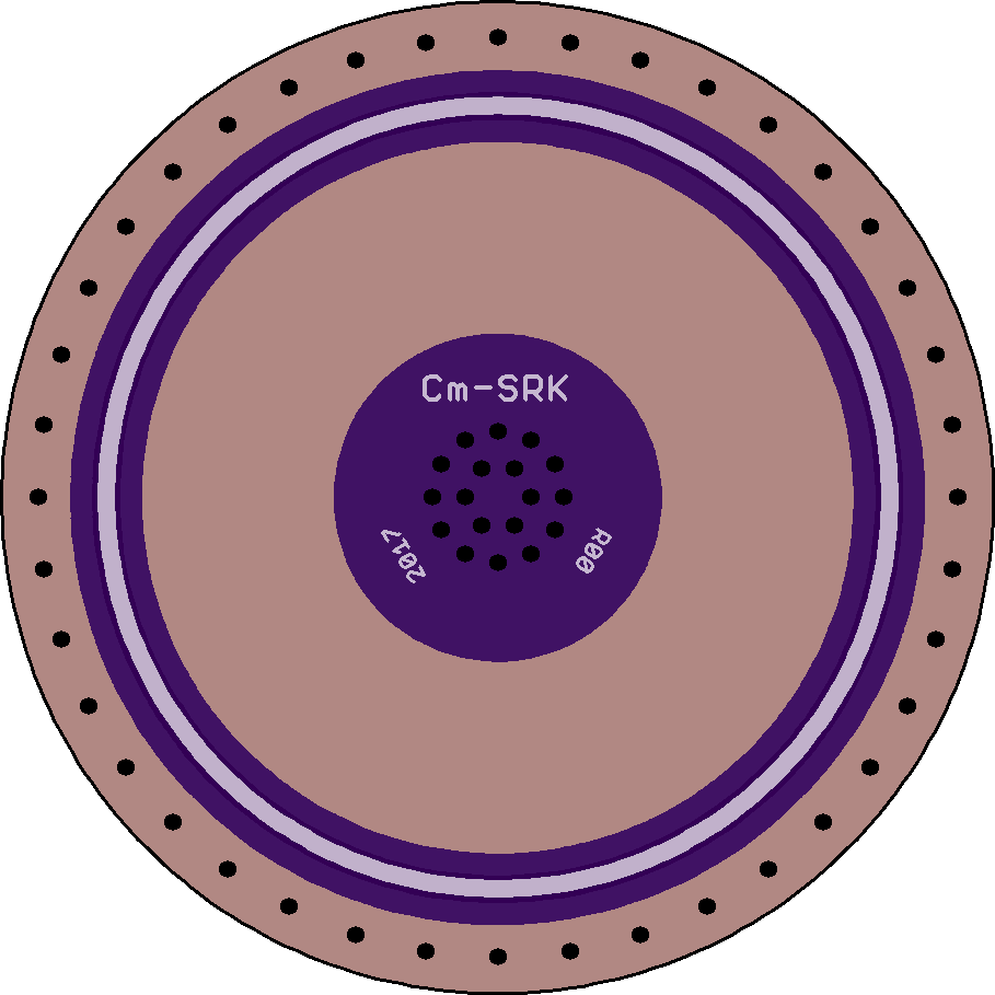
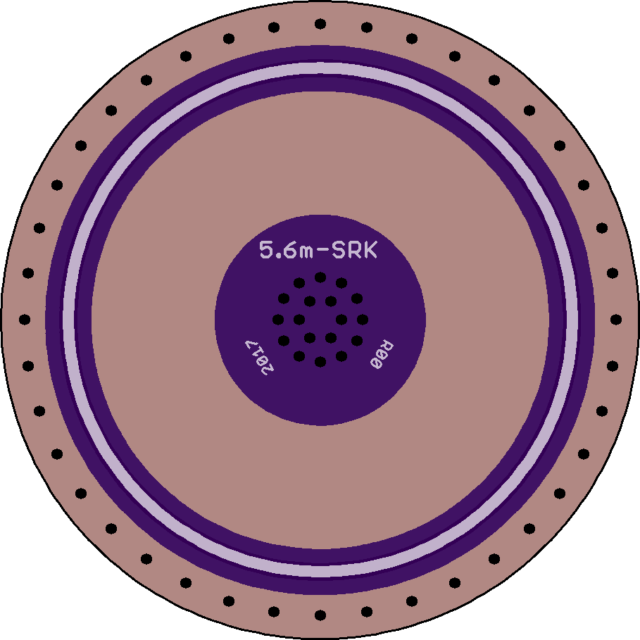
I also added the pry holes on the edges to help removing from a tight press fit.
Yes, this board should not need jumpers (stock build anyway). Generous tracks everywhere, a luxury not available when fitting 32 of those 7135s.
I actually did consider adding pry-holes and maybe the typical sand-to-fit side tabs. Both are easy enough to add if useful. Was thinking to use dabs of silicone caulk to hold the board. Access would then be from the front to push the driver out if needed. Not an option on some builds of course.
Ahh - funny you should mention that use of silicone caulk. On Tuesday I took your L4 board and expanded it's width a little using a 2 part clear epoxy because I really needed a 26mm board, but the L4 extended a little bit will fit snugly, and still get a good ground contact. I trimmed the epoxy to be flat aligned with the top and bottom of the PCB.
I do like the tabs - sometimes you do need that extra material for a good press fit. For the pry holes, there could be a better solution. You need a good tool to use them without scratching up the threads (I've done this), then you could break thru the anodizing on those threads which makes intermittent electrical contact when screwing on the battery tube. Many of these cheap SRK's though have poor thread anodizing anyway, so maybe not so much an issue.
Not sure how to do this better - maybe couple enlarged ground thru holes, or maybe couple large holes little further in from the edge so it clears the underlying ledge? Really not sure what the best way is, but should match up with an appropriate tool. I've used a pry tool with a hook or bent end - seems to work best. Hard to avoid some light damage to the PCB. Most people won't be popping these in and out anyways.
Yes, the pry holes were useless on the Ultrafire host that started this. The board was jammed in tight and I think there was some superglue involved as well.
The pry holes on the OSH board above are oval/flat, to be used with a flat 90-deg pick. Or a cheap flat screwdriver with a bent over tip. Round picks would damage the PCB.
A nice option would be a hole, off the ledge as you say, with a small nut glued over it on the component side. The board can then be pulled easily with a bolt screwed in from the back when needed. Would be easy to change the center +vias to one large via for this purpose.
Very very nice features on that board.
Now I’ll be the one to start some borrowing
I really like the tabs. Less material to remove if not needed, but probably even better contact as it makes for 4 contact points. And: no extra cost because they are put diagonally and do neither increase width nor height.
Has anyone noticed how the tabs and the 7135 match with the alignment of the GND holes? I’m a big advocate of form follows function, but those details really get me.
Pry holes. Real pita when you don’t have them… Although even a present cutout makes it difficult to get the board out in an SRK. There’s simply not enough leverage. But 2 opposed cutouts… and long pointed pliers… and turning instead of levering… I need to test this.
Oh, and routing LED- on the inside of the 7135 instead of underneath them. I had this on my first draft of the BLF SRK V3, but decided against it for better routing of the PWM signal. But the more I look at your board the better I like it, even if PWM goes between 2 legs of the rightmost 7135.
Thanks HQ, happy if you find something useful in there! The 7135s are placed on 18 degree radials starting 45 degrees from east. The vias are on 9 degree radials.
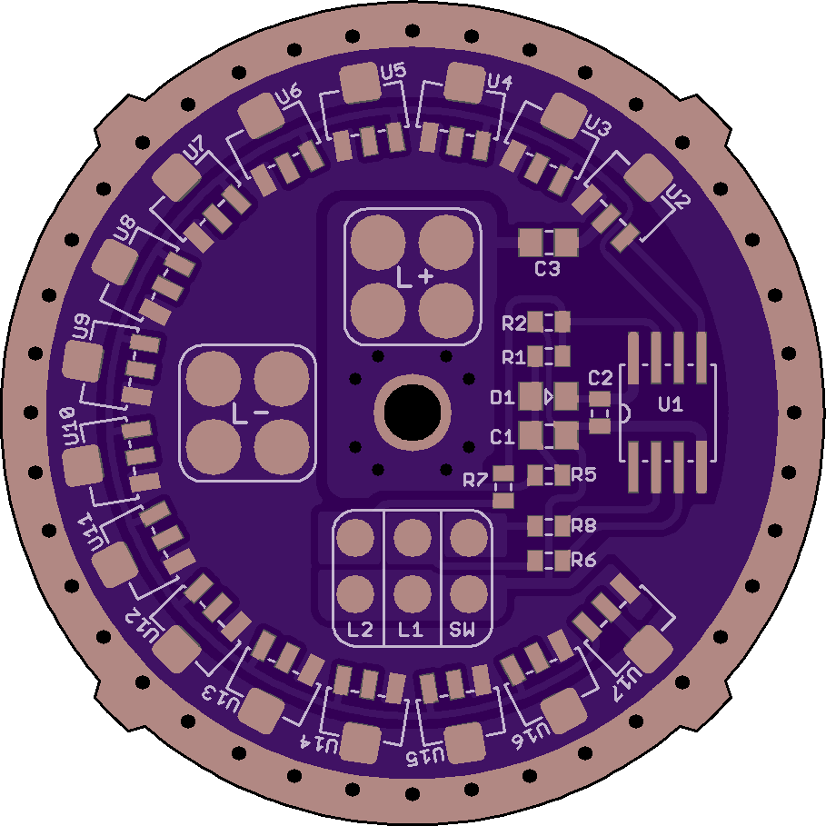
There was a small bug on the version with tabs though. The top two and bottom two round segments of the outline had a radius that were a little off. Fixed now in rev01a.
The stock board had 2 round pry holes. I had no luck trying to twist them, but I did not have great pliers in that diameter either.
This version has a center ‘pull-via’, to be used with a glued nut as described above. Off-center would probably work better, but not really space elsewhere for it.
 , I hope?? Pretty sure I got these LDO's from Arrow, after you or HQ gave me the exact part#, I believe - at first I bought the wrong ones. Arrow's order history is broken so I can't confirm right now - I'm at work so don't have access to the LDO parts. Dunno if that "L250" label on the LDO means anything. Hhmmm - ok, was discussed in HQ's thread here: