After checking into several of the Chinese light bars, Ive decided that Id be far better off building my own for roughly the same cost. Although many of them advertised high lumens, and several of the off road community bought them and posted good reviews, they still appeared to be severely under driven and cheaply built. All the ones I could find were glued shut. A destructive disassembley using a ban saw revealed a single large mcpcb with all the emitters and a cheap small driver surface mounted to a large cheap board. Even worse was the extremely poor thermal path to a cheap undersized heat sink running the length of the backside of the unit. Sure, the sink gets hot after a few minutes, but by that time the internal board is running far hotter and frying the emitters and driver components. The reflectors were plastic with a dull cheap finish that probably cut 20-30% of the lumens. Also, only single mode high and no thermal protection. The Chinese must make an absolute killing on these from those that dont have anything to compare them with (other than their OEM headlights).
My DIY search began by looking for a driver that could power a large XM-L array with integral features to resist the transient spikes from an alternator. Having securing a local source from DIWdiver for the driver, I found a pair a massive aluminum heat sinks on ebay (20 lbs each). One will be used for the light bar.
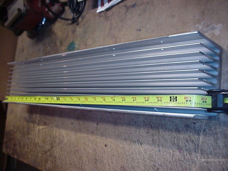
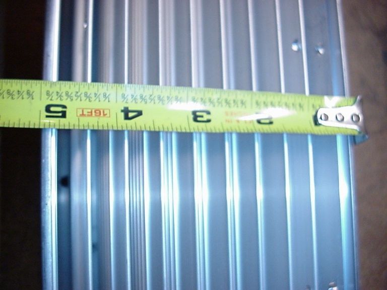
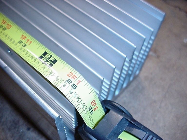
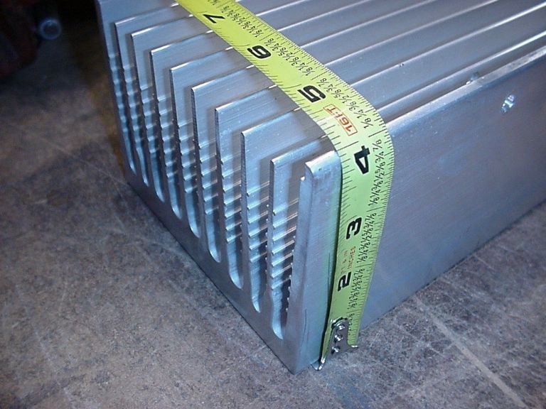
The heatsink measures 25.5” x 5” x 4”. So the mounting surface is 25.5” x 5”.
The driver is a linear mode design. The closer I can run the LED vf to the actual input power and maintain at least a +.2V differential on the input side, the more efficient the driver will operate. If vIN falls lower than vF, the driver will fall out of regulation and the lights will dim… nothing catastrophic to worry about. Since the alternator will already have to contend with 27 amps from the LEDS and 16 amps from the pair of 100 watt HID’s, plus power the vehicle (probably around 10 amps), this puts me at around 53 amps total continuous. The aux lights are on a relay and toggle. When the relay is activated, it kills the headlights and activates the aux lights. I wired it this way because the stock headlights contribute nothing when the HID’s are activated. I will add additional switching options and relays to individually select any combination from HID, LED1 high/low and LED2 high/low. More on this later.
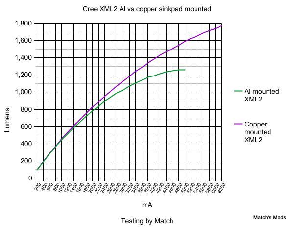
Ive already ordered a bunch of Noctigon mounted XM-L2 U2 1A for this project. The array will be wired through two independent drivers and each driver will run 20 LEDs in a 4S5P config at 13.5A total output per driver, or 2.7A to each emitter. After checking out Match’s emitter tests, it looks like this config would allow for the lowest vF while extracting the highest lumens.
A few extrapolations in different configs (4S4P versus 4S5P and different drive currents):
XM-L2
3A = 1125 x 32 = 36000LM (4S4P 12A total)
3.375A = 1220 x 32 = 39040LM (4S4P 13.5A total)
2.7A = 1040 x 40 = 41600LM (4S5P 13.5A total)
From Match’s tests:
With a great deal of help from Old-Lumens and a lot of digging, I think Ive finally concluded that I’ll use 40 x C8 smooth reflectors. A combination of different reflectors would complicate the build considerably because of their different mounting heights, so I think I’ll just stick with one type for now. The configuration will be a 3 row or staggered reflector pattern. Since most C8 reflectors are 42mm, this leaves something of a dilemma since 42mm x 3 converts to 4.96”. Thats cutting it a bit to close for a 5” wide sink. I think Ive found some C8 reflectors that measure 41mm, which will give me a more comfortable 4.84” to work with.
For the reflector config, Im considering:
Row 1 - 13 emitters
Row 2 - 14 emitters
Row 3 - 13 emitters
If anyone has any better ideas, please let me know. I wish I had some modeling software to test different configurations.
If I have cooling problems with the sink, I can fabricate a plenum to scoop air from either side of the sink, force it through the fins and eject it out the back of the center of the sink. I wont know how hot it will run till I try. The driver comes equipped for H/L mode operation activated via an optional on/off/on toggle, but can also use a rheostat for infinite control. I havent decided exactly which direction I’ll take at this point. There’s room in the cab to install duel amp meters, so a rheostat for infinite brightness control for each driver + dual amp monitor might be an interesting option. A temp probe might be mandatory.
I’ll update when parts begin to arrive. If anyone would like to play with some modeling software to help me optimize the reflector placement, that would be a REALLY big help.
Specs:
40 reflectors measure 41mm each
Reflectors must be in 3 rows, stacked or staggered, as long as they remain symmetrical.
Sink surface is 25.5” x 5”.
Any comments and suggestions would be welcome. Im probably already well over my head, but this is nothing compared to a few mega high output builds Ive completed in the past… its just different. :bigsmile:

