Doming a flat LED to adjust CCT and tint

Dedoming a 519A to lower the CCT and duv has been a popular mod since the emitter’s initial release. A natural question to ask is whether the process can be reversed: starting with an LED that is too warm and too pink (which is the case with many FFL/NTG emitters), could adding a dome to it make it more neutral in both CCT and tint?

If this works out, it would mean that

  • All overly-pink domeless emitters are easily tint-correctable to pretty much any duv-value the user desires. Given that most manufacturers are deliberately trying to make LEDs on the magenta side, this modification provides an abundant source of neutral-tinted emitters.
  • Rare CCTs too fine for the usual 1000K or 500K increments can be easily achieved. Any domeless 4000K emitter can now take the place of the discontinued 4500K 519A. Additionally, the upcoming LHP531 R9080 in 3000K, 4000K, and 5000K can easily replace emitters with intermediate CCTs like 3500K, 4500K, and 5700K.

Today I’ve decided to try this out with a SFT70 3000K. Despite the HB4 bin, the tint is a bit rosier than a truly neutral halogen lamp, and the spectrum strongly oversaturates reds. I would like to make the light a bit cooler/whiter and correct the tint.

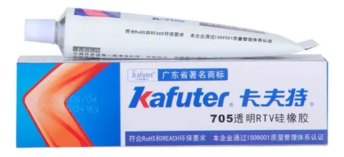
The only material you need is a tube of Kafuter K705, a clear sealant often used for potting. It’s $5 on Aliexpress for a giant tube and has essentially unlimited shelf life, making it a superior alternative to LED Seal, which MtnElectronics used in the past for finishing off XP-G2 dedomes. This material is also easily removable after curing–I first attempted this mod on a W5050SQ5 3000K and afterward removed it without damaging the phosphor.
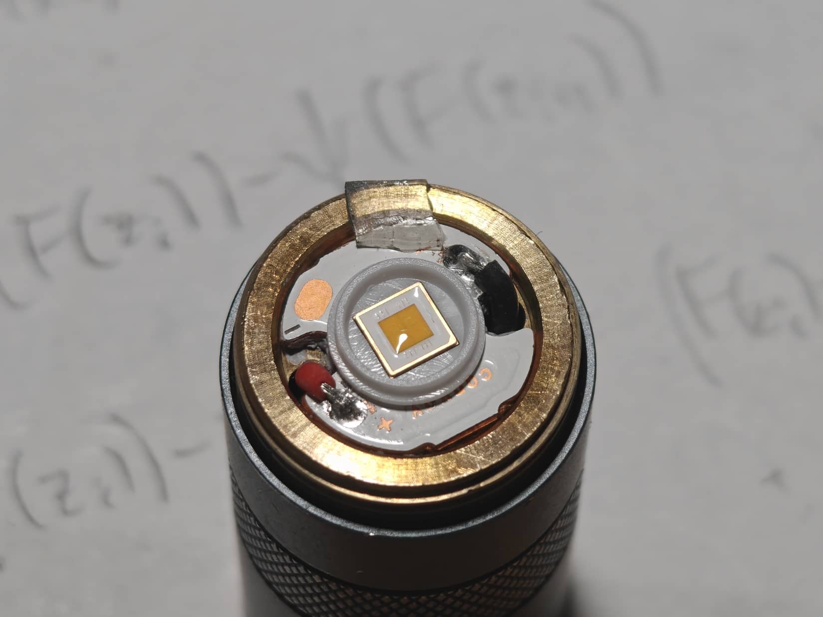
I used a plastic toothpick to carefully cover the phosphor with a thin layer of sealant, less than 1mm at the thickest. I covered only the phosphor to avoid introducing angular tint shift and losing any throw. After letting it cure for a few hours, this is what it looks like–notice the shiny reflection on the phosphor!
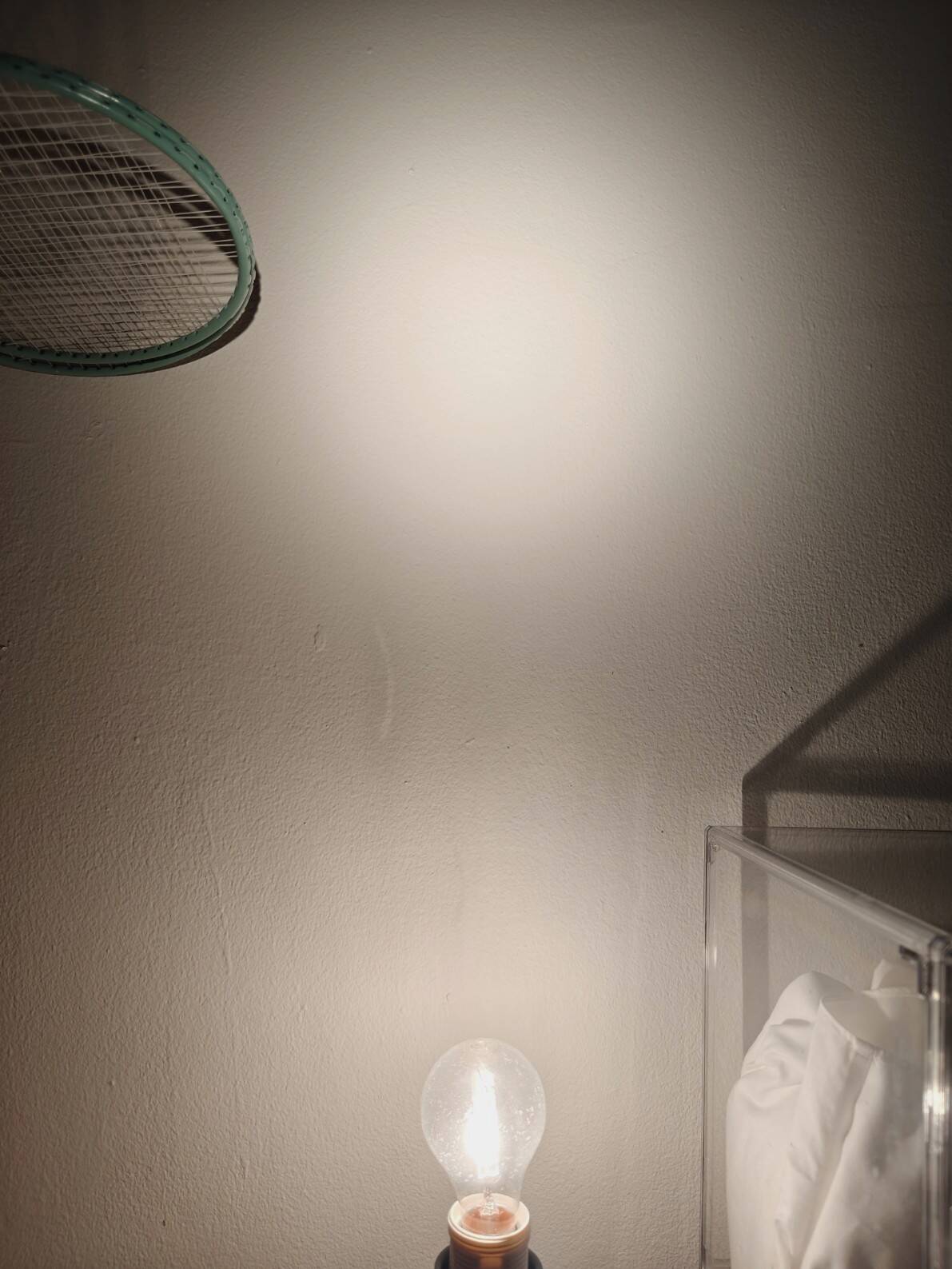
Here’s a (not very controlled) comparison between before and after, next to a halogen lamp. The camera struggles with CCT–the actual CCT difference between modded SFT70 and halogen is more pronounced IRL.

And compared to an unmodified SFT40 3000K:
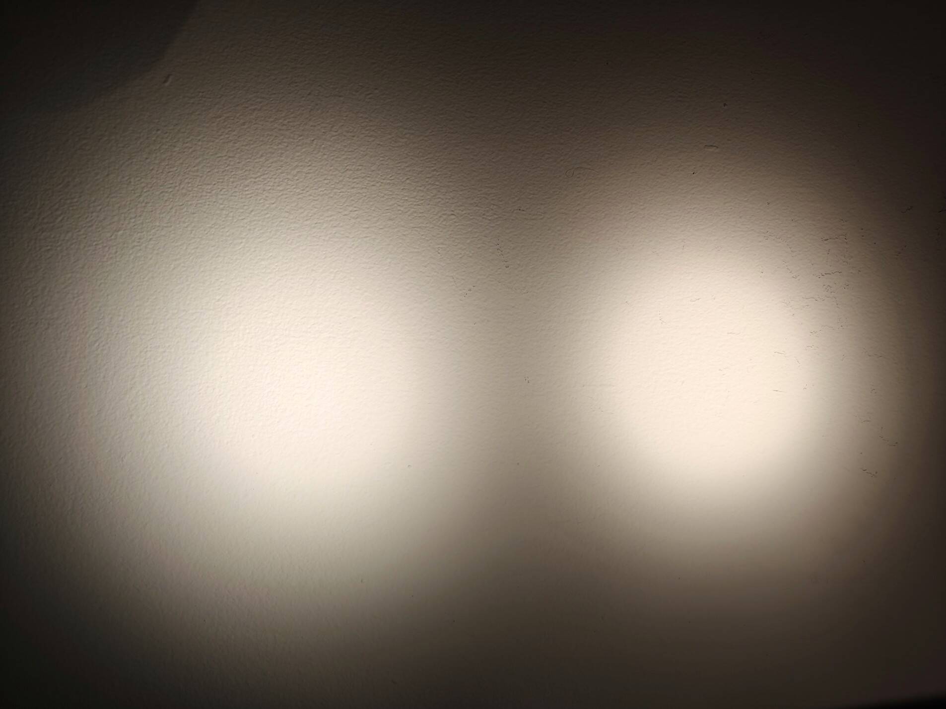
The modded emitter is now completely neutral, and cooler by about 150K. This doesn’t sound like much, but does make the beam noticeably whiter/cleaner. Keep in mind that this is after only a thin layer of Kafuter–if one were to actually make a full dome out of it, the effect would be much more pronounced. I stopped at this point to avoid making the emitter greener, since it is already quite neutral to begin with. CRI visually feels unaffected or improved–reds still remain oversaturated, but all colors feel slightly clearer. This is now my favorite emitter!

Note that the same spectral modification affects the CCT more at higher CCTs. Assuming that this doming modification changes the color by an additively-constant number of micro-reciprocal degrees (mireds), the same modification that takes 3000K to 3150K would take 4200K to 4500K (thus turning an overly-pink NTG35 4200K to a neutral 4500K), and take 5000K to ~5430K (thus turning a domeless rosy 5000K emitter into a 519A 5700K replacement).

Finally: while CCT always increases, whether the duv increases or decreases seems to depend on the emitter. My experience thus far is that high-CRI emitters generally see an increase in duv, while low-CRI emitters generally see a drop (which is what happened to the W5050SQ5 3000K I tested before the SFT70). This is consistent with old XP-G2/XM-L2 dedomes having a greener tint than pre-dedome.
24 Thanks

Wow, this is awesome!
Great work.

5 Thanks

This is pretty cool, I would love to try this with dedomed 5700k 519a’s. They Opple out to 3800-3900k at lower levels and hit 4100-4200k at higher levels. A thicker layer of that Kafuter should bump it pretty damn close to 4500k.

2 Thanks

I’ve also tried this on 519As, though the results are somewhat boring/expected. Dedoming and redoming produces about the same CCT/tint characteristics as slicing, but does give a better beam because the redomed surface is much smoother than a sliced one.

Give this a shot! You can dial in pretty much any CCT you want between ~4000K and ~5500K. With the 519A this redoming method is especially easy–the existing glass+silicone surface prevents the sealant from spreading excessively while liquid.

3 Thanks

This looks great!

I remember reading on reddit a few years ago of people doing the same thing for certain LEDs, maybe they were sliced or dedomed or domeless to begin with.

As soon as I started reading I remembered there was a product for this, but then saw your product recommendation. I will definitely get some of this and do some experimenting. I have some emitters that I do consider to be too rosy, and I like a bit of negative DUV. Some of the NTG35/50/FL351A/5009R specifically the 3500K 5009R. It is insanely rosy, I mean it’s actually just straight up pink. IIRC Jackson’s measurement (Opple 4) were like -0.023 or something.

This is very interesting, I forgot it was even a possibility. Absolutely gonna order some of this, Thanks!

Interesting SFT-70 results. I have two lights with it, a Noctigon KR1AA and a Convoy M1. It’s a bit greener under the KR1AA TIR than it is the M1 OP reflector, even though the KR has green ARC glass and the M1 has uncoated. I would not call either beam rosy, but the M1 reflector one is a bit closer to BBL than the KR1AA TIR.

I have read that TIRs lower DUV and reflectors raise it, but this has not been fully true in my experience. My DM11 and D4SV2 TIR optics make the light more green, from just barely to very much so.

SFN60 in the D1K was absolutely purely clinically cool white with absolutely zero hint of green whatsoever, but under the DM11 TIR it was just as green as your average 6500K W1 or SFT-40.

The D4SV2 TIR turned slightly rosy (at higher current) DA bin 5000K SFT-40 to quite green, but the same LED under the Acebeam P16 was slightly rosier.

D4SV2 turned mostly neutral 4500K 519A into unusably green.

These last few paragraphs could be off topic, but it’s just something I’ve been noticing. I think I will try this stuff on some dedomed 519A first before the FL5009R.

If one didn’t like the results, is there any way to remove or dissolve the stuff? Maybe something like CA glue debonder, but I kinda doubt that would do it, and it might damage the emitter. Or would it just peel off?

Thanks for this interesting post topic!

3 Thanks

By doing this, you should also get a small boost on luminous flux

2 Thanks

Actually now that you mentioned it, I vaguely recall seeing someone try to glue back a severed 519A dome. The nice thing about building a dome from scratch is that you get full control over how thick to make it (and thus how much CCT/tint adjustment you get).

Previously to this, I’ve been messing with UV resin for the longest time. It works ok normally, but delaminates itself during reflow, due to thermal stress–it stays super duper rigid even at high temperatures. It can also be sometimes hard to remove–I once tore the entire die off of a 519A in trying to remove a UV resin dome that is bonded too strongly to the glass!

This will probably require many repeated applications to build up a thick hemispherical dome, and even then it still might be too pink!

As stated, the claim is definitely too general. Some TIRs are poorly designed (e.g., Carclo 10509/10624) and introduce even more tint shift than a shallow reflector; in particular, one gets a super green hotspot. Regarding the D4SV2, I recall reading many years ago that they turned the 5700K LH351D so warm and green that people thought they received the 5000K emitter!

Fortunately, Convoy has some very nice single-emitter TIRs that do a fantastic job blending angular tint shift. I strongly recommend the 20mm 5050 TIR in 15deg flat and 20deg beaded, plus the 21mm S21E 5050 TIR in 15deg and 30deg beaded. I haven’t yet found a very good single-3535 TIR.

Yes! With my initial W5050SQ5 experiment, I was able to remove the sealant with light fingernail scratching. The cured sealant is much softer than even the very soft SST20 dome, and seems to adhere to the phosphor physically rather than chemically. No debonder or solvent needed.

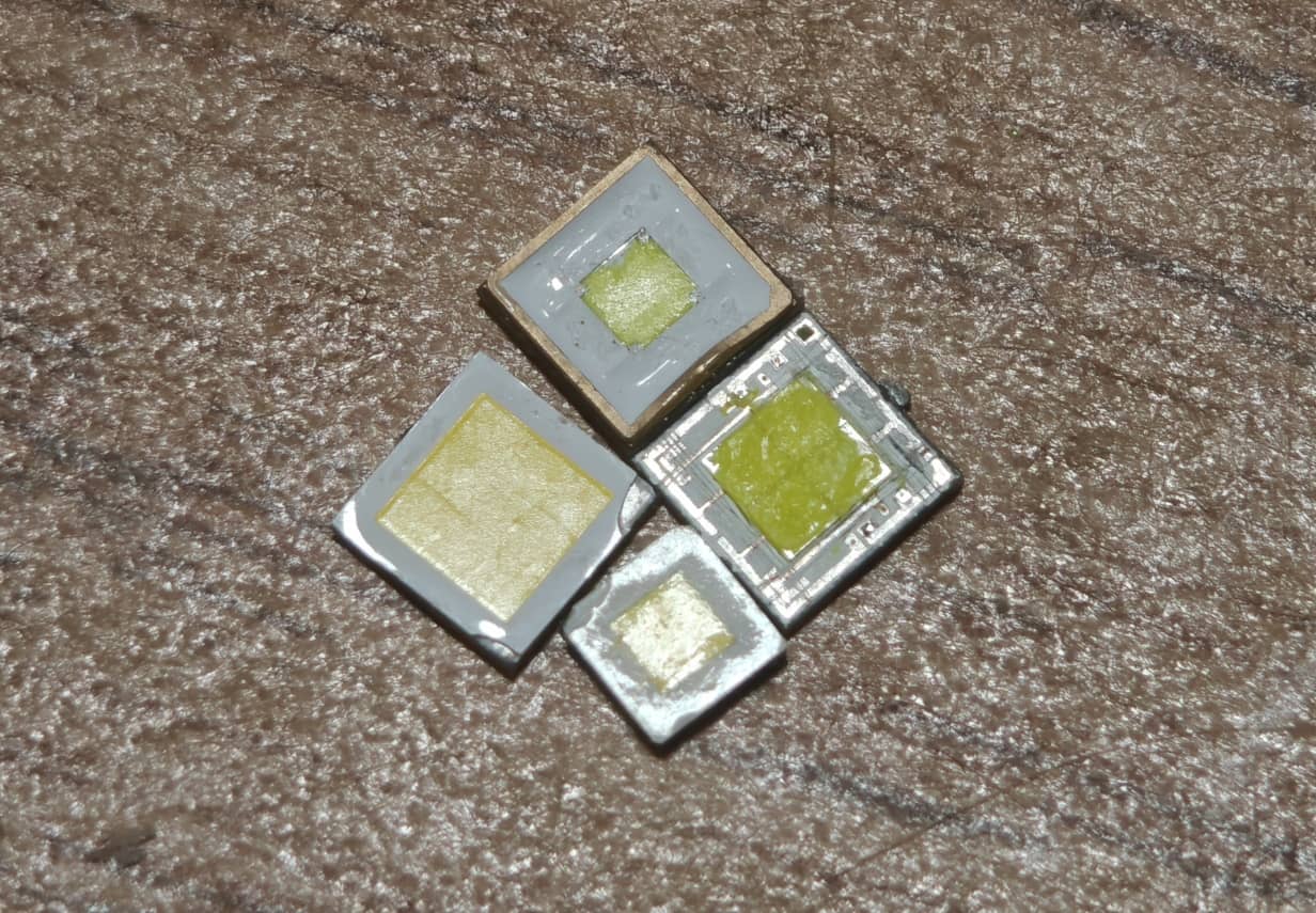
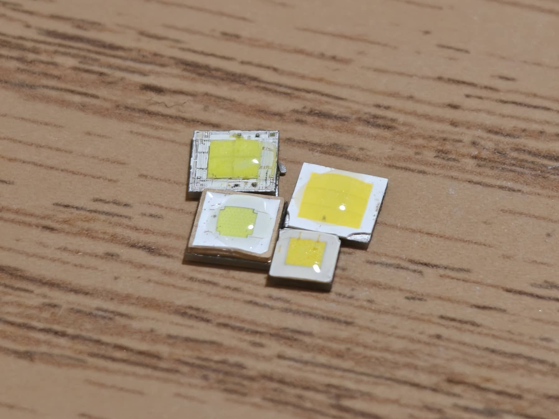
Just to make sure it works equally well on all LED finishes, I grabbed 4 sacrificial emitters from the scraps box to dome: an LHP531 and SFT40 to test the phosphor surface, plus a sliced XHP50.2 and XPL-HI to test flat silicone surfaces like FFL/NTG emitters. Tomorrow they’ll cure, and I’ll update you on how the removal goes.

5 Thanks

Indeed! With some very pink emitters, I believe that CRI should also be boosted, in addition to luminous flux. The increased extraction efficiency really tilts the spectrum in a favorable way.

2 Thanks

Maybe I glossed over it…I wonder what the optical/spectral qualities are…Is it essentially the same stuff that is used on LEDs already?

Is it altering the light characteristics by filtration, added phosphor activation, or some other combination?

Also…How “flat” can you make it? Does it settle flat, or does it have that little “bulge” that water does?

1 Thank

Probably any transparent solid with some intermediate index of refraction would do!

Turns out it’s neither! The shortest description would be that it reduces the average number of times a photon gets absorbed/re-emitted within the phosphor, which means that more energy is retained by the time a photon exits. Hence the shift to higher CCT.

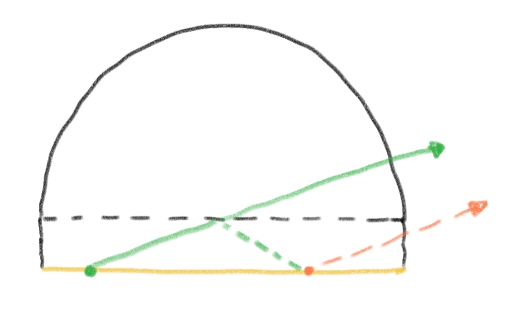
To elaborate more on the mechanism: the main mechanism at play is the thickness+curvature of the dome making it easier for light to exit. Consider what happens when you put a round dome on a flat-domed LED (like XPL-HI):

With a flat dome (dotted black line), the ray of light (green) coming from the bottom gets reflected back to the phosphor by the solid-air interface, due to the oblique angle of incidence (i.e., total internal reflection). Thus this ray needs to be down-converted at least one more time (turning orange) before exiting.

With a round dome, the ray passes through the dotted line because it no longer separates 2 different materials. When it hits the hemispherical boundary of the dome, its angle of incidence is very close to perpendicular, which gives it a good chances of exiting immediately.

For truly domeless emitters (e.g., SFT40, LHP531), there’s a secondary mechanism at play, and a short explanation would be that the added clear silicone material has an index of refraction between that of the phosphor and that of the air, and having this intermediate step increases the overall transmission, due to a concavity property of the transmission function. Below is the long version of the explanation:

Long version

For simplicity assume that all incidences are perpendicular. Given a boundary separating two materials with reflective index ratio r, the transmissivity T(r) = 4r/(1+r)^2 follows from direct simplification from Fresnel’s equations. Note that even though “reflective index ratio” is ill-defined without specifying the order of the two materials, T(r) is still well-defined as it is invariant under a reciprocal transform to the input.

The statement “having an intermediate material increases transmissivity” translates roughly to: for all positive r, s, T(r)T(s) > T(rs). One can reword this as F(a)+F(b) > F(a+b) for F(x) = ln(T(e^x)), which essentially just says that F is concave/subadditive.

It has the same bulge that water does, which should be more effective than a flat surface, per the diagram above!

3 Thanks

Test results are in…

  • LHP531: easy removal. Scratching+tearing with fingernail removes most of it, and a quick rub with a t-shirt removes everything else.

  • SFT40: slightly harder, mostly due to the white substrate being soft, giving you no hard surface to scratch against. I also chipped the phosphor, which was likely preventable with some more patience. With phosphors that are embedded into the substrate rather than elevated (e.g., LHP531), there’s very little risk of chipping.

  • XPL-HI and XHP50.2: hard. The original surface is too soft and gives you nothing to scratch against. I was able to restore most of the XPL-HI surface to a mirror finish, but don’t have the patience to do it fully.

The difficulty mostly comes from the cured sealant being soft and extremely elastic, tending to stretch rather than break off.

My general overall suggestion would be to plan on not removing the dome if you do it with Kafuter, and instead do it incrementally in thin layers, and power on after each cure, to ensure you get the CCT/tint you like. Actually, one has to do it in thin layers anyways because a too-thick layer of sealant tends to spread out and become unmanageable.

For LEDs with an existing flat silicone dome, UV resin is a better material for doming. It does everything a dome needs to do, but is dissimilar enough to silicone that the entire dome easily pushes off.

5 Thanks

Materials matter. A lot. I cannot wear polycarbonate or 1.67 prescription lenses due to the horribly low ABBE value; low ABBE = more chromatic aberration. I prefer CR39 when feasible, as it’s barely below Crown Glass, but it’s mechanical properties make it unsuitable for certain frames. Trivex is a good compromise, especially since it has the same UV and impact protection as poly while CR39 is lacking on both.

TIR optics may use different materials from what I work with, and Bob knows what the ABBE value of some random stuff you squeeze from a tube is, but the fact remains that material matters.

Is it really the design? I can’t help but think that that’s only part of the equation.

1 Thank

Design may be only part of the equation, but I argue that it is the most important part, and the only part remaining after eliminating irrelevant variables.

It might be helpful to remind ourselves that TIR stands for Total Internal Reflection, not refraction. Although refraction does play a role in facilitating the total internal reflection, any chromatic aberration introduced is smoothed out by the large LES, at least for small TIRs; for this reason, angular shift is really about how a particular TIR mixes the light, not chromatic aberration.

Another way to see that angular tint shift does not come from chromatic aberration is to just observe it in a reflector, which has no refractive element at all! Since almost all large TIRs (say, Simon’s entire 20-ish mm diameter catalog) are made of acrylic, the material is not a relevant variable for explaining their performance differences, which leaves geometry/design the only variable left.

From my experience with dozens of different TIRs, I’ve learned some correspondences between design features and beam properties. For example: if a TIR has a large central convex lens (e.g., Carclo 10507), it is less likely to make a greenish hotspot. If the TIR has a way to collect not only lateral but also frontal emission into the hotspot, it is likely to make a tint-uniform beam even with horribly tint-shifty emitters. Convoy’s 20mm 15deg flat TIR accomplishes by making the wall of the emitter cavity a cone rather than the usual cylinder.

1 Thank

Acrylic, acrylic, or acrylic? Or did you mean acrylic? I ask for the same reason I don’t automatically assume an ABBE value for Hi-index as they range from nearly as bad as poly to about as good as Trivex. Likewise, one material I used to cut like butter and one I broke tools on at half the feed rate were both 300-series stainless steel.

No argument there. Our disagreement is simply whether it’s the ONLY factor. Too bad we don’t have TIR optics with the same geometry but different materials to settle it.

1 Thank

I see–it is conceivable that there are different acrylics with different optical properties. All of the acrylic materials I’ve worked with have the property that they are easily damaged by isopropanol, but this is not much identifying information.

After learning that there are different acrylics, perhaps only factor is a stronger claim than I’d actually like to defend–I’d like to think that our disagreement is in the relative weight/influence of the two factors: material and geometry.

I do wish we could have TIRs with the same design but different materials to test our hypotheses. I imagine that materials with different indices of refraction would naturally warrant slightly different geometries in order to ensure that the reflected light is on-axis, but would guess that this difference is small enough (relative to LES size) that the same geometry makes a fair comparison.

One heuristic that I use to inform my guesses is that flashlight optics are not precision imaging devices like eyeglasses and projectors. The latter map pinpoints to pinpoints with no blurring/smearing, and have no tolerance for nontrivial artifacting. In comparison, for flashlight optics, many small-scale artifacts are either smoothed out (say, a 0.5-degree chromatic aberration in comparison to a 5-degree beam) or overwhelmed by more significant artifacts in a flashlight beam (e.g., angular tint shift of the bare emitter).

4 Thanks

I ordered a tube of the Kafuter K705 Clear from AliEx.
I wanna do a torture test on it.
Rudimentary heat and chemical resistance tests.
I’ll work my way up to 50amps with a SFP55 emitter.

7 Thanks

Likely.

A fair bit of my interest in optics is in focusing, which is highly dependent on geometry. A PAL with any appreciable cyl (Astigmatism correction) has interesting geometry indeed. However, we also have a lot of patients that, like me, have color perception quirks that make things many people won’t notice into something that ranges from annoying to medically detrimental.

That makes both factors fairly significant to me at my day job, though likely not in the same proportions as for a flashlight. And even then, the relative weights depend; sometimes it’s worth sacrificing a little visual acuity to avoid triggering neurological issues like vertigo, headaches, or migraines. With flashlights, one really one has to worry about a beam that is less aesthetically pleasing.

2 Thanks

I wish I knew more about the geometry of various aspheric lenses. I’ve only worked with reflectors, which are much simpler to deal with. With lenses, the “angle of incidence equals angle of reflection” rule turns into at least 2 applications of Snell’s law (due to the pair of air-solid boundaries), which is much less intuitive to work with and makes analysis of ray paths more complicated.

I’m quite fortunate to not have this, though I do think my color perception has become more detailed/nuanced after spending lots of time pursuing high CRI in my lights. Lots of really nice emitters like 519A look unbearably pale (in comparison to sunlight or halogen or SFT70) when illuminating certain objects, which is mildly annoying but something that doesn’t impact my health. Though I definitely sense my mental health getting worse living in a crowded NYC apartment with no direct sun through my window.

That’s really interesting to learn! I have the third-worst myopia out of everyone I know, and change glasses pretty often. I can kinda feel the force exerted when my eyes try to refocus to the new lenses, but fortunately no headaches. With flashlights the stakes are indeed much lower.

1 Thank

Interested in the results! K705 advertises itself as being able to survive 200C, so let’s see if it holds up.

I’ve mentioned UV resin as an alternative for flat-dome emitters, and am somewhat curious how it would fare. I think it can easily survive a short burst of high temperature (it survives direct contact with soldering iron), but I don’t know whether it yellows over time.

1 Thank

I’m gonna do a test for yellowing over time. More details tomorrow when the setup cures, but the basic idea is to have a few drops of K705 and UV resin on both sides of a thin acrylic sheet, and leave it out in the sun for some weeks.

The reason for doing both sides is that the acrylic serves as a UV filter and allows comparison between unmodified sunlight, and sunlight with UV content removed. This comparison is important because some sources say that UV exposure causes yellowing, but white LEDs have no UV content.

Very different setting compared to the high power density of being directly above an LED, but hopefully the cumulative exposure adds up. Maybe I’ll do another test with a sacrificial LED that is continually powered on…

1 Thank