Thanks, can you share them in the Eagle Libraries thread for everyone?
edit maybe a Dropbox account is needed to do that.
oh yeah, that’s how I tweaked TexasPyro’s board, it was just the .brd file, and I really like the poly command and it’s ability to auto route the solid pour around wires and vias…very cool
I am learning bit by bit about Eagle…and it’s not as hard as I thought it would be, still an amateur compared to most
I keep seeing way to import eagle components from PDF’s, well have to convert the PDF to something, then import that something into eagle
and others
I have been finding all the .lbr files I can find and getting the ones that most suit our needs, I have a repository already…if anyone is interested
https://www.dropbox.com/sh/i47cuo70drszxud/AACTRLd1pGuv4WKTRruFe_Cea
Oh Mattaus, I also tweaked your CAM processor to include the drills as a .TXT file and make a Milling layer .GML
It is here
https://www.dropbox.com/s/pandmdvdrr8ryaf/Matt_Gerber_Generater.cam
I add all the CAPITAL letter files generated by your CAM file to the .zip file uploaded to OSHPark and it seems to work out just fine (not like it didn’t before)
Plus I can import the files into the grbv viewer and it autodraws a 3D render without the .GML it chops some of the board
http://piratery.net/grbv/index.html
in the colors directory, I copied the OSH.lua, and renamed it to default.lua, now when I drag the gerber files over to it…viola…instant 3D rendering of the board and traces
like this

Hey now that's pretty sweet...
QUestion about the CAM generator. Why the need to add the extra layers? Purely for the 3D view? My CAM generator has always worked fine - never had any problems with boards other than my own stupid mistakes.
Started watching your tutorials today. Very easy to follow. It would have taken me a good amount of time to absorb that much material reading manuals and online guides. Another of many great contributions to the forum. Thank you Mattaus. 
There was a post someone sent to dirtyboards.com or something…they need drills in .TXT format…and just added the milling layer for the 3D thing…they aren’t needed at OSHPark but some board manufacturers use the drills in .TXT format.
I’ve found a cool little trick, you can save your preferred grid settings as a preset then simply select it with a right click.
I’m having an issue, I swapped out some CAP’s in the .sch (removed 0805’s and replaced with 0603’s) but the board wont update, it tells me
“Board and schematic not consistent!
No forward-Backannotation will be performed!
Use the ERC command to get a detailed report.”
How do I get the board to reflect the changes?
edit: I was able to swap out the parts on the board by using the replace command but still wondering why its giving me that error.
Care to share? You can tell that I have become used to a way of working and have not bothered changing out of pure laziness haha.
[quote=Cereal_killer] I'm having an issue, I swapped out some CAP's in the .sch (removed 0805's and replaced with 0603's) but the board wont update, it tells me "Board and schematic not consistent! No forward-Backannotation will be performed! Use the ERC command to get a detailed report." How do I get the board to reflect the changes? edit: I was able to swap out the parts on the board by using the replace command but still wondering why its giving me that error. [/quote]
That's odd. Whenever I remove parts from the schematic it removes them from the board, and adding new parts always puts them on the board. In fact I did it last night whilst revising my Medusa board.
Yeah pulling components from the sch will rip them off the brd, this is why using the “replace” command works so well
On the board, right click component, then use replace
I had to do that with the SOD-123’s I brain farted and put on the BLF15.17DD instead of the correct SOD-323, doh…then possibly a teeny trace extension to tie in the new pad
Hey Matt, could you go through the process of adding a library part again only this time include the unzipping part? The video is too quick for me to see what you are doing. Also, maybe add some instruction on editing an existing library part.
As in another video? Can do when I have time. But if in text...
Adding new library from a zip package:
- Download the part from where-ever (e14 for example).
- Unzip the entire contents to a temporary folder (I use the desktop)
- In Eagle go File > New > Library
- In the new window select File > Execute Script...
- In the window find unzipped contents you extracted earlier, and inside there should be a file name end with '.scr'. Open this.
- The window will now become populated. If you like you can check through the package, symbol, and device views to ensure its the right part.
- Once you're happy, click File > Save As... and save the file into your desired library parts location. Make sure you use an appropriate or easily recognizable name. Saving it as it's manufacturer part number is pretty much useless most of the time because you may end up with 'ERJ-B1AJ101U@E' when in reality 'Resistor 2010 Wide' is much more appropriate 
Editing an existing part:
- Open the existing part via File > Open > Library
- Click on the Device view
- Write down all the connections before you do this. Click the 'Connect' button (bottom right) and in the window that opens hit 'Disconnect' until there is nothing left under the 'Connection' tab. Alternatively if you know exactly what pad/pin combo you want to change you only need to disassociate those items, not everything.
- You can now edit the symbol and package to your hearts content. Just remember to name any pad or pin changes that you alter or remove as you go. I can't really go too in depth at this part as it really depends on what you're changing and how dramatically you're changing it.
- Once you're done with your edits go back to the Device view, and again click the 'Connect' button. Connect the appropriate pins and pads back together.
- File > Save As... if you want to create a new part and leave the existing part.
- File > Save if you're modifying an existing part.
If more detail is needed please ask :)
- Matt
once you have the settings how you want you right-click the grid icon (on my screen directly above the i button) and go down to the bottom to “New…”
A pop-up asking “Alias for current grid settings” will show up, name it there, it will then be at the top when you first right-click the icon for all your boards.
You can do the same thing in the .sch.
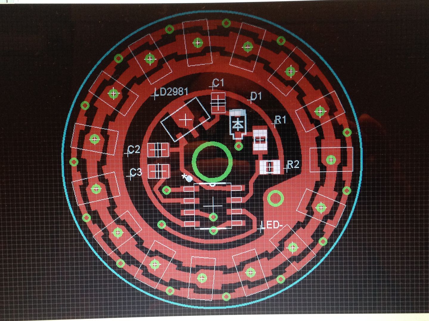
Not finished and already needs changes but here is my first effort.
Top
Bottom.

Anyone care to reveal how to make tented vias?
What is that about a 35mm driver? It looks good, that’s it for? What’s going on with that giant via in the middle?
To mask the specific via’s right click, go to properties and check the stop box. To remove the mask on all via’s go to DRC, go the the masks tab at the top and enter 50mil as the limit (bottom box going from memory).
Also is that a 13A-SSU? It looks a little wide (like it might be a 208mil).
How many do you want tented? You can right click them individually and uncheck “stop” or you can adjust your design rules to effect all vias below a size you choose.
What is the purpose of the SOT-89 chip in the VIN line, marked LD2981?
Voltage regulator.
Go to Tools>DRC>Masks, set limit to like 50, the ones you want stopped you have to select stop, otherwise the default they will be masked
Any reason you don’t have a ground ring out to the outer limit of the milling layer? there will be nothing to bond to the pill.
Wicked cool design though! What is that badboy destined for?
To make it run from more than 4.2v or…?
It’s a version for a Mag D with 2s cells. Similar to the Zener mod but with a voltage regulator has much lower leakage current. The big hole is for an 18 awg wire to go direct from the top of the spring to led+ with only the control current passing through the spring.
I knew about the missing ground via and still need to mess with it to add e-switch pads which along with tenting those vias are just a few of the things keeping it from being finished.
The vias I want tented are the outermost ring on the pwm line and the ones under the mcu or close to the led+ spring pad.
The contact plates for the battery carrier will have both +/- pads so no need to ground the driver to the host or worry about soldering or contact issues since the lockout switch gets soldered directly to the bottom end of the carrier.
-edit It’s 30mm OD, the 7135’s are on a 25.6mm ring and since it’s designed to sit on a hard to solder aluminum shelf and have a battery cage there was no need to put the ground ring there.
A few mm larger would have made the math much easier. Doing trig functions on 15 placements took awhile.
I really like the voltage regulator idea, much more smooth feed to the MCU…good idea (works awesome when you have large diameter drivers for sure)
Awesome…keep up the great work!