Efficiency measurements of a few drivers

Boost driver (12V output), which indeed has a lower max output than the default linear+FET driver

On the 6v boost driver on the d1v2, on the full power xhp70.3/50.3 driver, R4 is 105k. The other components I can see on the battery side are the same, as far as I can tell, as the regular 12v’s. So you’d assume the sense is what, 30mohm? Because that would be 6v4a?

I wonder if the 70.3 is getting less than fc40s…Those ones use 120k at R4, looks like the sense probably was 50mohm, so 12v2.1a for those? Because the fc40s get hotter faster when both are in turbo, all else equal… Very tempted to pop one out and check.

Yeah 105k would be 120mV, 30mR for 4A.
So they increased Vsense even higher, I guess to reduce the flickering on the low end.
It’s was 40mV at first with 20mR (2A), then 105mV with 50mR (2.1A).

FC40 is less efficient than than XHP70.3, it should get hotter faster.

2 Thanks

I didn’t think it was significant enough that you’d notice a temperature difference in the same light at the same turbo. Thats just from converting to 12 vs 6v?

They should’ve gone a little higher, it’s real bad on the 6v

No it’s it’s the FC-40 generating more heat than the XHP70.3 (I should have said efficacy, that’s the proper term for lm/W)

Well they can’t do too high, since that increases losses in the sense resistor.

1 Thank

I’m talking when they’re both on the same mode though. Like, both on turbo or both on 130/150. Same firmware too

Yeah, I assumed so, the FC40 having lower efficacy means that at the same electrical power it’ll generate less light and more heat.

2 Thanks

Oh ya true lol. I could also just be wrong. Definitely a possibility. I should just open it up and measure it.

Edit: so ya they do get hotter faster. Duh. In my head I was locked into- same power, lower lumens, heat is because you use more power to get same lumens. But same power=same heat…? Naw, it has to go somewhere lol. Oops… Anyways… It does use more power. The 12v. Consistently at least 4-6% more at turn on at the levels I tried around the top of ramp…So probably not significant. Big difference on turbo tho. Maybe heat related. Not sure. Its a mystery.

Yeah, the emitter being less efficient means it uses more power to get the same lumen. If both drivers are set up to draw the same power, then, all else being equal, the flashlight with the more lumens will heat up slower.

But there may be more inneficiencies too, like boosting 12V vs 6V, and the exact input power might not be exactly the same depending on the exact led’s Vf at the fixed outout current (2A or 4A).

1 Thank

Zebralight SC65 :

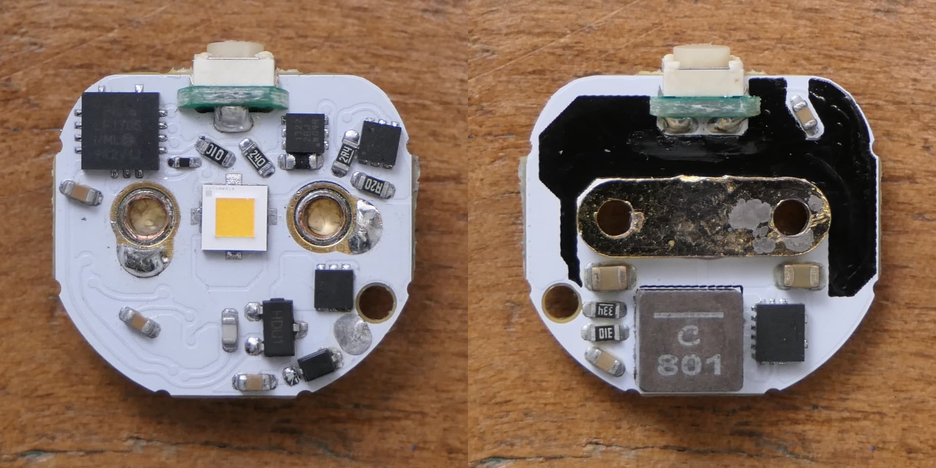
The SC65 driver uses the new TPS61288 boost converter IC from TI instead of the TPS61088 used in previous li-ion boost models (SC63/64, H/SC600 III/IV, SC700). it has lower resistance MOSFETs (6.5/8.5mΩ vs 11/13mΩ) and a 500kHz switching frequency which should allow higher peak and max current efficiency.
The inductor as been upgraded to a larger XAL5030 with lower resistance, although it’s a 0.8uH vs the 1uH XEL4020 previously used which should limit efficiency gains a bit as it’s a bit low for 500kHz.

Output and efficiency measurements :

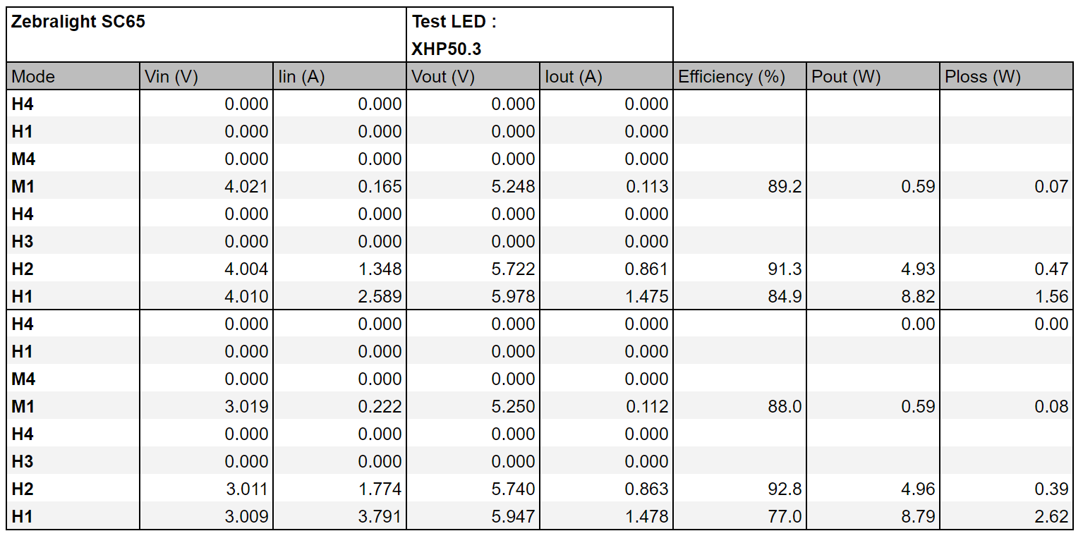
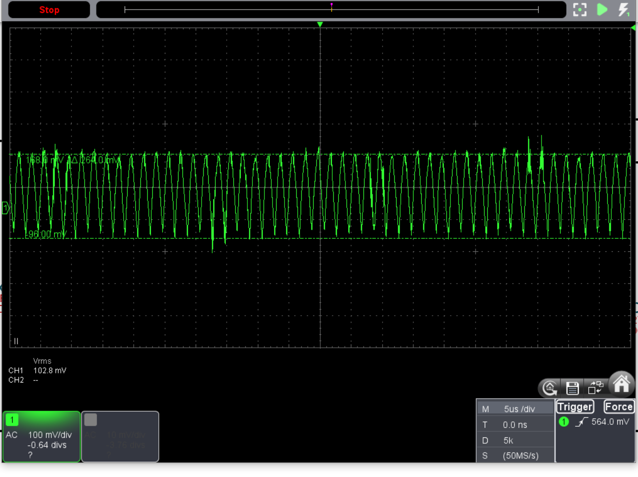
As you can see the table is incomplete, after a few measurements I noticed that the efficiency numbers are too low, so I stopped and tried to find the problem, starting with my testing setup, which I couldn’t find any problem with, then I fired up my oscilloscope to look at the output waveforms :

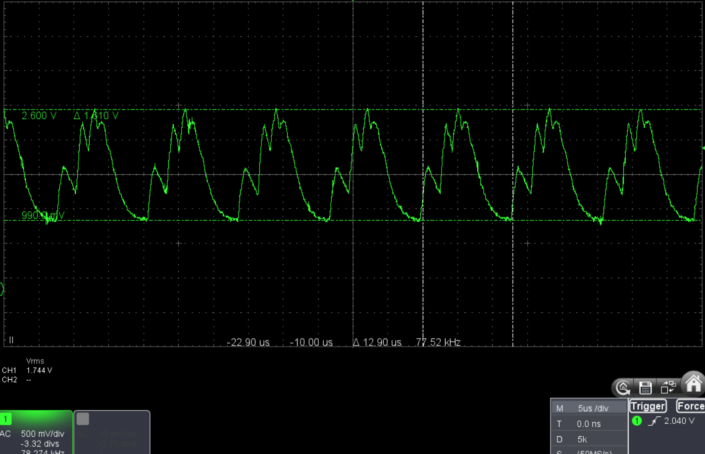
1.6V peak to peak oscillations at 77kHz at max output, oscillations that big will often tank the efficiency.
Oscillations at high output can be due to not enough input capacitance, the driver doesn’t have much, only a 10uF 0805 MLCC, plus the fact that the driver was powered with a power supply with higher impedance than a cell means that more input capacitance may be needed, but adding a bulk capacitor didn’t change anything, furthermore the problem isn’t just at high output.
Another reason could be inadequate compensation values for the boost converter, this driver uses verly little output capacitance, thus the values used in the datasheet example schematic, that are often copied directly, could be not suitable. So I looked for the compensation network on the PCB only to see that it was missing 2 of the 3 passives for it (only one cap when 2 caps and a resistor are needed), this is rather strange and as soon I saw this I knew this was the cause of the unstable output.

Fix on the driver after determining the right values :

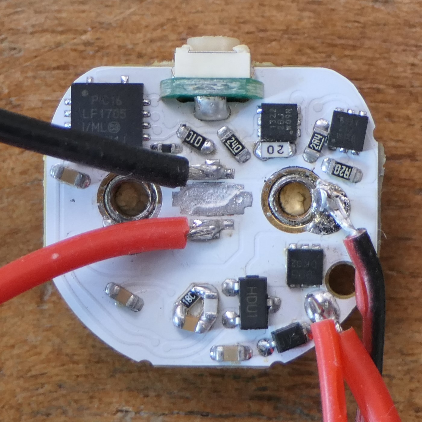
That solved the problem, 500kHz 260mV P-P ripple at max output, exactly what we should be seeing :

And the efficiency measurements.

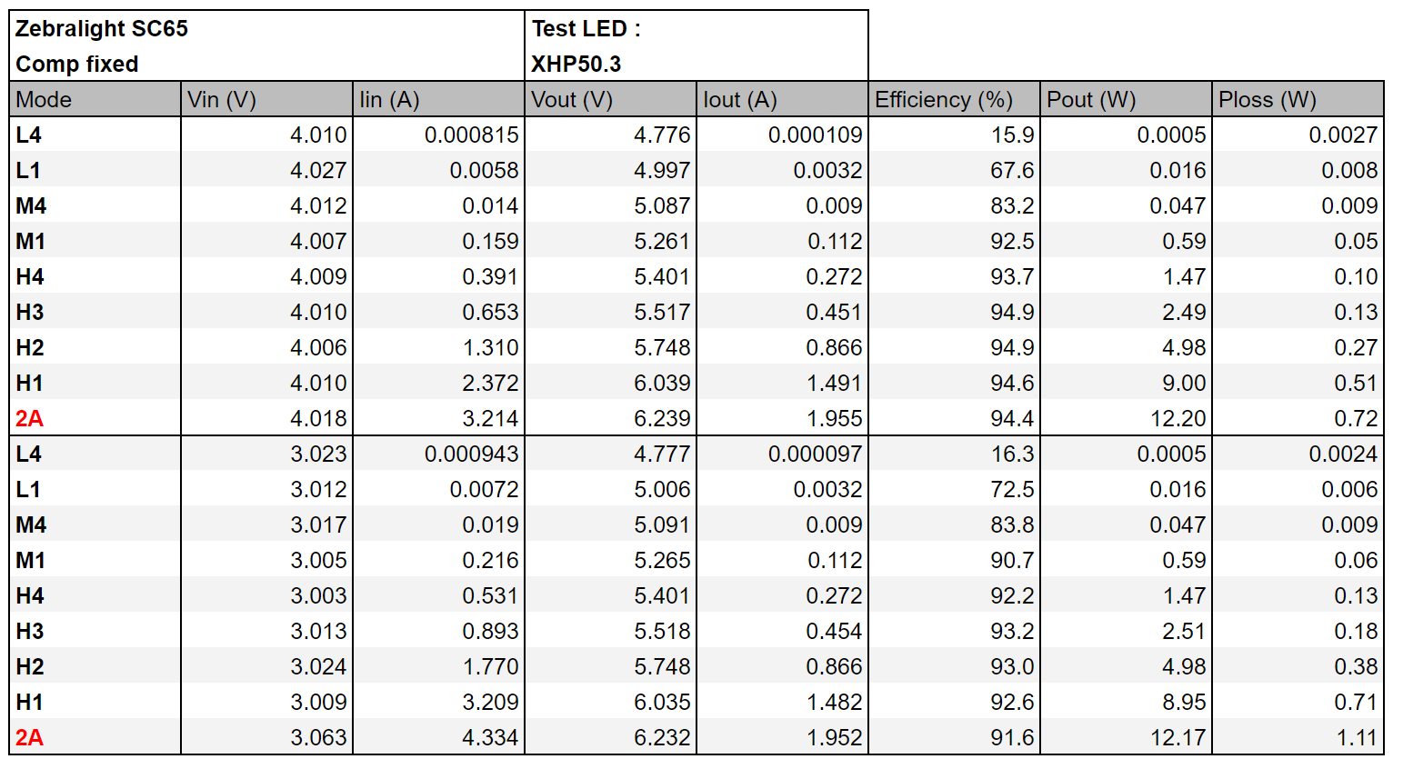
Which are more like what we should be seeing with a TPS61288 driver. Bonus 2A measurements in red.

I mentionned that the inductance of 0.8uH may be a bit low, so here are measurements with a 1.5uH inductor, I also measured 12V ouptut, for example with a LED swap to XHP35 :

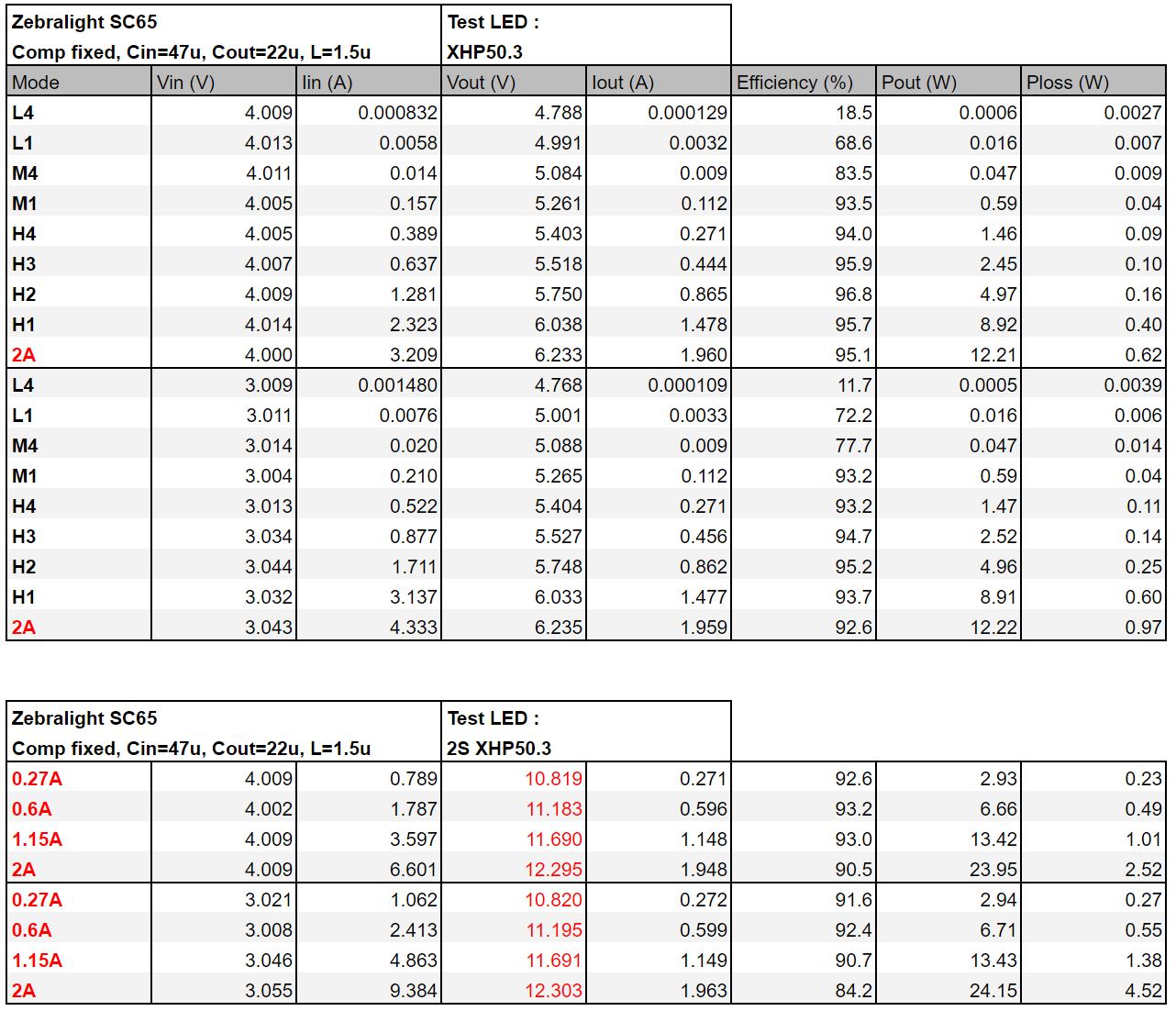
Although with a higher inductance values, the switching frequency at min output goes lower, making the flickering already present at L4 more visible.

In conclusion this is an upgrade over the previous driver used in the SC63/64, but only if the compensation network is fixed, I messaged Zebralight about this problem after testing it (26 sep, yes that’s a while ago already), they said that they where aware of this problem and that it only affected the first production batch, the next ones in 3 weeks time (that would be 17 oct) should be fixed as they “found out a better way to route the PCB”, kind of weird they went with this for the first batch though.

20 Thanks

Bravo. That’s another level . You fixed-improved Zebralight driver.

2 Thanks

Great test. It would be interesting to see are the later models truly fixed.

4 Thanks

Excellent work! Thank you!

2 Thanks

thats some truly insane work kinda sucks that zebralight is shipping defective drivers

2 Thanks

This is awesome work. Thanks. I’m curious and I didn’t see it mentioned. Why is efficiency so bad at low modes? I would’ve thought the lower the current, the higher the efficiency due to less IR2 losses if nothing else

You mentioned possibility of flickering at L4. I have sc65 dated 20Now, and I see some flickering at L1 mode.
Flashlight-Turbo-Cooled-2024-01-22-22-53-32-00-01-15-103316
Your “old” sc65 have such flickering at L1?Or is it result of improvement?)

P.s.
I probably
should emphasize that I see it at flashlight first not on graph and sc64 le don’t have such flickering.

@Bob_McBob confirmed they now ship with the compensation components added : The Official Zebralight Thread . | Page 282 | Candle Power Flashlight Forum

Thanks, my pleasure.

There are indeed conduction losses, and also switching losses that increase with the output, but some losses are fixed or mostly fixed.
For example Inductor core losses remains the same at fixed switching frequency, gate charge losses too, at each cycle the gate capacitance of the mosfets need to be charged and discharged, gate charges are very small, but these mosfets are switched at a few hundreds kHz to several MHz, it still not a lot in the end but at light loads it becomes proportionally more important.
That’s why DC-DC ICs often have a ”light load efficiency” mode, in which the switching frequency decreases at low loads (PFM), reducing those losses.
The MP34xx, often used in boost drivers have an additional mode called Ultrasonic Mode, the frequency also decreases at light load but never below 23kHz (more like 30 in practice), this prevents any audible noise from the vibrating components (inductor and MLCCs), but not going further down means that it uses more power.
In the E70, Acebeam decided to not use PFM or USM, and kept the MP3439 at full 600kHz all the time, resuslting in terrible efficiency at low modes.
Then the DC-DC ICs need a bit of power for their internals, but not much with modern ICs, in the 500nA to tens of uAs.

Aside from the power convertion part, the microcontroller will also consume a somewhat fixed power (depends mostly on Vin), it can be from a few hundreds of uA, to a few mA depending on the optimisation and control signal used (DAC or PWM).
There might be some voltage dividers on board, depending on how they are sized, they might consume a few 10s of uA.

I have two SC65 and they dont flicker on L1, at 3.2mA the switching frequency should be pretty high already, something like 3kHz if I look at Bob’s measurements. this is problably a problem unrelated to the switching frequency.

1 Thank

Thanks. That answered that question. This is a great resource. Looking forward to seeing more driver development

1 Thank

I wonder if the boost driver he has for single emitters is as good? I have a dm11 with xhp50.3. I know it’s a heck of a lot more efficient than the fet driver in my ts21. Lol. Went for an hour walk last night, mostly at 322 lumens (mode 5) with occasional turbo boosts, and I’m still at magenta so over 4.1v. And my charger stops at 4.16 so it just sips power. Checked with MM and 5000mah cell is at 4.1v

BTW “pwm” also visible on water drops at all L modes and even in M4.
L4 has low frequency flickering, too weak to measure by opple, but I think 50-100Hz.