The D3AA was just released so I thought I would give a bit of technical information about the driver used in it since I designed it.
Specifications :
- Constant current boost driver with 0.7-5.5V input voltage range, supporting low voltage AA cells and Li-ion 14500 cells.
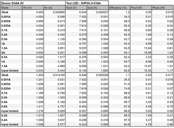
- 2A~9V output with li-ion, about 19.5W with 3x519A. ~0.6A~9V output with NiMH (Eneloop), ~5.1W.
- ~5.5A input limit.
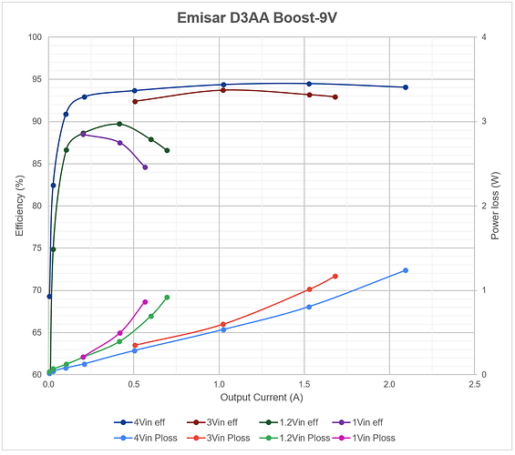
- 94%/93% peak efficiency/min efficiency at max output on Li-ion, 90%/85% on NiMH.
- 30kHz minimum switching frequency to avoid audible noise and flickering in low modes.
- High Dynamic Range : more than 100 000:1 dimming ratio.
- Electronic reverse polarity protection.
- Anduril 2 with AVR32DD20 MCU, RGB AUX, button AUX, UPDI programming with standard 3 pads flashing layout, automatic cell strength detection and then the usual Anduril stuff.
Design considerations, power and efficiency :
The design goal was to drive three 3V LEDs from low voltage AA and 3.7V li-ion (”dual fuel”) at high power. In general when doing high power DC-DC voltage conversion we want to avoid having to step up and down (buck-boost) the voltage, which would be required for a 3V output dual fuel driver, since it is inherently less efficient than either steping down (buck) or steping up (boost), both in term of energy and space required, another important issue is the rarity of high power buck-boost ICs that can work at such low input voltage.
Three LEDs can easily be aranged in series instead of parallel for a 9V nominal outout voltage, which is always greater than the input voltage, this allows the use of a boost only converter with high power capabilities and (relatively) simpler design.
Speaking about power the maximum drive current is set at 2A (or slightly above), same as the current Emisar boost 12V drivers but with one fewer LED (9V), this works out to about 19.5W with 3x519As.
In order to not completely overwhelm even the best NiMH cell, there is a hard input current limit around 5.5A, thus the maximum output current on AA is governed by this limit, which works out to approximately 0.6A output current with a good and charged NiMH cell, as the cell discharges it should do between 0.55 and 0.6A, then drop when the cell is nearly discharged.
This input limit also affects the output on Li-ion in the lower half part of the cell charge, when the input voltage reaches about 3.6V the output current will progressively decrease and reaches about 1.7A when the cell is at 3V (nearly empty).
Output and efficiency measurements :
(The test LEDs combination may seem strange, but with the additional wires and current shunts used for measurements Vout is roughly equivalent to the Vf of 3x519A in series.
Another thing to note is that power is provided with a power supply in order keep the input voltage constant, with a cell it would change depending on the mode and state of charge.
For example at 0.6Aout, a Nimh cell would drop below 1.2Vin, probably around 1.1V, but in low modes it would stay up to ~1.3V)
While the efficiency and output figures at medium to high modes are very high for a dual fuel driver, you’ll notice that the efficiency drops to quite low levels at minimum output (30uA is virtually zero i.e. the power used is barely being consumed by the LEDs).
One reason for that is the fixed MCU power consumption of about 1.6mA, this is typical for flashlights aside from ZebraLights which excel in that category.
The other reason is the Ultrasonic Mode used which keeps the minimum switching frequency of the boost converter above 30kHz, using a more efficient mode would reduce significantly the power consumption but the driver would potentially make audible noise at low modes, at very low modes it would also flicker, two things we really don’t want to happen and the power consumption cost is an acceptable compromise in my opinion. By the way this ”Ultrasonic mode” is used in many lights with boost drivers from the usual brands.
Electronic reverse polarity protection :
This is a new thing as I haven’t seen this before on a dual fuel flashlight (although I may have missed it), the common electronic RPP method doesn’t work at AA voltages so usually AA lights have physical RPP : there is an electrically neutral button/post taller than the positive contact on the driver, thus if the cell is reversed, the flat negative cell terminal touches the neutral post and can’t make a connection with the lower positive driver contact, only the cell positive button top terminal can do so, preventing reverse connection.
Consequently Physical RPP requires button top cells, which isn’t a problem at all for AA lights since AA cells are all button top, but for a dual fuel light not all 14500s are button top (personally all my quality 14500s are flat top).
I’ve been thinking for a long time on how to implement electronic RPP for low input voltage and recently I finally found a good solution. This means that both button top and flat top cells can be safely used in the D3AA.
New microcontroller :
Current gen Emisar/Noctigon lights use the Attiny1634 which can only output PWM signals, they can be used to control a direct drive MOSFET or/and they can be filtered (smoothed) into a pseudo analog voltage to control the setpoint of a constant current regulator (linear, buck, boost…etc).
The drivers that I developed use multiple sense resistors to achieve a high dynamic range, allowing low moonlight levels, changing sense resistors or ”gears” doesn’t work well when the setpoint is a filtered PWM signal so this is (partly) why I’ve been using the more modern Attiny1616 in my drivers as it features an integrated DAC (digital to analog conveter), outputting directly the desired setpoint voltage.
Other reasons include the smaller size of 3x3mm instead of 4x4mm, the factory calibrated temperature sensor and UPDI instead of ISP for flashing requiring 1+2 wires instead of 4+2 wires, again saving more precious room in small drivers.
The D3AA doesn’t use the T1616 though, but the AVR32DD20, which is somewhat its successor, the main reason the change is the better DAC both in term of resolution and lower error, unfortunately some of its characteristics are not as good as the (preliminary) datasheet promised, but still an improvement over the T1616 so we’ll take it.
Additionally it has double the ROM, 32KB vs 16KB for hypothetical space hungry Anduril features, more PWM outputs, dual voltage supply which can reduce the component count on some drivers and probably other stuff. Aside from those points it’s similar to the T1616.
And I think that’s mostly what I have to say about the hardware side of this driver, I hope that you’ll be pleased by its performances in the Emisar D3AA.
Many thanks to @ToyKeeper who implemented a lot of things in Anduril to make this possible (AVRDD, HDR, cell strength detection and various other things) and @gchart who made the initial Attiny 1-series and HDR/DAC implementation which ultimately led to this.


