The H10 flat I have is shorter than the button top H10s by quite a bit, even shorter than an Eneloop AAA or Duracell AAA.
Vapcell H10 Flat - 49.15mm
Eneloop W 2019 - 50.1mm
Duracell Optimum - 50.5mm
Vapcell H10 Top - 51.5mm
The H10 flat cannot be heavily pressed inside the host as it’s shorter than other cells.
7 Thanks
First bug report for D3AA, some people are experiencing torn O Rings at the tailcap:
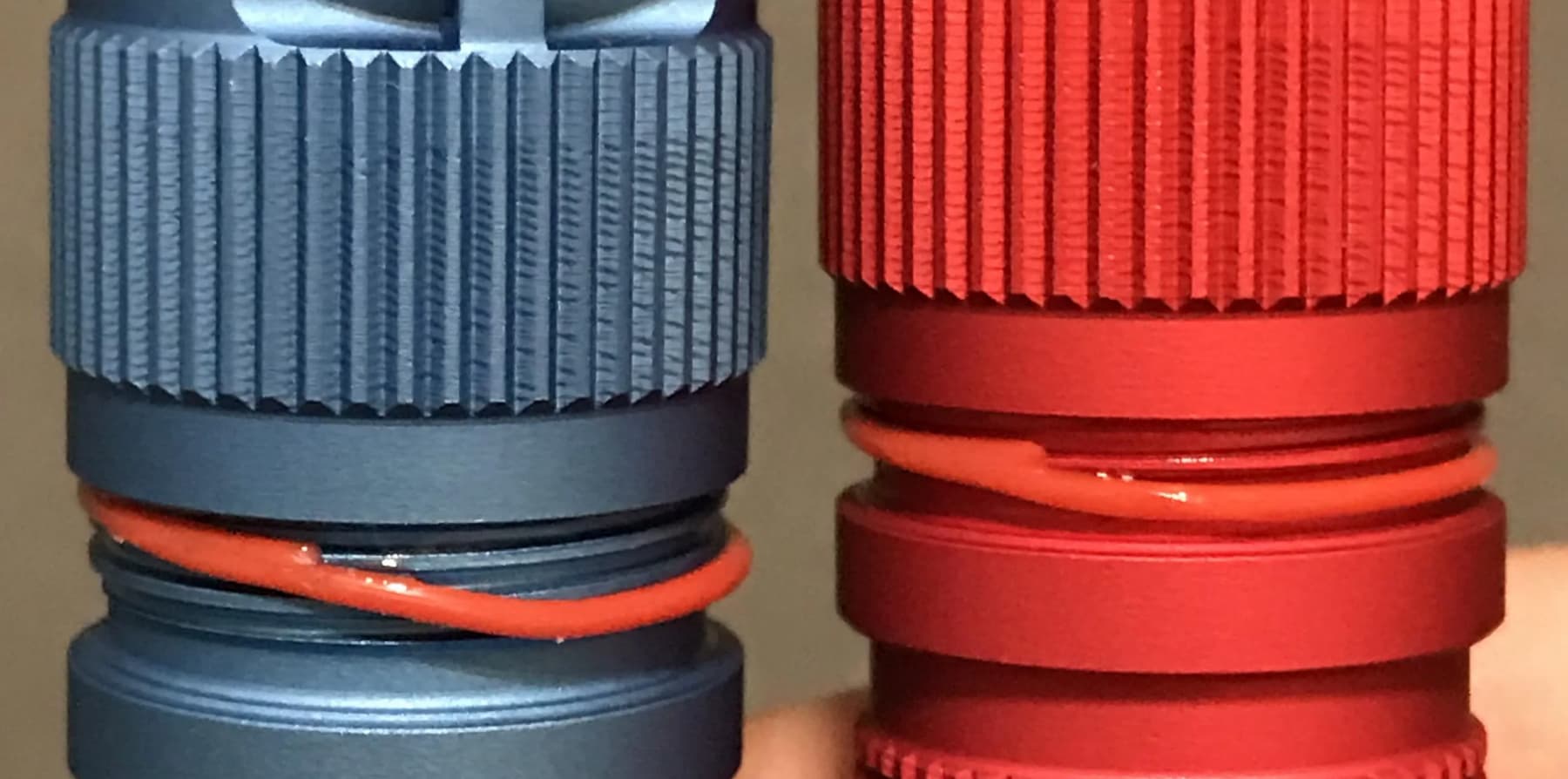
(not my photo), more details here
The issue seems to be that the O Rings are too thin and stretchy. They climb onto the the bottom threads and get cut, when removiing the tailcap.
Some people are choosing to change the battery by removing the head instead. Until a better fitting O ring solution is found.
8 Thanks
Well thats not good. Not that i would trust a Hank in water anyway… I have bad history with the ip ratings on Hank lights.
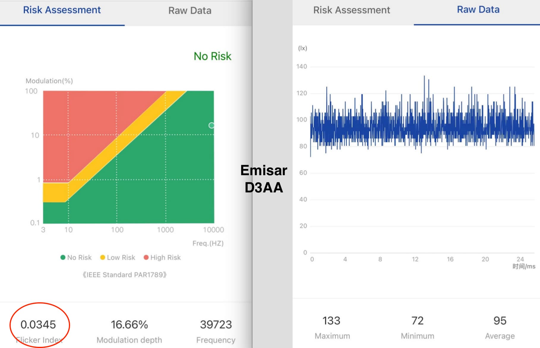
first Opple measurement I have seen for a D3AA: (not my pic)
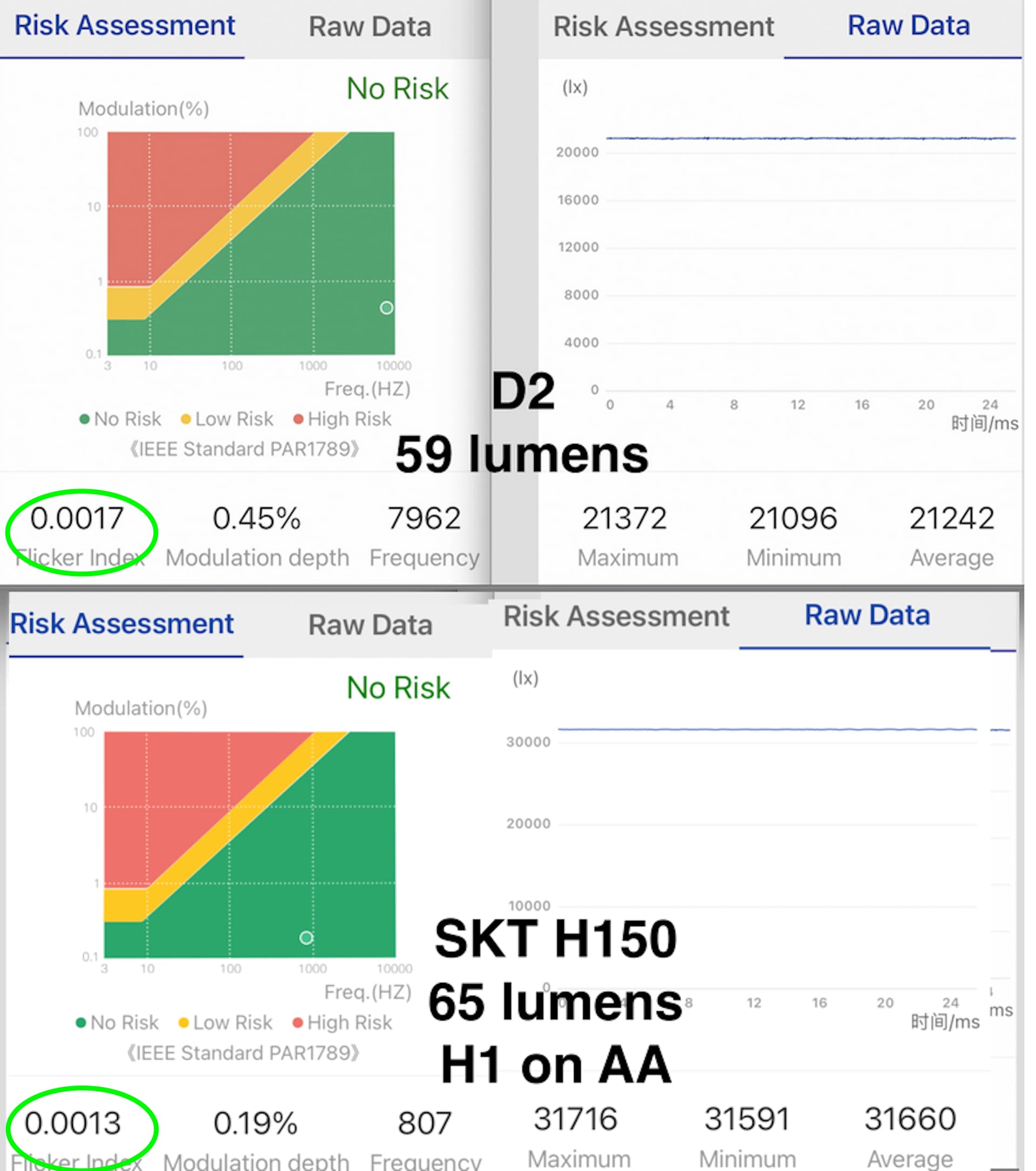
Here is the Emisar D2 on sublumen, looks similar to the D3AA which actually was at an even lower Lux:
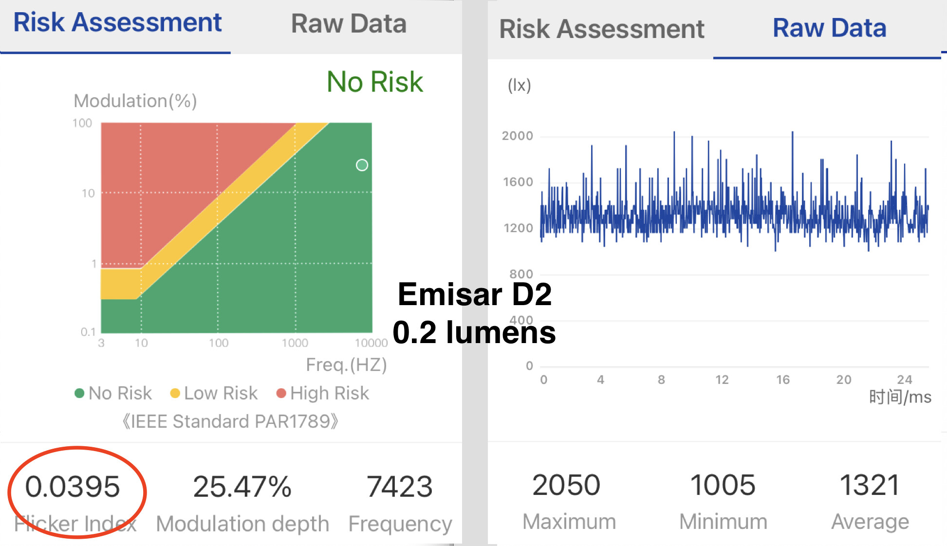
Those Flickerr Index values are at very low output.
I would like to see the D3AA at higher output, similar to my Emisar D2 and Skilhunt H150:
2 Thanks
On mine with 519A 5700K DD i get about ~
4/7 0.0025,
5/7 0.0065,
6/7 0.0082,
7/7 0.0103
2 Thanks
Thank You! I like those low Flicker Index values… exactly what I was hoping for from the new D3AA driver.
1 Thank
I’ve had the torn seals. Gone through all of them that Hank sent already. Switched to one that came extra with my Lumintop Ring King and it fit perfectly. Haven’t had a problem since.
6 Thanks
I had read that people were tearing the tail o-rings, so did two battery changes at the head and that one ripped on me. Lol . At least the tailcap o-ring is intact
4 Thanks
What boost IC does the d3aa use? I couldn’t find info about it and I couldn’t find any ICs that have low Vin(0.7v for the d3aa right?) and can drive up to 9v. Basically all of the ones that are low Vin only go up to 5.5v.
Mp3432
5 Thanks
Ahh the sweet embrace of synchronous switching power supplies /s
And do you use some kind of startup circuit? From what I see the Mp3432 has a startup voltage of 2.7v.
I damaged both the tail and head o-rings. the tail one gave out today. I dug through my boxes and spares and attempted to use the spare TS10 o-rings. Its a snug fit but it works. I think its a combination of thinly stretched o-ring and the groove not being deep enough. As a result, the ring appears to freely ride up and into the threads.
1 Thank
I agree completely
glad you found a working replacement O ring
note the TS10 O Ring is Black Nitrile, imo this is a better material, less stretchy than the Orange or Clear Silicone O rings that Emisar uses.
Plus I agree the O ring groove is directly below the last threads… a more effective design would be for the groove to have an unthreaded shoulder before the threads start.
I dont expect Emisar to redesign the hardware. I do think Replacing the Silicone with Nitrile will solve the problem
Nitrile is less stretchy and less soft, than Silicone.
Another reason to Not use Silicone O rings, is that they are less compatible with Nyogel and other lubes such as those that contain Silicone, than Black Nitrile, which is more chemically resistant to both Nyogel as well as Silicone lubes.
1 Thank
I dont know a lot about o-rings but isnt nitrile the industry standard? Why does emisar use silicone?
O-ring gland design is actually somewhat involved. The majority of flashlights use glands which do not conform to recommendations. Often times they still work perfectly fine, but other times, not so much. Non-conformant gland designs must be proved out, and general principles still apply. An o-ring “flows” within the gland. How much it flows and what it flows into must be controlled, otherwise the interface will cut or tear the o-ring.
1 Thank
Guys, this thread is supposed to be specifically about the amazing electronics that were designed for this light. Please discuss the o-ring trouble somewhere suitable.
12 Thanks
Followed this work off-n-on through the FWxA era and always wished for easy access to your efficient designs, so major props to getting this into major production! I love a low moonlight, and the D3AA has delivered on that and more.
With obvious evolutions to follow what are your thoughts on:
-
Dual channel models - couple of options, but do you have thoughts on:
a. Channel switch only - move the DAC between channels (say a headlamp with white/red, no blending needed)
b. Use PWM for a secondary channel - sigh, I’d hate to regress now…
c. 2+ DAC chips - looks like ATxmega or PICs are where they appear. Others may options?
d. Something else? -
Power saving - where is the most bang for buck savings?
a. Clock/sleep modes - looks like Toykeeper put TODOs for using the DAC in standby modes. I wonder how much power this represents? Also down-clocking in general will probably help, but I’m thinking about 2 month moonlight, heh.
b. Boost converter modes - this seems like a less plausible mod to make on existing designs, but how much do the ultrasonic modes ‘burn’ compared to lower frequency modes?
The D3AA has me thinking of a dual-fuel dream headlamp with 1xB35AM and 2xSST-20_red for a killer Anduril, dual channel headlamp (6V on each channel, but probably suitable for channel switching only).
Somebody has to have asked this already, but I got to anyways because I can’t find it…
If we never ever plan on using NiMH in these ever…can we, idk, stack some resistors and raise that limit?
Please enjoy your time here, ruddles!

2 Thanks