[ENDED] Group Buy: 46mm BLF SRK 7135 V2 - 32x 7135 Drivers - No Drama!

Thanks Tom. Yep, but not just any bar stock… Tellurium Copper. It cuts so much easier, almost as easy as brass. And yeah, tell me about it! I see piles of shavings going in the box and realize I should probably salvage it and smelt it into bullets or something, but I’m focused on the job at hand and it all goes in the scrap box with the aluminum, brass, Delrin, white nylon, polycarbonate, whatever….

FWIW… just got this bar in the other day, it’s 12” long and 1.375” in diameter. A cool $97.

Oops! Sorry, I did just get that bar in the other day, and it did cost that, but it’s the one I used to make a pill for a Raysoon F13 yesterday… for the SP-03 I had bought a piece of Tellurium Cu at 2 1/4” diameter and used the remainder of that 3” piece here.

I got an UCLp lens in for the SP-03 today, Chris custom cut it to fit, very nice of him! :slight_smile: Perfect drop-in replacement and the result is spectacular, as usual!

Some 200 lumens gained, for a total now of 3939.9 out the front.

I’m very glad I went with the Solarstorm SP-03 instead of a soup can light, this thing is very impressive! Thanks Richard! :slight_smile:

i am in for one if still possible

is it possible to get also the firmware for soem small mods /?

Sorry, but the group buy ended over a month ago. The firmware is available here.

Thanks

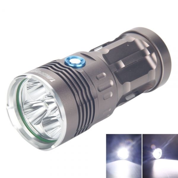
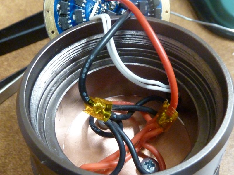
Finally finished my mod last night using this driver in a TangsPower Fing 5X, bought from TMART way back in 2014 here: https://budgetlightforum.com/t/-/26483. I'm so-so with the results of power/output, achieving "only" 14.66A measured at the tail, but with 50 7135's, should be 17.5A. Probably the bird's nest of wiring contributed to loss's. I had to use 22 AWG wires to the LED's because of reflector clearance space, then used 20 AWG off of the driver, all wires could probably use shortening as well. Here's some pics:

The 5X light:

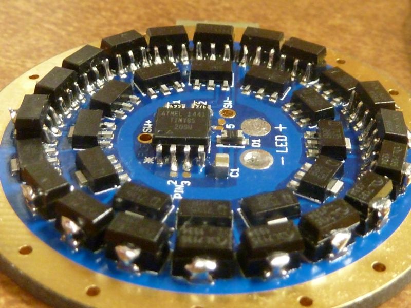
Showing the extra 18 stacked:

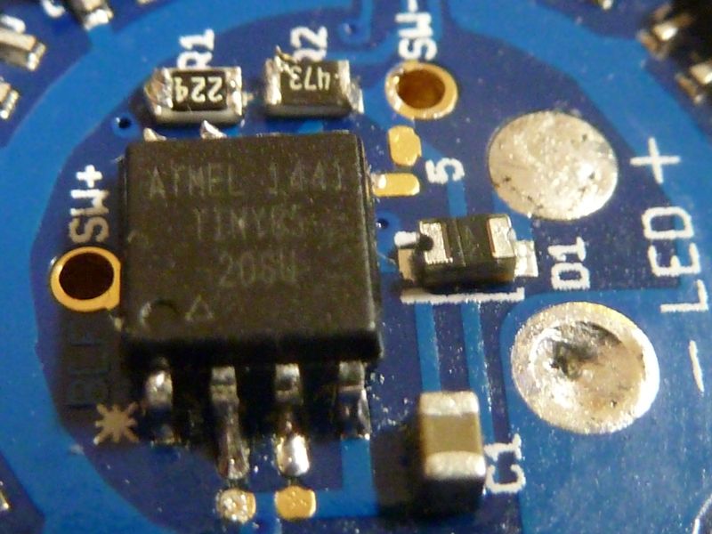
Here you can see the parts I swapped: Tiny85 for the 13A, and low drain voltage divider resistors of 220K and 47K:

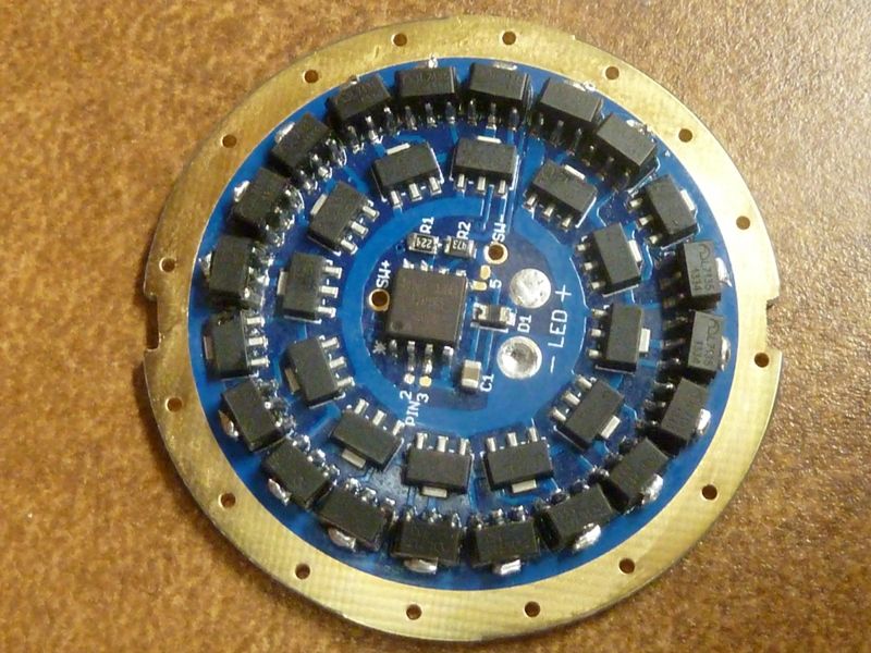
Here is the tabs sanded down, and the two notch's put in on the outer edge to help prying out the driver:

The birds' nest:

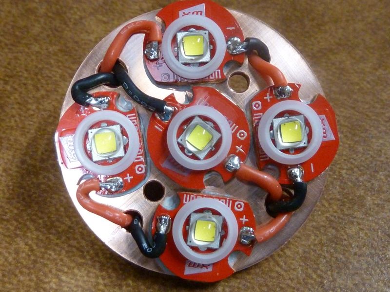
LED's mounted on the copper plate, made from 1.75" 18 gauge and 16 gauge copper copper rounds reflowed together, LED centering pieces filed down from stock size, a little:

So the good news is I didn't have to do anything to accommodate the Tiny85, like adding a cap or increasing the C1 cap. Of course w/Narsil and the voltage divider mods, the parasitic drain is extremely low, has a great lockout feature, and fully configurable modes. I found I had to raise the PWM value for moon mode to 5. 4 makes the LED's glow actually, but way too low for any use at all.

I should be getting in a UCLp in a couple days. Might just add a indicator LED using a light pipe, and see if I can reduce resistance, maybe by shortening up the wires, not sure yet.

For now, on SAM 30Q BT's @4.21v, 14.66A measured a the tail using a clamp meter (18 AWG loop built into the end cap), got:

lumens: 5134 @start, 4910 @30 secs, 41.4 kcd measured at 5m

This uses 4 U3 3D's, 1 U4 1C in the center. The UCLp should bump it about 5% or so.

Cool mod

Love the soldering Tom. You do amazing work in more ways than one.

Awesome work there, Tom!

Thanks! I’m very curious though on the loss’s of amps though, so may do some more testing/mods.

14.66A is 2.93A per LED, 3.665A per cell, and getting bout 1,000 lumens per LED, seems little low for U3/U4’s. At 2.9A per LED, Vf should be fairly low for fresh cells.

The stock driver is 31 x 0.380, so 11.78A, plus 18 * 0.350 is actually 18.18A. Could be the wiring, but maybe also something in the ground path.

^ what they said. Very nice soldering on the stacks, nice work with the firmware.

You might consider stars for a mod like this, the star configuration stacks together nicely and allows for the use of larger mcpcbs. :wink: Lead pads are also usually in a better configuration. Still, looks like you’re getting really close to the desired result, sucks that the 22ga leads had to be used up top, 20’s would be nice, perhaps a 20ga Teflon lead coming off the emitters? The 20ga Teflon is usually even slimmer than 22ga Silicone. Then you could use 20 or 18ga inside the pill to deliver to the short through-shelf of the Teflons.

Yea, was considering teflon, but they are sooo stiff. If I reflowed the Noctigons down, then teflon would have been a good choice. I got Teflon in all common sizes now.

Think'n bout reflowing MCPCB's on lights like this, seriously thought if I could set the solder paste under the MCPCB's, then use dabs of thermal epoxy on the edges of the MCPCB's, then lock the positions in with the reflector and centering pieces in, tightening up the reflector screws (I replaced the stock ones with better, longer ones already). Once the epoxy hardens, dis-assemble the reflector, remove the centering pieces, then torch heat below the plate to set the MCPCB's solder paste. I think the epoxy would not make a mess, or burn or something. The copper plate is actually two rounds reflowed together to get the desired thickness, so might risk they will come apart and sliding, unless maybe setting the screws in place to keep them aligned.

Dunno if that would work well, just might. Think if I torch heated the plate with the reflector and centering pieces in, the centering pieces would probably melt.

What actually worked out well with this "Fing" light was there was a lower, slightly narrow shelf lip/edge in the housing, so I could use that with using a thicker copper plate. If I had to work at the same height of the stock big 5 LED MCPCB, would have had to use something very thin, or in 2 stages in diameter, if you know what I mean. Again, without the luxury of being able to machine things out.

Just can't imagine doing a 7, 8, or 10 LED SRK light like this... Wiring alone would be insane.

Bypass the wiring. Seriously.

Arrange the mcpcb’s so that you can access the common pad and cut a thin sheet of copper to fit over matching pads, then run a single wire up through the shelf to attach to the sheet. It’s thinner, carries ample current, and produces a neat result while maintaining the current flow we desire. :wink:

Think I need a visual , but kind of/sort of think what you mean. Did you ever do something like this before? Definitely hard to visual this, and maybe can be done in multiple segments, not just one '+' template and one '-' template, if I understand this.

I’ve done it with quads in a small light, works like a charm. And yes, you could do a couple of groups if it made it easier to work pos plate around neg. It prevents having excessive wires everywhere and allows a single fat lead for each pole coming up through the shelf. These can come in together or on opposite sides, whatever works.

Hhmm - might work. Certainly lot less wires, then possibly improve voltage drops. I re-wired the tail PCB jumpers using 20 AWG Teflon, and replaced the 18 AWG loop with 16 AWG, but didn’t get any gains.

Crap somehow i missed this GB.

Maybe it’s time to scrutinize all the added chips? You’re missing enough amperage to account for 8 chips, what are the odds it could be that many giving issue? The cells should do it, fairly easily, so it’s either a loss through the wiring or some chips are not activating or both.

I don't think that this driver is a great one to stack chips on unless you've got a ton of voltage overhead, like with red LEDs or something like that. I think that the traces are just too thin to do much more than 32x 7135 in a normal setup without a ton of resistive losses.

Ah, well see? There ya go!