Formula for hotspot angle in a reflector

Sure! My first attempt defines the hotspot as “a region that captures all of the light hitting the reflector and has a constant intensity equal to the maximum intensity of the light”. Of course, this is a very crude definition and does not account for the presence of the corona, or the fact that the hostpot is not quite constant in intensity.

My derivation in this topic defines the hotspot as the region where the entire rim of the reflector appears to be lit. From my observation of various flashlights (walking to the target and looking into the reflector), this definition captures exactly what part of the beam I would classify as hotspot.

I would argue that the non-monotonicity is indication that the formula is doing something right!

For a perfectly Lambertian source, and ignoring truncation at the base of the reflector, the intensity of the beam depends on the reflector only via the diameter, not on height. Thus, as long as the diameter is fixed, the maximum intensity achieved stays the same.

Now consider what happens to a reflector if you fix the diameter and let height range from 0 to infinity. At height 0, the portion of light captured (p) equals 0. At height infinity, p = 1. Thus, p can be thought of as a “rescaled” version of reflector height.

Now, fixing constant the diameter (and thus intensity, and thus cd/lm, and thus acuity), consider what happens to hotspot angle as height increase from 0 to infinity:

  • At height close to 0, the reflector captures only a tiny amount of light, but still must achieve the maximal hotspot intensity. Thus, the hotspot must be small.
  • At height close to infinity, the reflector captures almost all of the light, but the spill angle becomes very narrow due to the elongation. Since the hotspot cannot be wider than the spill, the hotspot is also forced to be very small.

At this point, we have established that:

  • At height close to 0 (thus p close to 0), the hotspot angle approaches 0.
  • At height close to infinity (thus p close to 1), the hotspot angle approaches 0.

So however the constant in front of 1/Acuity depends on p, the dependence f(p) must satisfy f(0) = 0 and f(1) = 0. If the claim f(p) = sqrt(p(1-p)) has any chance of being correct, it must satisfy the above boundary conditions.

The problem of generalizing these calculations to other optical systems is interesting. For LEPs, it’s unclear whether the emitter can be modeled by a Lambertian at all. For convex lenses like Z1, the roles of hotspot and spill are exchanged, and there is no corona. I’m happy to do the analogous calculations later today, which I expect to be way simpler than for a reflector.

I would argue that the resemblance among the different models is an essential feature of the physical system we try to model, and in no way a miracle or coincidence!

I agree that the full/diametrical divergence angle is most useful for most folks. They may also prefer using degrees over radians, which is a bit unfortunate: radians are the natural units to work with mathematically, but degrees normalize commonly encountered angles into the natural interval [1,10].

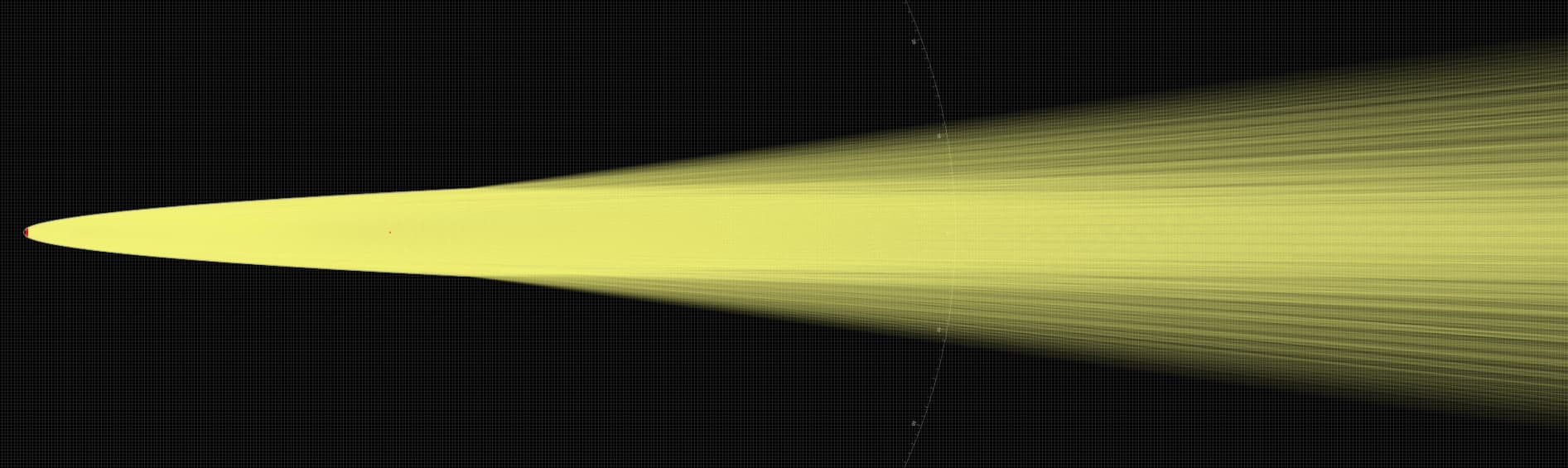
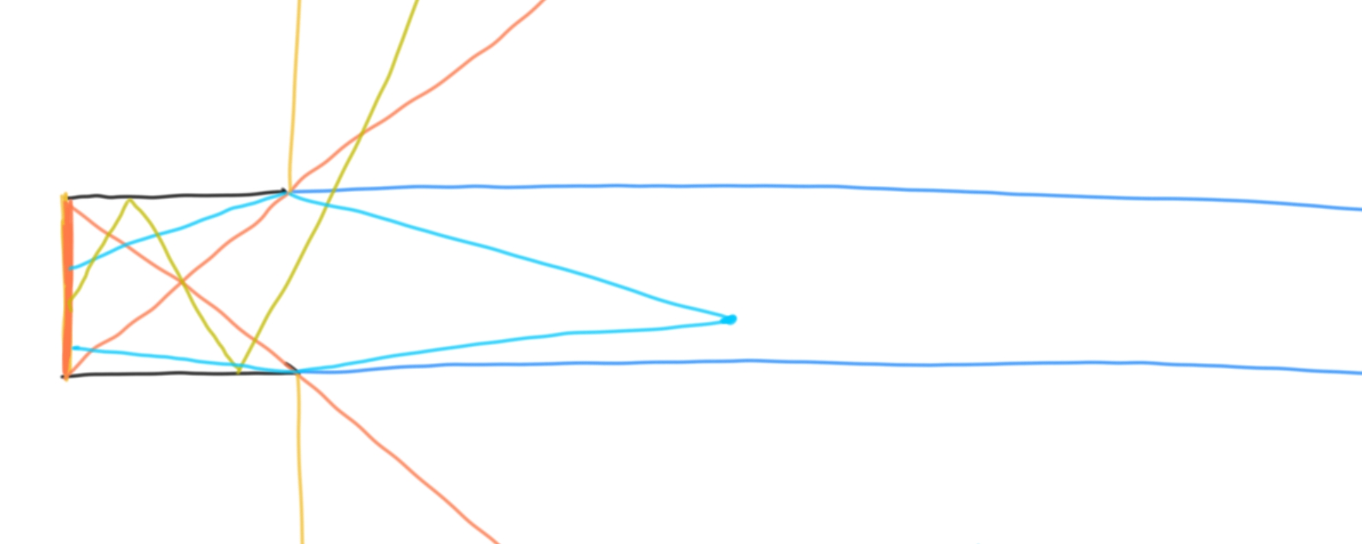
On a tangential note: I think my ray-tracing method can give you an explicit formula (though not necessarily closed-form) for the entire angular distribution of the beam. The computation may be long, but I’ll do it if you’re interested! Once I do it, I hope that it correctly predicts the separation of the beam into hotspot, corona, and spill.

The gods or etendue may interfere before that could happen :⁠-⁠). The beam angle can’t be smaller than 2d/D, I think.

With very elongated reflectors, there will be a phase change in beam behavior.

With the existing reflectors that we are familiar with, a photon out of the emitter gets reflected 0 or 1 times before exiting the reflector. With a very elongated reflector as described above, this number can increase to 2 or more, and at very oblique angles, resulting in a “super-spill” that is wider than even the classical spill, which is defined as light that hits the reflector 0 times.

As a result, an arbitrarily narrow spill and hotspot is compatible with conservation of etendue.

Could you clarify what the variables are?

It’s a fun thought exercise, but I really think you’re both overthinking it too much…the thing is, I believe you’ve both mentioned (or inadvertently alluded) that the function of hotspot to reflector is some constant PROPORTION, but you’re still trying to treat it as some absolute value.

Evidence of overthinking is when LEP are mentioned…lensing and basic optics (focal length/distance, image projection) have already been explored/implemented ad nauseum…

As for @QReciprocity42 's mention of hotspot must be small depending on reflector heights, we can clarify that the hotspot being the overlapping rays isn’t necessarily a full circle, it could end up being a ring of sorts. I.e., for a near infinitely short reflector, then the hotspot would approach some PROPORTION of a near infinitely thin ring. I believe that your definition of “hotspot” is apt, as long as the reader realizes this.

Could you describe/clarify what exactly you mean by this? I am unable to translate this into a mathematical statement and thus am unable to agree/disagree. It might be helpful if you make reference to the list of parameters introduced in the first post, so that we know precisely what you’re talking about.

Same as above.

While I agree with the latter part, I believe it is worth it to independently perform the computation just to ensure that we have an essentially correct understanding of how light behaves.

1 Thank

I have to add, if a near planar reflector were used, surface area would equal infinity at infinitely thin, so technically the entire beam would be hotspot besides the outer infinitely thin corona.

It is not specified what variables are held constant. If height is held constant, then a near planar reflector would have a large surface area but still let through a lot of spill.

If diameter is held constant, then a near planar reflector would have a small surface area approaching that of a disk with equal diameter.

1 Thank

These are all indicative of proportions.

Not equal, but proportionately equal. A hotspot, by definition, contains spill, and only exists because a portion of the spill is redirected and forced to overlap on other spill.

**added
It’s useful to conceptualize what would happen at infinity, so an infinitely wide but thin reflector reflects almost all light at almost every given angle except at what we can call the horizon. The corona becomes super thin, and the hotspot is essentially 99.99999999— % of the spill.

An infinitely tall but narrow reflector would yield an imperfect inverse..ignoring focal pints at the moment, at the exit aperture, it would form an infinitely thin donut hole, and some graded hotspot that make up the entirety of what we would misconstrue as the corona, when in fact the corona would be that dimmer “donut hole”, and the hotspot would be the rest of the graded “area”.

I agree that the variables introduced are proportions in some sense, but it does not clarify your original statement that

For example: hotspot and reflector are not variables/parameters, so it does not make sense to say “function of hotspot to reflector”.

This is either ambiguous or untrue–could you draw a picture to clarify?

In a classical (non-recoil) reflector, a very wide and thin reflector results in only a tiny proportion of the emission hitting the reflector, so one can expect the hotspot to be close to 0% of the total output.

1 Thank

Ah you’re right, apologies. It forms a giant donut/ring, i was totally errant in imagining a slightly elevated recoil focal point for some reason.

1 Thank

There is (or are) some proportion that the functions of a reflector derive to the hotspot, I tend to stutter when I’m excited. Please treat my blathering as the textual form of stuttering.

1 Thank

I see! In optics textbooks, concave mirrors are recoil reflectors, so it’s sensible to subconsciously take it as the default.

That’s relatable. I’m equally excited to see what ideas you come up with!

1 Thank

I’m more a conceptualizer these days, my gift with numbers has since faded a while ago…you could rattle off a list of theorems and proofs to me and even explain the rationale, and most of it would go right over my head, lol. But if you tell me something like “big bowl throw much light forward if bowl tall and wide”, I’ll have some tiny inclination of what you mean.

In any case, further ruminating on the concept of reflector shapes, if we purely take the beam profiles immediately upon exiting the aperture of the reflectors, it is logically impossible not to have some kind of donut hole because there will be some region of the reflector curve that doesn’t exist, i.e the center…then, we look at the convergence/divergence of the beams, and for the smoothest reflectors, assuming perfect curves and machining, and there should always be a donut hole or clover up to a certain focal distance…back to the maglite analogy, the reflector never changes, but the angles do because the light source changes positioning.

And for me, that’s too much conceptualizing for one day, my brain is fried.

D is the rim diameter and d is the LED diameter.

I’m afraid not quite.

Here is a decent read on why etendue matters. It’s similar to entropy in thermodynamics, and also probably similarly tricky and counterintuitive to apply.
etendue_wood.pdf (301.3 KB)

Etendue of a lambertian source like what we assume for LED is π×A_source.

Whatever you do with this light in a flashlight (reflector or otherwise) it will produce some ‘beam+spill’ output (doesn’t matter how you call it) from now larger area. This places a hard lower limit on the beam divergence angle, even if you pack this light into uniform cone - any other pattern can make divergence angle only greater. This limit seems to be for the full output beam angle = 2√(A_small/A_big).

So going back to k/Acuity, I think that the shape of the function you concocted for k may not be possible.

This has been a great read, but 2 items remain unaddressed:

(1) According to the article itself, the conservation of etendue can be violated if the system is allowed to be lossy. When calculating the hotspot of a reflector, any light that doesn’t end up in the hotspot is considered lost, so the conservation of etendue–as stated–does not need to hold.

The gobo is presented in columns 2-3, page 19 as a counterexample: a beam can be narrowed arbitrarily just by shading/blocking.

Furthermore, the description of etendue given in the article is merely a gist of the idea, not its true definition. It’s analogous to saying that “the area of a shape is base times height”, which certainly holds for rectangles but is not a working definition for all shapes.

“if we are talking about a light source, then the two factors that we multiply together to produce etendue are the area of the light emitter and the solid angle of the light beam. (These are simplified descriptions, but I think they get the point across.) etendue, sometimes called throughput, is the product of these two measurements”

(2): The below heuristic is not making sense; could you state things more precisely?

Even if we assume conservation of etendue, having larger reflecting area makes a beam narrower, so you cannot get a lower bound for divergence angle this way.

If you believe it is not possible, do your best to prove it, or to show where my derivation breaks!

The onus is on you - extraordinary claims require extraordinary evidence! It sounds like Russell’s teapot…

But seriously, you won’t be able to narrow the beam pass this limit if all the light from the source ends up in front of flashlight, which it does for reflectors. This is isn’t my idea.

To cheer you up - many have tried before you :⁠-⁠)

See post #1 of this topic for the derivation–I have done my part concerning “evidence”. Now the onus is on you to demonstrate impossibility, if you believe so! Feel free to ask if any part of the derivation is unclear or difficult to follow, I’ll do my best to explain.

This claim remains unjustified by a working, rigorous argument. Recall that my claim is that the hotspot and spill can be made arbitrarily narrow, not that the entire beam can be. Also recall:

The below simulation fails to show reflections of order 2 or more (thus the super-spill), but I hope it gives a clear picture of why the spill angle is essentially bounded above by the angle at the emitter subtended by a diameter of the reflector opening. Interestingly enough, it seems to display a corona (defined as region of space where you can see some part of the reflector lit up) that is wider than the spill cone. Though not surprising, if one grabs a ruler to back-trace where the outer rim of the corona is coming from.

:⁠-⁠) Sure. And I’m also sure there are plenty of detailed proofs in optical literature since etendue conservation law is some 200 years old and worked ever since, but here is the gist of it.

If:

L is luminance
A is emitting area
Ω is solid angle
Flux = 1 lm
d is source diameter
D is output diameter
L_led is constant (lambertian)

etendue conservation implies:

L_out ≤ L_led

Since L_led = 1/(A_led×π) and L_out = 1/(A_out×Ω_out), the Ω_out can’t be smaller than π×A_led/A_out

This minimum solid angle translates to planar full cone angle lower limit of 2d/D (small angles, but it will also work without this approximation, it’s just more messy expression).

It works for any passive optical system, including reflectors.

So, for the part I’m interested in which is what to use for k in k/acuity, I don’t think the semicircle as above is possible.

BTW I’m impressed by the logic and discipline of your derivation, it’s just the expression for k won’t do despite well-intentioned thought experiments to support to.

Thank you for the more detailed exposition of etendue conservation. I still don’t believe that my formula violates it at all, but have come to realize that there are 2 potential misunderstandings in our discussion:

  1. The formula being proposed is for the angle of the hotspot, not the entire beam, and not even all of the light that hits the reflector–some of that ends up as corona. So applying conservation of etendue for the light that hits the reflector, i.e., hotspot + corona, does not disprove a formula for the hotspot alone.
  2. It is conceivable that we are working with different definitions of the same term. To be more precise than before, I will try to give rigorous definitions, plus examples, for the following terms. You may feel free to disagree with my definitions, as long as you provide yours.
  • Hotspot: region in space where, for an observer located there, the entire rim of the reflector is visible and lit by reflection of the LED.
  • Corona: region in space where there exists some point of the reflector that is visible and lit.
  • Spill: region in space where there exists some point on the LED that is directly visible.

By the above definitions, the hotspot is always a subset of the spill: if you can see the entire rim of the reflector at all, you are within the tangent cone of that rim, which always contains the emitter. Trivially, the hotspot is also always a subset of the corona. It does not necessarily always hold that the corona is a subset of the spill: sometimes the spill can be narrower.

To give a simple and illustrative example, consider a cylindrical reflector, with the emitter consisting of the entire base of the cylinder.

Orange vertical segment is emitter, black is reflector.

  • The hotspot is the infinite solid cylinder enclosed by the blue lines. A cyan-colored “witness point” is shown to be inside the hotspot, via the two light paths from the reflector’s rim. In this setup, the hotspot has zero divergence angle, and in the limit (for a far enough observer), consists of 0% of the emission.
  • The spill is the cone enclosed by the orange rays: in this cone, you can always see some part of the emitter directly.
  • The corona is the entire half-plane to the right of the reflector’s opening. There’s a dark yellow-green ray in this region that gets reflected twice before exiting; nevertheless, the observer far out in the ray would see the ray’s last point of incidence on the reflector as lit. Note that in this case, the corona is wider than the spill.

That said, I do not claim that my original formula works for extreme setups like this: estimates such as small-angle approximations (which stem from the assumption of a small emitter) were used freely without a quantitative error bound.