It doesn’t matter how you radially divide the light in the Ω_out. Etendue conservation sets the lowest possible limit on the Ω_out (which is when the intensity is radially uniform). In any other case it’s larger.
I’m not quite sure which statement of mine you wish to disprove, but your above explanation for conservation of etendue seems to rely on conservation of total luminous flux, which is not the case going from the bare emitter to the hotspot.
Without conservation of total flux, a simple gobo/pinhole would disprove the claimed conservation of etendue, as your article remarks.
Maybe this will help: for reflectors as you increase h/d, you’re in effect shifting more light into the beam, i.e. subtracting it from the spill, while the spill gets tighter. You’re not losing anything. Thus you can’t make the beam tighter than its hard limit as above.
I’m not trying to disprove anything. It’s just that your half circle expression for k = f(p) does not comply with this limit.
This doesn’t actually help, sadly, because you are making an argument for the tightness of the entire reflected beam (hotspot and corona), while I am only claiming a formula for the hotspot, which is a small fraction of the light collected by the reflector. So we are talking about completely different things. In particular, the following claim is false for my definition of hotspot:
This distinction has already been made before; please read it carefully:
These two sentences do not seem consistent with each other. Furthermore, I find it strange to claim that my formula for the hotspot angle is impossible without ever referring to my definition of what hotspot is. I gave precise definitions of terms for the sole purpose of avoiding ambiguity and making sure we are on the same page, so please indulge me.
Let’s not invoke etendue conservation limit for the tightest achievable beam.
If beam angle can be expressed as k/acuity and you fix h/D at some value, say 1, there must exist a value of k that results in the correct beam angle - regardless of how you define the beam boundary or what the radial intensity distribution within this boundary may be.
Now, increase h/D by increasing h and leaving D alone. The beam angle won’t change as it is defined by d/D which has not changed.
If you use the previous k value, k/acuity will compute beam angle value that is too small (increasing h/D increases beam intensity, which in turn increases acuity in the denominator). To counteract it and bring beam angle to its correct value, k must increase.
If you decrease h, the opposite happens and k needs to decrease.
This does not depend on the choice of the initial value of h/D, which implies that whatever shape k(h/D) function may have it must be strictly increasing - a property that half circles don’t have.
It seems that you are more interested in modeling the beam angle than the hotspot angle, the latter being the subject of this thread. It may be sensible for you to create a new thread to talk just about beam angle. Which one do you want to talk about: beam angle or hotspot angle?
So far so good, I think this holds for both beam angle and hotspot angle.
Lost me there a bit. Why does the beam angle depend on only d/D? And before that: could you give a precise definition for “beam angle”?
What is the justification behind this claim? Is the increase in intensity bounded, or does it become arbitrarily large if h is allowed to be arbitrarily large?
Could you shine your light model on an imaginary far-field wall so that the wall receives all the light from your model. Could you then sketch what you will see on the wall including all the zones and their transitions the way you see it and annotate them as you wish. Could you also sketch how you believe the illumination will vary as you move from the centre to the outer edge of what you see.
Give me a list of parameters as defined in post #1, and I’m happy to make a sketch to help you understand my model and definitions of terms. The definitions, along with an illustration, are presented in the following post.
Also, I hope to find some time tomorrow to compute an explicit formula for angular intensity, in 2 dimensions. Perhaps a plot of that would be a better illustration than a hand sketch. This time I will try to either avoid approximations, or give explicit error bounds.
Let’s concretely define what the hotspot is. In my opinion, a hotspot is any region where redundant light is applied due to the optics or reflector. HOWEVER, there needs to be some standardized metric that designates how much of an increase in relative intensity constitutes a hotspot.
For example, I keep bringing up maglites because of their focusing feature. Are we assuming optimal focus in terms of a centralized hotspot relative to the rest of the beam? Are we referencing the ring that forms because of suboptimal focus? To get a baseline, we must establish a baseline…is it the “mule” bare source model? Or are we starting with a near 0 height reflector?
**added
Another question arises when we bring up spotlights. Are the hotspots partially a result of the proportions of the reflector to the light source, and the proportion of height/width/curve? If so, a perfectly scaled down handheld (source, source depth, reflector, focus) SHOULD produce a proportionately scaled beam.
Lambertian models cannot apply to many LED. Their phospher/light layer isn’t domed, and most of the domes aren’t uniformly projecting in all viewable directions. Sorry if that has been covered already.
1 Thank
It’s good that now we are finally addressing the issue of formally defining the terms we use. I proposed a definition in this post because I find this definition to be (1) aligned with what I visually observe, and (2) mathematically easy to work with. But I do not claim this to be the only sensible definition, and am glad to see proposals of alternative definitions.
This is a very good start. The first sentence does not make the distinction between hotspot and corona, but the threshold proposed by the second sentence may solve this problem.
1 Thank
Apparency is often the enemy of truth/actuality, lol…we need to try and cover as many non-ideal bases as possible after establishing what the ideal might be…
**added
I.e., by natural/observational definition, a corona would be a “crown”, or a circlet ring. However in terms of spill and beam profiling, a corona should be classified as some region where the intensity is above the baseline, but is not intense enough to be “hotspot”. Take an out of focus donut hole, for example. The donut hole, by apparent definition, is “hotspot”, and the bright ring would be the “corona”. However, both mathematically and scientifically, the hotspot is the bright ring, and the donut hole would either be spill or corona.
Hotspot, corona, and spill (if that accounts for all the light the flashlight emits in your model), but not in terms of what an observer may or may not see but how it looks whan you illuminate a far-field wall. Can you also sketch what you believe is the relative illumination profile going from the centre to the outmost edge of of your model’s projection (I imagine the edge of spill).
First: yes, in my model, the union of hotspot, corona, and spill account for 100% of the light that comes out of the front.
It is sensible to define things by the observer because they are, in a sense, dual to the emitter. If you observe a very bright spot on a wall, it means that an observer on that part of the wall would receive a lot of light, equivalently, see a large portion of the reflector lit up. If you observe no light on some part of the wall, it means that an observer there does not receive any light from the flashlight, and would not see any part of the light lit up.
I decided to define the regions by observer because the observer has access to more information than the person holding the light. Both parties have access to how much illuminance is emitted in any direction (i.e., how much of the reflector lights up); however, the observer has additional information in seeing what part of the reflector lights up, and what doesn’t.
This information allows for a definition of beam parts that depends solely on the geometry within the reflector–which is specified by a short list of parameters–rather than the beam projected on the wall, which we have no formula to describe. A sketch will be incoming shortly.
1 Thank
For all intents and purposes, this makes alot of sense to me, as I’m more mechanically minded. You don’t study **terminal ballistics based on the launch, but based instead on the termination and affected area.
1 Thank
Here’s a sketch, but perhaps something more interesting arises from this request.
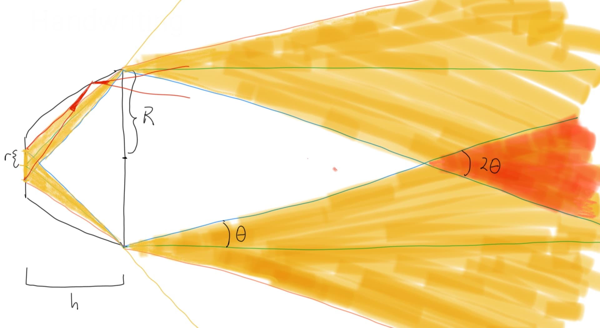
The hotspot is in orange, and the cone traced out by a pair of thin yellow lines forms the spill. Corona is much trickier to visualize without overcrowding the diagram with ray traces.
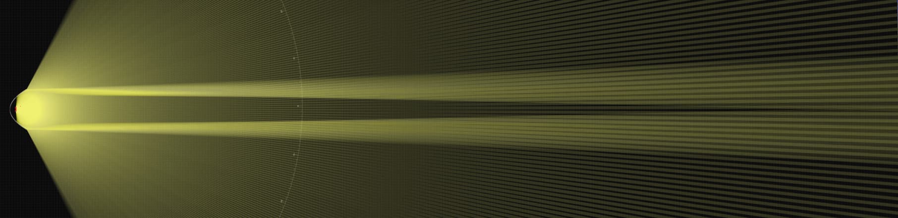
But more interestingly, a simulation suggests an alternate definition of the hotspot!
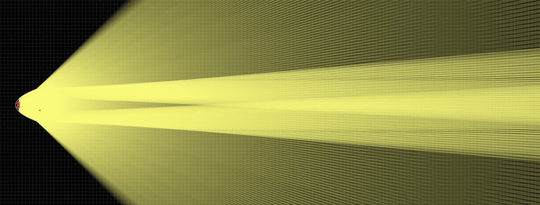

I should have tried this earlier, as the simulation has much better accuracy than the crappy C8 reflector I’m stuck with. The sketched partition suggests the following alternative definition:
- Hotspot (2D): the region in space where an observer can see both halves of the reflector lit at some point.
This definition admits a natural extension in 3D, by restricting to the plane that contains the observer and the axis of the reflector. This definition gives a hotspot that is wider than my previous definition, but I expect not by much. If there is interest, I will start a new thread and redo the calculations with this new definition.
I am slightly troubled by this new definition because some heuristics suggest that the difference between hotspot and corona angles is the second-order error term of a small-angle approximation and thus should be much smaller than the hotspot itself, which is not what I observe IRL, but I’m not sure until I sit down and do the math. I might trust the math more than I do the image formed by an imperfect reflector in the real world…
1 Thank
Realized that I somehow missed this post, my apologies.
Regarding your first paragraph, I think it comes to down to different folks preferring to approach a problem in different ways. Some folks (often associated with algebraists) enjoy general theories/ideas, while some other folks (often associated with analysts) enjoy getting their hands dirty sorting out the details. I am very much of the latter type.
The “donut hole at close range” phenomenon you pointed out, due to truncation of the reflector by its focal plane, is observed both irl and in the simulation from the post above!
1 Thank
Could you simulate a less practical reflector, such as one where the height is half the width, like those old cobalt headlamps used to use?
Spill would be the muled portion of light, corona would be anything that is of higher intensity than the spill, up to the point of the hotspot where the intensity would be the highest. Again, that would require some established baseline as to the proportions of the beam lol…
Another definition for “hotspot” would be “where the regions sit distinctly proudest **of the aggregate.”
For example, in knurling, technically the outermost (most intense) protrusions are hotspots, but specifically only those that protrude significantly more than the average. If there were a spike or spikes in the knurling, for example, that were substantially more intense and were noticeable, those would be hot spots.
Of course! I believe lots of the old lamps are a combination of normal + recoil reflector, since the emitting source emits backwards as well as forwards. Like an incandescent maglite. I’ve simulated a very shallow normal reflector, very deep normal reflector, plus a recoil.
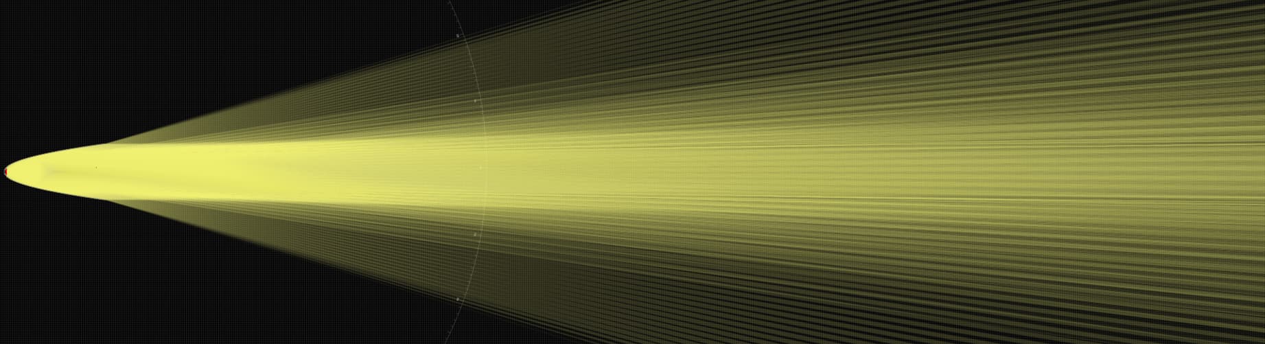

- Shallow reflector: picks up only a tiny proportion of the emission, and hotspot takes a long time to converge, due to the large truncation.
- Deep reflector: the hotspot/corona appears to become harder to define–there appears to be some phase change in beam behavior past a certain depth.
- Recoil: no spill, and exhibits behavior similar to a deep normal reflector.
Regarding the deep reflector, I think I have a guess for what the critical threshold is.
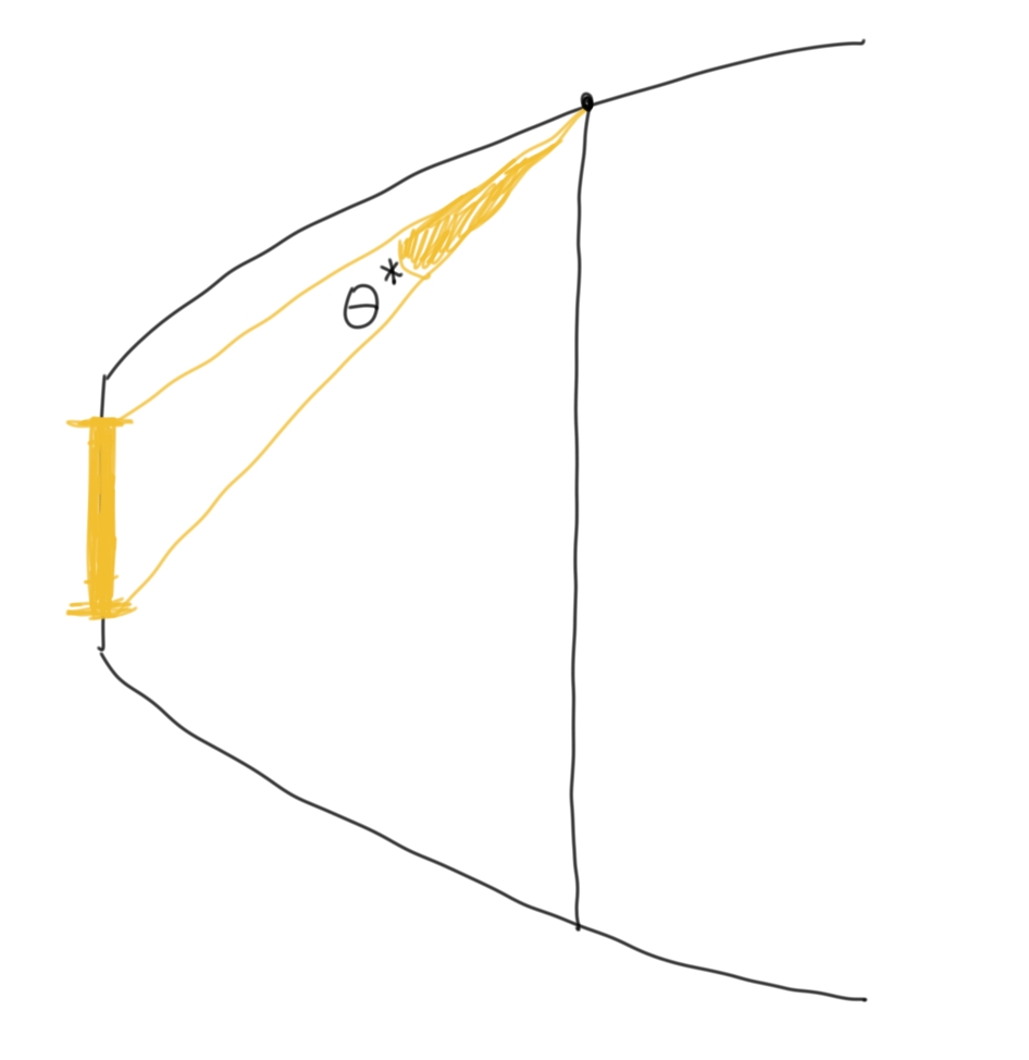
Imagine the emitter (yellow segment) inside an infinite parabola. Every point on the parabola sees the emitter as having some angular size θ; furthermore, there exists some point on the parabola where that angle is maximized. I think that is the threshold. If a reflector is shallower than this point, everything is easy to handle. If a reflector is deeper than this point, one might get a compound hotspot…but I’ll try to find out exactly where this critical threshold is.
My goal tomorrow is to compute explicitly an angular intensity plot, which would allow us to test what definitions for hotspot/corona might be reasonable. It will be posted in a separate topic.
1 Thank