This is my first entry in my How-To series. These are step-by-step instructions for tasks related to flashlight modding. There are many different ways to do things, so I will show the methods I use that work for me.
This How-To will show how I add AMC7135 current regulator chips to a flashlight driver board. Our desire to do this is to increase the output current to the emitter. J)
This isn't really a soldering how-to, so I assume that the reader already has basic soldering knowledge and skills. There are many soldering tutorials on here and the rest of the internet.
Parts, tools, and supplies required:
- 7135 based linear driver
- one or more extra 7135 chips
- soldering iron
- helping hands
- tweezers
- magnifying loupe
- solder
- solder wick, for any solder related boo-boos
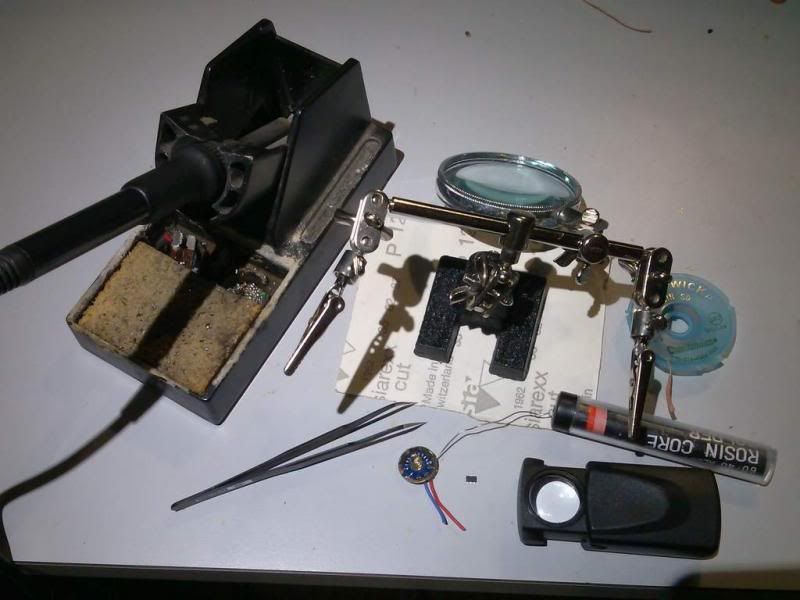
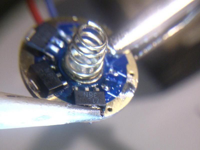
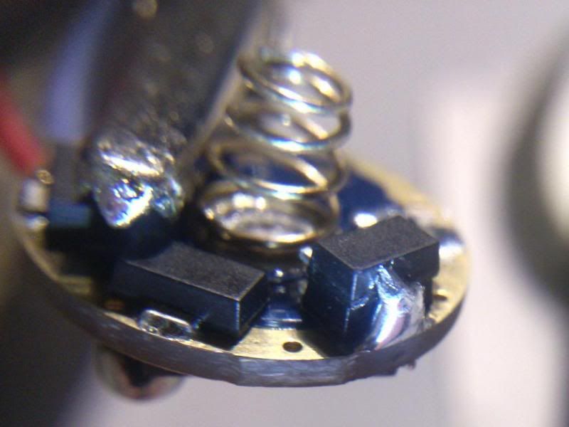
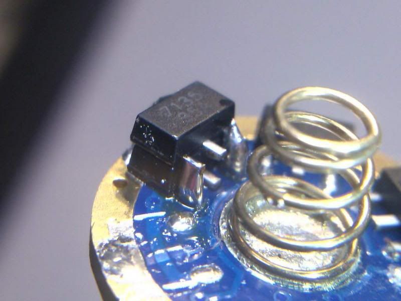
Here is a close-up of the parts. I had this driver kicking around. This is a generic version of the NANJG and it's not good. I harvested it for parts, but it's good enough for this How-To.

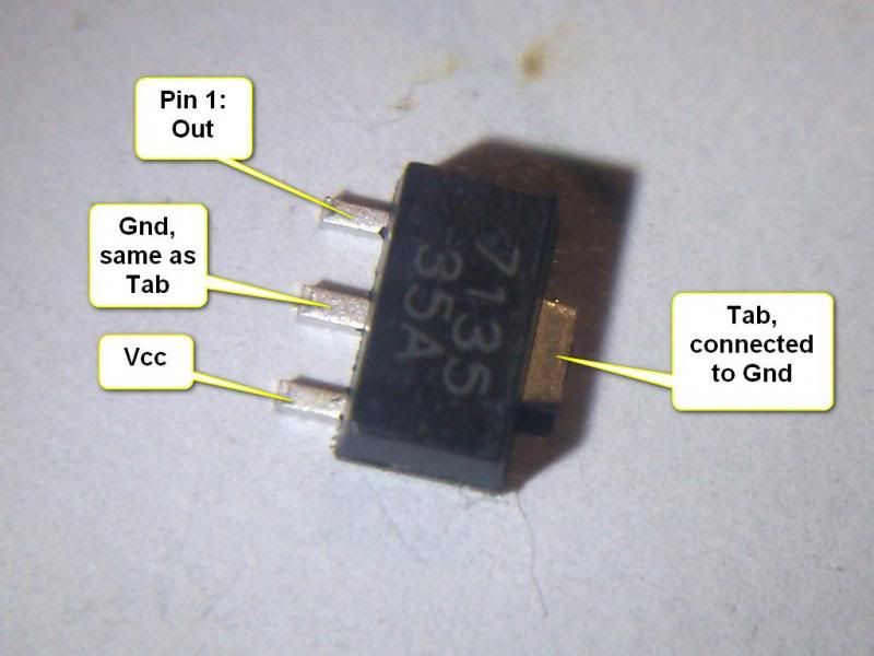
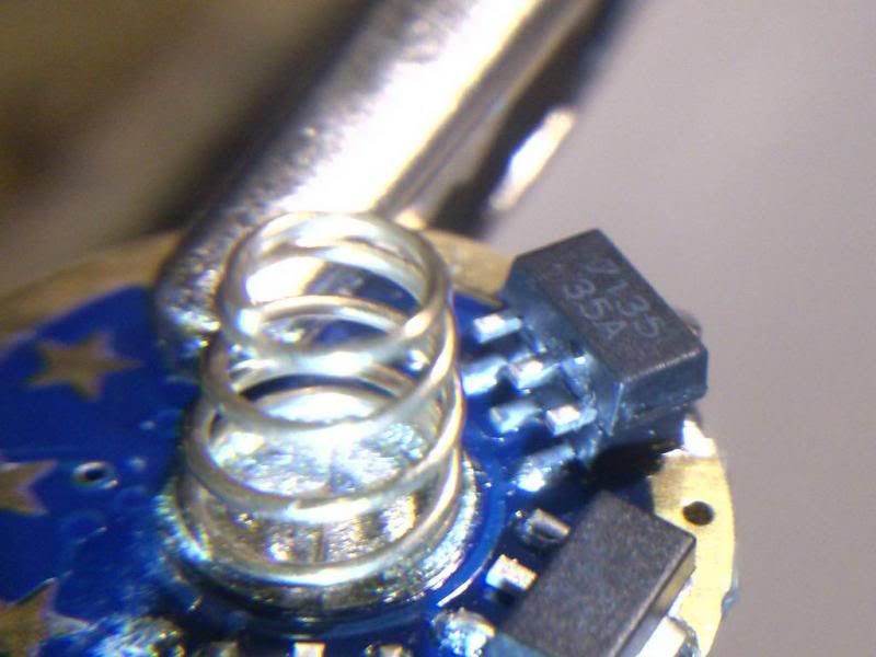
The 7135 chip has three pins and a tab.
Pin 1 is 'Out', where the cathode (negative) side of the LED is connected
Pin 2 is 'Gnd', which is connected to the tab, which will make things a little easier for us later
Pin 3 is Vcc, power for the chip itself. Without power, it blocks all emitter current flow. This is the pin that the driver controller (MCU) uses to control the output power.
Tab is 'Gnd', connected to Pin 2. The tab is the main thermal extraction path for the chip, so it is important for it to be connected to something to pull heat away.
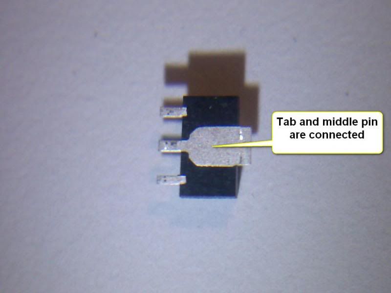
On the bottom side, we can see how the tab and Pin 2 are connected:
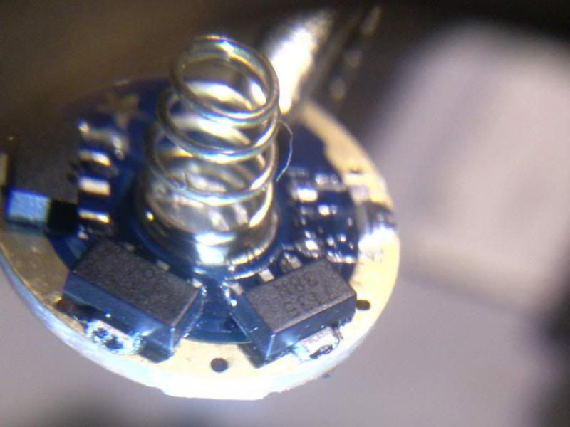
Start by placing the driver in the helping hands. I'm adding a chip on top of the one on the right.
I start by re-tinning the tab, pin 1, and pin 3. This tends to make the process a littler smoother when making the first solder bridge.
Tinning makes freshens up the solder so it accepts new solder easier.
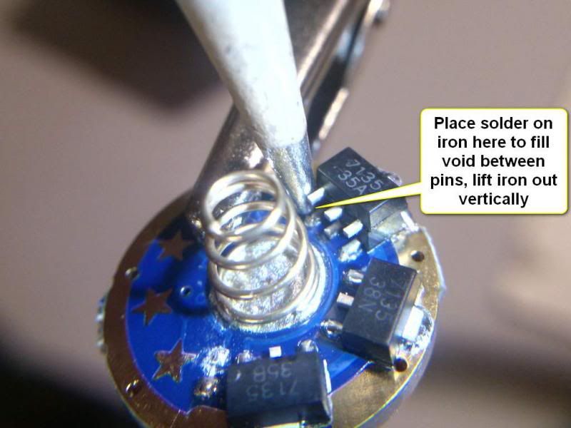
Prepare your iron by loading up a healthy portion of solder. Estimate enough to fill the void between the two tabs of the chips, maybe a little extra. After the first couple of tries, estimating the amount is easier.
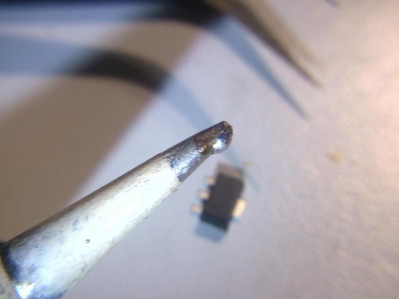
Using tweezers, hold the new chip directly over the existing chip.
Use the soldering iron to apply the blob of solder into the space between the tabs. Raise the soldering iron vertically to get the solder to move upward to the top chip. You may need to take a few swipes in order to get it to stick. Add some solder if it looks like there isn't enough. Once it bridges align the chip before removing the iron. Once aligned, remove the iron, wait for the solder to solidify, and the chip will stay in place.
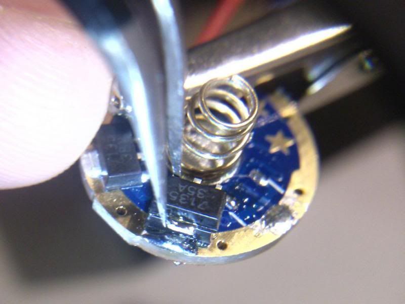
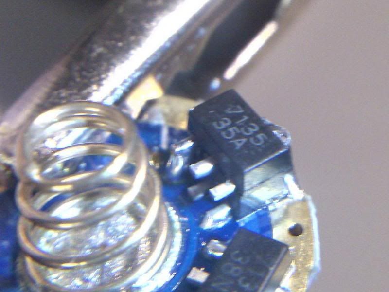
Now we move to the pins:
I hold the soldering iron vertically whenever possible. This helps because we can extract the iron vertically. Plase the tip of your solder right in between the two pins so it contacts the iron. Melt enough to fill the gap, but too much could results in unwanted shorting to nearby pins or components.
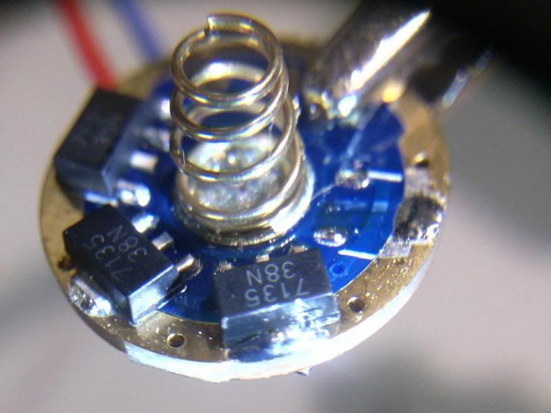
There, the first one is done:
Now repeat for the other side. And, we're done! There's no need to solder the middle pin since the tab is connected to it.
Like any soldering task, there is some practice required. You may not get it right the first few tries. Just keep trying and you'll get it. Do it enough and it becomes second nature.
Pretty soon you'll be building your very own 40 chip 7135 driver ;)

Happy Modding and thanks for reading! searchID8936

