Kinfire K1200s - less words - more pics

Hey Guys!

I got a Kinfire K1200S from gearbest for a Review…

at first: some data from their website:

Emitter Type: XM-L L2
Total Emitter: 12
Lumens: 8700
Battery Quantity: 6 x 18650 (Not included)
Mode: 5 (High > Mid > Low > Strobe > SOS)
Focus: No
Rechargeable: No
Waterproof: IPX-6 Standard Waterproof

It came in a “Courui” Box (togehter with the Olight i3s i reviewed earlier)
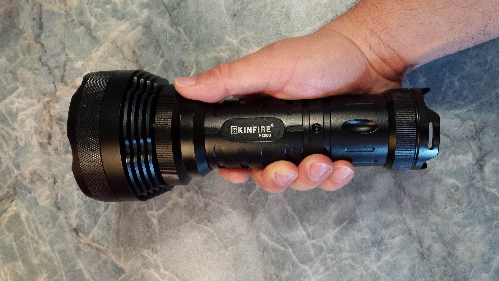
a BIG Light!

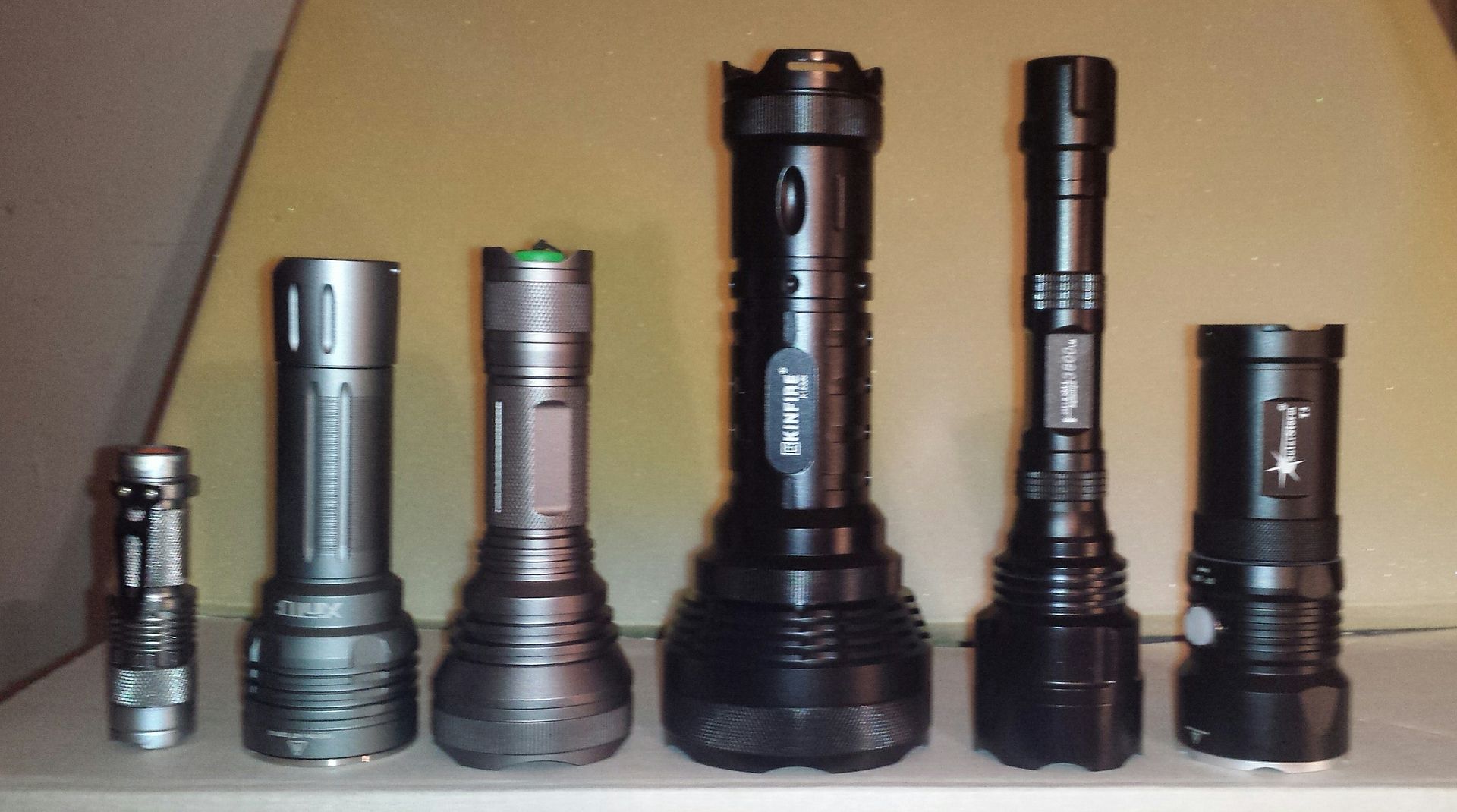
a SK68 - XinTD X3 - HD2010 - K1200s - Skyray 3xT6 - Solarstorm T3

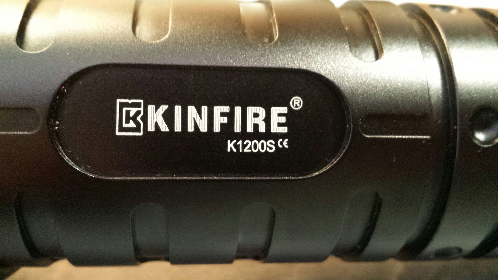
the laserengraving is well done, the anodisation is okay - but on the slippery side

tailstand is possible!

did i say its big?

the tailcap hast 3 recesses and 3 holes for lanyards

“tactical”grip is possible - kind of

looking at the front end you see 12 Cree XM-L2 sitting in small reflectors

the lens doesnt seem to be AR coated, but its very clear!

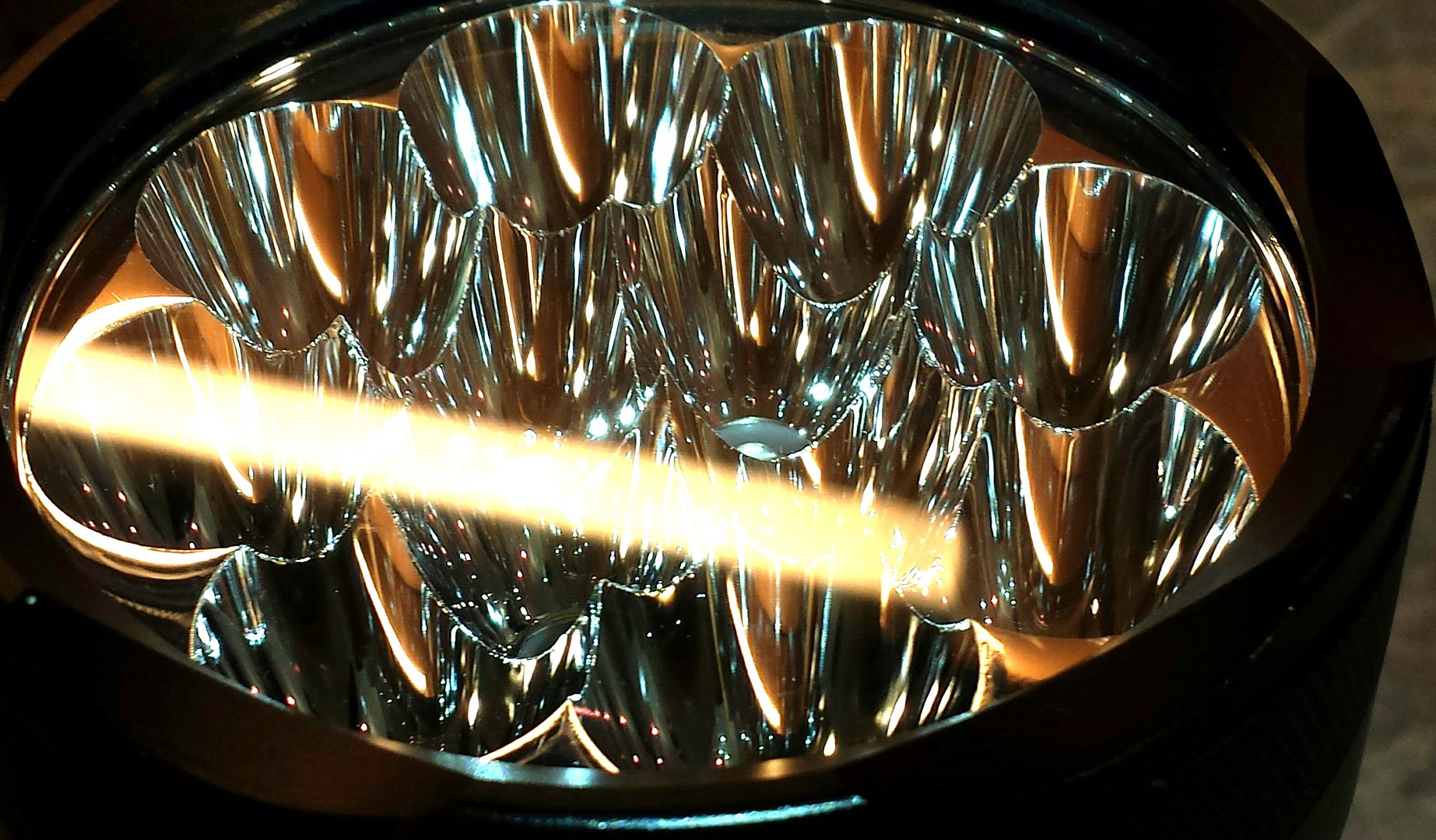
the emitters are well centered (mostly)

the bezel is not glued - but not reased also (neither are any other threads)

the backside of the reflector is flat

the “head” is not very massive - so i think heat coulb be a problem

emitters are wired 2S3P - in 2 channels -> 12 in total

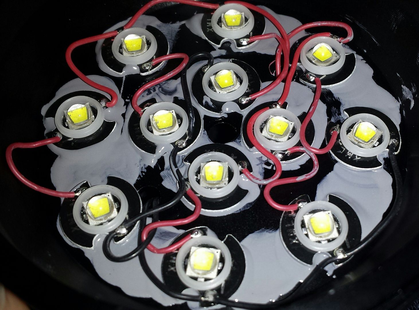
i tink you can see how thin the base is…

lots of thermal grease is used

the centering rings are very small

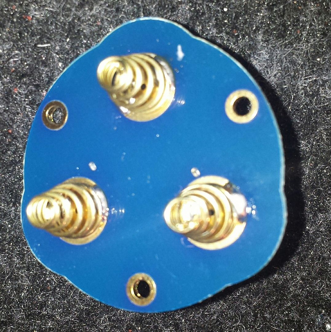
on the back side of the head you see a plastic retaining ring and a quite massive contactplate made from brass to prevent the cells scratching the driver (i like that!)

uuhm - not soo massive - but does the job well

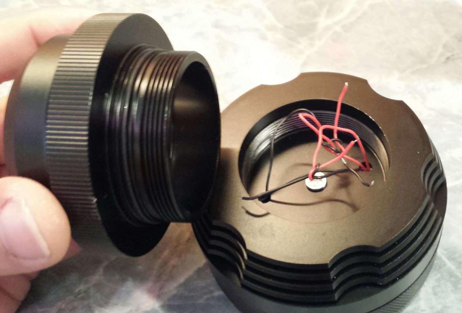
batteryside of the driver

veery thin wires :frowning:

the “shoulder” (aka driver compartment) is easyli removeable - some times it opens before the batterytube…

all in a row

the driver - a HX-1337a

aah - there is the second one :wink:

the battery tube is very massive and blank on the drivers side to make good contact

batteries are 2S3P

the tailcap side is anodized everywhere

the rubber cap of the switch is exchangeable

the switch

at last - a beamshot…
left is the reviewed light - right is the older XM-L version i got earlier

both lights on low (shows PWM - which i can hear, but dont see it irl)

maybe i got a warmer tint?

that would explain why the L2 Version i got is not much brighter than the L Version…

short conclusion:

a nice light – but for me a little bit too big

if i can pump up the Lumens – it will be okay (never believe the “China Lumens” !)

overall a good light, but i think forr 100 bucks there are better ones.

but stay tuned for the modding!

Nice thread. Been wondering what these guys look like inside ever since RaceR86 published his "Retard" mod.

So the emitters are wired 2S3P in 2 banks driven by separate buck drivers. I wonder why the use buck drivers in these arrangements. Gives a bunch of options for modding. How much distance you estimate exists between the top of the inductor coils and the bottom of the emitter shelf?

Thank you for all the great info (Picture worth a thousand words) M4DM4X. :)

EDIT: Edited question for clarity.

9mm Sir :wink:

what driver-modding-tips would you suggest?

-> i am already heat-thinking :slight_smile:

With no side switch, I wouldn't pay more than around $45. A tail clicky only on a light that big is a fatal flaw.

Wow, I don’t have much interest in this high of count quad-emitters but the battery setup is awesome, I’m thinking I’ll be getting one of these to use as a host for a multi-MT-G2 monster, just have to find some (3-4) individual reflectors that can be opened up to fit MT’s and are short enough to fit the head.

Could you give us the reflector height?

I guess if I stayed with the stock driver (Verses going with a DD FET type driver like RaceR86 did), I would do the following:

  • Pull the stock MCU and air wire in an Attiny13a (Loaded with my favorite FW). You would want to feed the PWM the Pin closest to the "4" on your two buck converters (They appear to be labeled LEDA "1304" in the pics).
  • Stack another R010 on top of the 2 Voltage Sense Resistors to see what happens to current. I have a feeling you could probably safely short the banks as they are already pretty close to zero (.01 ohms).

Can't tell what FET's are on your board right now.

I don’t know what we know about this driver… but it looks like it has a space for a current sense (?) and the 4 little tabs may be mode selections (?).

The tab’s are most likely just pad’s for an unneeded component, doubtfully they do anything with the modes.

The sense resistors are the R010 ones (one at 6:30 in your quoted pic, the other under the 9 o’clock toroid).

more driver pics:

i want to paint the R010 with conductive laquer :wink:
easier than soldering :smiley:

height of the reflector: 19,8 mm
outer diameter: 79mm

€dith says:
i am thinking to make a giveaway for the XM-L Version i was sent in the first place… :wink:

Nice review :slight_smile:

i am not sure…

just putting copper between base and driver

or

active cooling? >)

Conductive paint may be conductive but it's probably not as conductive as the 0.01 ohm resistor you want to bypass. Use wire.

okay - thanks!

i think beefing up the springs and rewiring to the LEDs is necessary anyway…

IF i want to dedome some for more “throw” - which are the choosen ones?

Maybe those pads are for a connector… meaning there is likely a function that comes out of those 4 pads; one being ground of course.
Assuming the large pads are just to hold the housing and are not terminated

A stock retard light.. :D

Ok, its not retarded when stock.

IMO, I dont think gearbest got a lot of "review" by sending you this light. This was basically just a teardown with a few thoughts. Sorry, but I expected to get to know how the stock light performed when seeing a review of it.

Well documented teardown though. Looking forward to the mod, and hearing a bit about the stock driver.

In case anyone is interested in some silly bright stuff, here is my mod thread on the retard light (same host). Beamshot comparison here.

Thanks for the pics & reviews!

well RaceR86 - you are right…

more words:

the light is of medium build quality when it comes to details…
dry threads (squeaking a lot!)
since i have two of them: the diameter of the threads differ - not all parts fit on both Hosts

ano is well done
no scratches on the light or lens

using only the tailswitch is not easy with one hand!

UI:
HI - MID - LOW - STROBE - SOS
NO mode memory - after 5 secs it starts again in HIGH
the switch is a forward clicky - press half to cycle to the level you need and press full (klick) to stay there

not words, but numbers (from my HS1010A)

ceiling bounce “Lumen”
table(table#posts).
|K1200s|45|160|390||||
|K40M|0|5|91|219|360|560|
|Solarstorm T3|8|107|213||||
|Olight R20|0|96|||||

K1200s Amps over the switch
table(table#posts).
|0,4|1,4|3,5|

Lux @ 3m
table(table#posts).
|K1200s|320|1200|3000||||
|K40M mod.|2|105|1455|34500|57000|86000|
|Olight R20|190|1020|||||

Looks like low 2000’s lumen-wise. Hmmph. Definitely needs to be modded. :slight_smile:

i “only” bridged the sense resistors…

ceiling bounce “Lumen”
table(table#posts).
|K1200s|45|160|390||||
|K1200s +|63|230|570||||
|K40M|0|5|91|219|360|560|
|Solarstorm T3|8|107|213||||
|Olight R20|0|96|||||

K1200s Amps over the switch
table(table#posts).
|0,4|1,4|3,5|
|0,75|2,66|6,8|

Lux @ 3m (actual reading)
table(table#posts).
|K1200s|320|1200|3000||||
|K1200s +|400|1600|3800||||
|K40M mod.|2|105|1455|34500|57000|86000|
|Olight R20|190|1020|||||

numbers quite fast falling due to heat i guess…
values above taken after 5 secs (where at first “flash” about 10% higher)

next: thermal management, braiding the tailswitch, thicker wires to the LEDs

Wait a sec - the reflector has to clamp down all those stars with only one little off-center stud?