LED test / review - Fireflylite FFL350RD (3500 K 96 CRI) - good beam, rectangular classic LED chip but with round cut-out!

LED test / review EN


Fireflylite FFL350RD (3500 K 96 CRI)


2024-08-05


Update: Update to internal design of this LED (no round-die LED chip, but classic rectangular flip chip) here!

  • Type: round die, domeless
  • Bin: unknown
  • Color group: unknown (3500 K)
  • CRI: 96
  • Rated voltage: 2.7 to 2.9 V
  • Max. Forward current: “10 W”
  • Max. Peak current: — mA
  • Viewing angle: — °
  • Thermal resistance: — K/W
  • Max. Temperature Tj: max. —°C

Warning: An official data sheet and further information are not available for this emitter. Official data can therefore not be provided during the test.

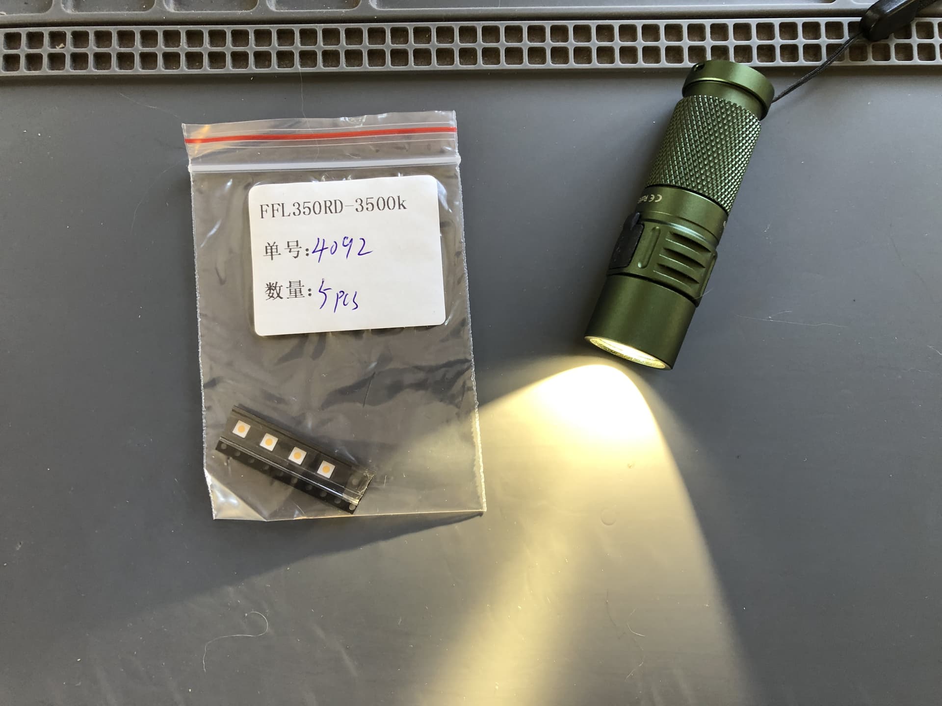
The emitter tested here was kindly made available to me by TLF user @Palladin, many thanks for this at this point!

Visually, the FFL350RD is kept very simple. The orange-yellow illuminated surface is embedded in a white silicone layer. The substrate is light gray. Slight soiling of the LED (taken directly from the cut tape) is visible.

The luminous surface is interesting. At a few mA operating current, the phosphor appears yellowish, but only in a square pattern. Outside of this - the corners protruding beyond the round luminous surface - the phosphor appears much bluer. In addition, light appears to shine through the white silicone layer in a square pattern around the round luminous surface. This should reduce the luminance.

It looks a little as if a square LED chip has been used to create a round luminous surface with a circular cut-out.

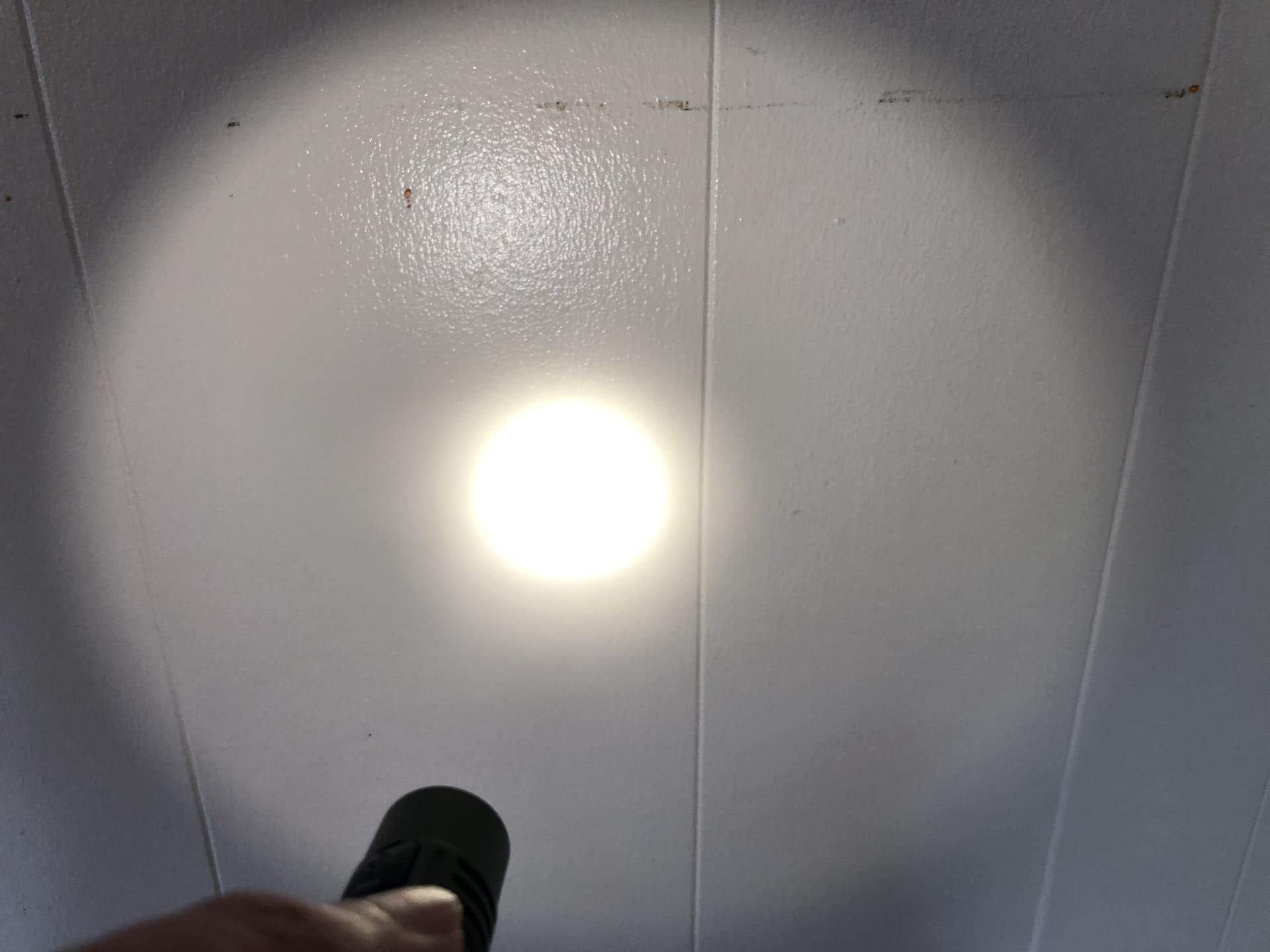
Particularly noteworthy is the light shining downwards through the substrate (!). This appears to be made of either plastic or very translucent ceramic and has not yet been seen with this intensity in a high-power LED (see picture). This effect is better known from LEDs in 2835 format or PLCC.

The footprint offers no surprises. The beveled edges in the thermal pad indicate the cathode. Such reductions in the heat dissipation surfaces should be viewed critically; they further reduce heat dissipation, which is already severely limited due to the small 3535 footprint. A marking on the top or a beveled corner of the anode is more advisable here.


  • Maximum reached at 8.2 A, at this point 1139 lm @ 3.91 V
  • Power at maximum 32.1 W
  • Efficiency at maximum 35.5 lm/W


Data for 25 °C Tsp (at 85 °C the luminance values are around 13 % lower).


Due to a lack of official performance information and data sheets, no official maximum values were specified. However, some observations can be made.

Compared to the FFL505A, the FFL350RD has a slightly higher efficiency. The Vf is very high. It is noticeable that both the luminous flux curve and the voltage characteristic deviate from the FFL505A. The plateau that forms before the maximum possible luminous flux is reached is also interesting. Either the phosphor mixture used becomes saturated above a certain luminance or the Tj (thermal junction) is lower than 150 °C, an effect that was particularly noticeable with the previously tested Moonleds MN-S3535 with 98 CRI. As the maximum current achieved corresponds to that of an LED in 3535 format (especially considering the high Vf), it can be assumed that the phosphor is saturated, another feature that clearly distinguishes it from most LEDs on the market.

It can therefore be concluded that the FFL350RD comes from a different manufacturer than the FFL505A.

However, the biggest problem became apparent after the luminous flux test. After around 3 minutes at the maximum possible current of 8.2 A, the efficiency was reduced by around 8 % at lower currents. This again indicates massive ageing of the semiconductor at (too) high currents, whereby degradation/alteration of the phosphor cannot be ruled out. In this respect, operation at over 5-6 A is not recommended. As Fireflylite does not provide any information on the maximum operating currents permitted (it only mentions “10 W”, which implies around 3 A), particular attention should be paid to the operating current when using in lamps in order to avoid premature ageing.

The luminance is lower than that of the FFL505A 3500 K, despite the higher luminous flux, which is consistent with the anomalies of the luminous surface (which have an influence on the total light emitting surface).


Despite the observed anomalies in the luminous surface, the beam is perfectly fine and also free of color distortions in SMO reflectors as known from some LEDs (sometimes just called “Cree rainbow”). Only rings can occur - as with most LEDs with a small luminous surface - depending on the calculation of the reflector.


The color rendering is very high. The specified 96 CRI is reached.

However, the light is subjectively less pleasant than other LEDs with a similar CCT. This is probably due to the duv of 0.0011 and above all to the CCT, which is significantly higher than 3500 K. The LED tested here should actually be specified with 4000 K. With this CCT in particular, a negative duv is absolutely essential, as greenish tints are particularly evident here even with a duv close to 0.


  • Ra: 96
  • R9: 94
  • CCT: 4024 K
  • duv: 0.0011

The FFL350RD remains somewhat in the shadow of its bigger brother. This is due to the high Vf, the significantly higher CCT than specified and the subjectively perceived slight green tint. There are also anomalies on the illuminated surface and a slight reduction in efficiency after operation at high currents.

The beam, on the other hand, is perfectly fine and the LED can be used in optics without any compromises. It should be clear that these LEDs do not necessarily have 3500 K and the duv can also deviate slightly. In addition, these LEDs should only be used with drivers with maximum current limitation.


Thank you for reading this test. :slight_smile:

Greetings, Dominik


v1.0.2
10 Thanks

Great test again and as i was just finished installing JlHawaii’s 6500K brother of this exact emitter (i wonder why FF doesn’t have them) in D3AA and HDS Rotary i can say it’s waaaaay better than 3500K, the one you have in test.
I’ll get some Opple meassurements later on or tomorrow latest.

1 Thank

thank you… at about how many lumens was that duv measurement? Im wondering if lower output has higher DUV, because

the one I tested at about 50 lumens read much higher DUV on my Opple, 0.0069

I disliked the tint so much, I put them in the garbage so no one else would be permitted to suffer such positive Tint Duv


The Opple said the CCT was 4900K, 11% higher than specified 3500K

hotspot was quite small from an SC21 Pro Reflector

1 Thank

Great testing, it is appreciated!

What do you think might have caused the gigantic corona around the hotspot?
Normally I would assume focusing issues (perhaps an odd LES height?), but you mentioned there was side-emitted light.

1 Thank

At around 80-100 lumens (operating current 350 mA) - it seems that these LEDs have some huge deviation in duv or CCT, despite the description on FFL’s website (duv +0.0004 to -0.0004)
In your case this specification was clearly missed. (But also in my case.)

It could be some sort of focussing issue, but keep in mind that these pictures are not made with high-tech camera, just with a smartphone (without HDR though). But the corona is somewhat huge with this LED. Could be also a thing with the sideways emitted light ((both downwards towards the MCPCB and laterally upwards next to the round LES).

The odd LES height was only present with the 6500 K FFL505A I tested earlier.

2 Thanks

Out of curiousity, what color was the centering/focusing ring used?

Also, I wonder if painting the sides of the LED black would be useful to figure out if it’s the side-light. Perhaps with a paint marker, as most other markers are too translucent.

I only use white gaskets.
I could do a test with black paint but since this LED was more underwhelming for me I don’t know if I do this…

Yeah, you are right it might not really be worth the time to mess around with markers on the side of it.

It would be interesting to see if a black gasket makes a difference though, it could be an interesting factor for improving the beam other LEDs with side-emission problems like the XP-L HI gen2

Since black gaskets are not as common I have to check if I have one. Maybe I will design my own and print it with black PETG, but I don’t know when I will do this.
I am more interested how this LED is designed (LED chip), maybe I will do some surgery the next days :sweat_smile:

2 Thanks

The lights I buy from Convoy have black gaskets every so often, you might be able to get some from Simon.

Either way, more information on these round die LEDs is something to look forward to. I wonder how it compares to an SFT25R in construction.

Yeah, finally a good use for my digital microscope. It’s been a while since the last forensic investigation :smiley:

I ordered some SFT-25R from Simon, but tbh I am expecting the worst in terms of tint (and maybe Vf). The luminance is likely to be quite high, but I don’t think this would be the next top tier LED for general use.

2 Thanks

imo the “corona” in this pic IS the hotspot, and the bright center is an artifact:

fwiw there was no bright artifact in the hotspot w the SC21 Pro reflector using the FFL350rd 3500K:

I just did not like the greenish yellow Tint:

Definitely not. If the picture has some exposure time as your picture the beam would look the same. I think the beam is because of the smartphone camera which still has problems with high contrast.

my photo is also from a phone camera… but the LED is in a different test light, with a different reflector than your test…

I don’t have words for this. :flushed:


It is actually a rectangular illuminated surface. A round glass pane was placed on top of this and the area around it was filled with white silicone, which created the design we saw earlier.
I have never seen this before, and it seems extremely illogical to me. After all, this eats up a lot of efficiency because part of the luminous flux is simply lost (at least it can no longer be used for the lighting in the optics).

Does FFL realize that they have been given an LED that could actually be much more efficient if it had been designed properly? I don’t want to accuse the manufacturer of anything, but somehow I get the impression that hardly any effort has been made here.

Fictitious dialog with the contract manufacturer? :smiley: “FFL wants a round illuminated area in the 3535 LED” - “shit, we don’t have round chip for 3535 LED” - “well, let’s just take the rectangular standard flip chip design and cut it out round and mold the rest with white silicone” - “perfect, no one will ever notice this, for sure”

17 Thanks

Wtf this was not what I expected lol

1 Thank

I am simply speechless.


The FFL350RD is basically a completely different LED after exposing the remaining LES. The luminous flux is over 60 % (!) higher than before.
The Vf is slightly higher, although it should be noted here that the LED has already been driven to the maximum possible operating current several times.
Either way, the maximum possible operating current is now significantly higher, which is also unusual only by removing some silicon layer.

The tint has changed massively after the operation. From a subjective green-yellow tint at 4000 K, it has shifted to a very nice rosy tint at around 6700 K, presumably because of the blue areas at the edges. The latter also provide a beam similar to the XP-G4 with dome, which doesn’t look very nice in flashlights (blue edge around yellow spot).
The CRI has changed and is now below 90. The light quality looks good, nonetheless.

I wonder whether it makes sense to inform Fireflylite about these massive differences in performance. :thinking:

6 Thanks

Here is the FFL350RD without any phosphor or glass panes on top:

Just an ordinary rectangular LED chip in flip chip design. So I can conclude: not a real round die LED chip, but just a fake to look like this.

11 Thanks

It looked like the FFL505A 6500k and the Yinding “6500k” 95 CRI glass-version were not that far off from each other efficiency-wise.

Wasn’t the FFL505A designed much the same as this, that it was really a rectangular chip that was masked? Whereas the Yinding “6500k” was an actual round phosphor application… At least I remember somebody reporting taking off the film on an FFL505A and claiming it was not round underneath.

So is there more to the story about the efficiency here? Is it that the Yinding is somehow inefficient despite being round die?

1 Thank

Are you able to find the source of this? I will check the internals of the FFL505A in the next days.

1 Thank