He has it listed on page 1. They are not available yet, though.
We just have to keep waiting.
He has it listed on page 1. They are not available yet, though.
We just have to keep waiting.
LX has nothing to do with TA, its complete new drawn design with all my previous tweaks
its based on Narsil Triple channel/Bistro HD OTSM of course the end product is similar in some ways
.
lets have a look on TA 22mm for example


just to mention if you would solder the MOSFET this way around like seen here it would short 180° flipped
You can get it from mount electronic for $25
No you can’t. He’s not selling them yet.
So it’s a lot different. Okay.
Are you still going to be making the TA based drivers or switching over to the newer LX drivers?
I had a request on 12mm driver
had it a long time on the to do list, but hoops driver picture was the trigger to shring my bigger drivers,
but keeping
- full e-switch firmware functionality (switch and indicator LED)
- and OTSM support (C1 and big 0805 C2 plus voltage dividers)
I put all goodies for OTSM and e-switch light onto it
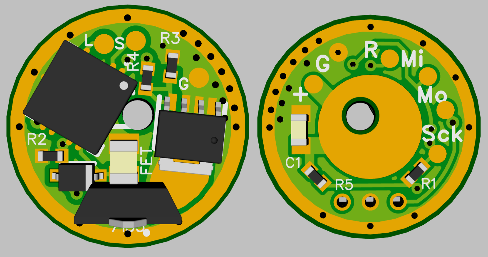
no boards produced yet, will order from Oshpark asap
That must be packed in reality Lexel. 12mm is pretty small. Nice work. :+1:
It reminds me of the layout on the Darkside Nymph driver with the 7135 chip soldered in the upright position to save space. But it isn’t exactly the same. Components are different. Yours also has (re)programming pads. Wow! Nice touch! ![]() :+1:
:+1:
I did not rationalize any parts away it has full OTSM support and 2 caps
If the 1mm copper area removed its 10mm but then grounding is an issue
Can’t some of the green material near the edge be scratched off and then have a bit of solder between the driver and the body?
Like maybe near that circle at the top of the ‘G’ where there’s some free space
sure this would be possible to get grounding
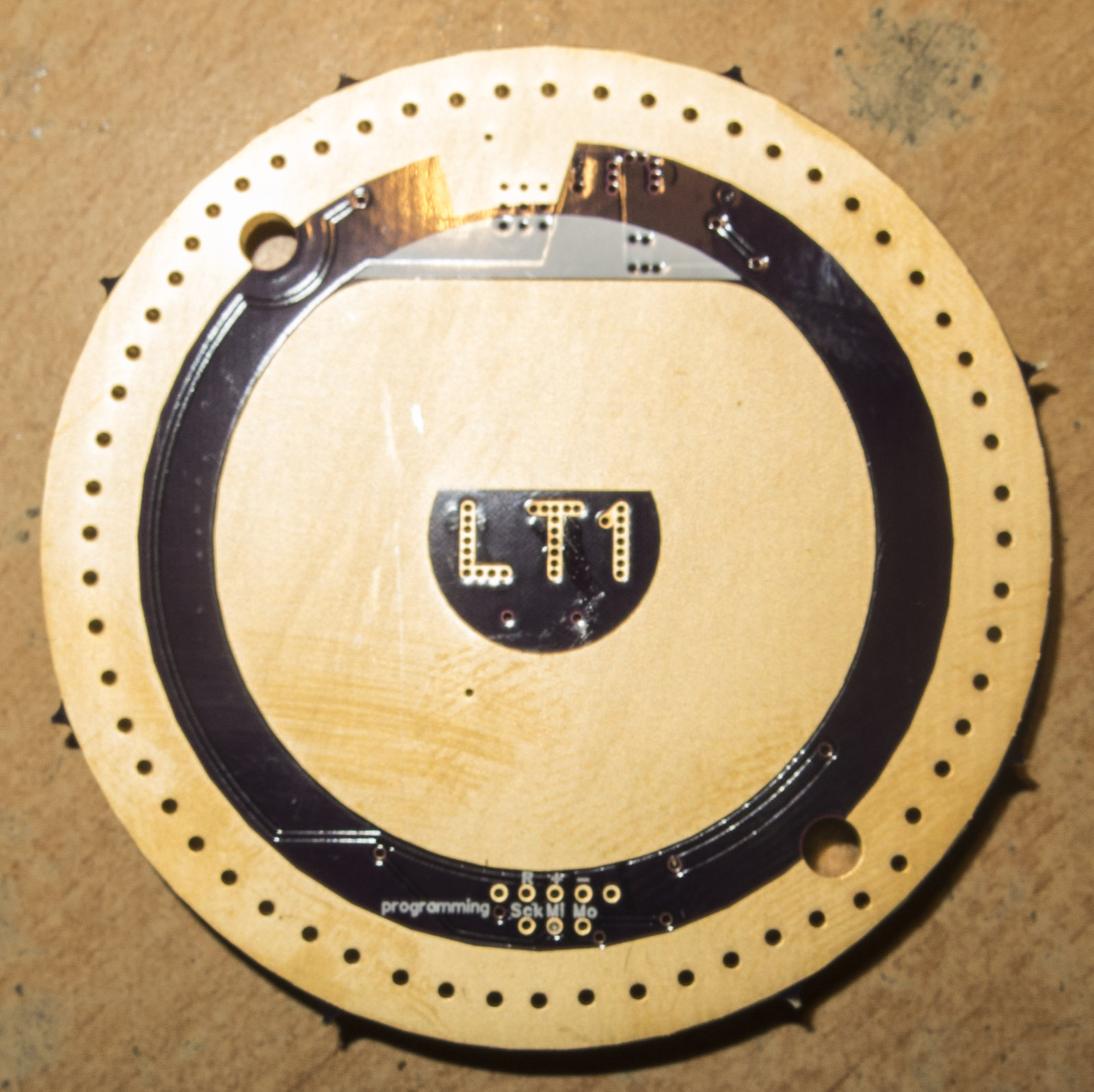
first prototype just soldered

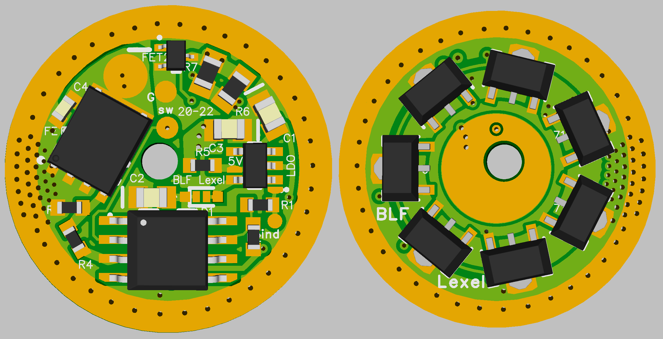
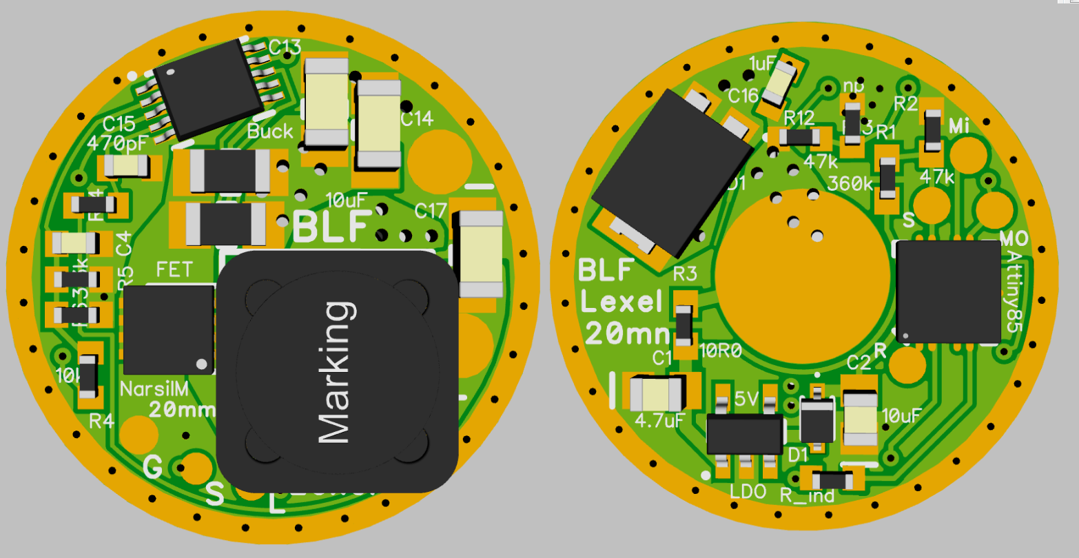
new 20mm 8A buck driver (old one 6A)
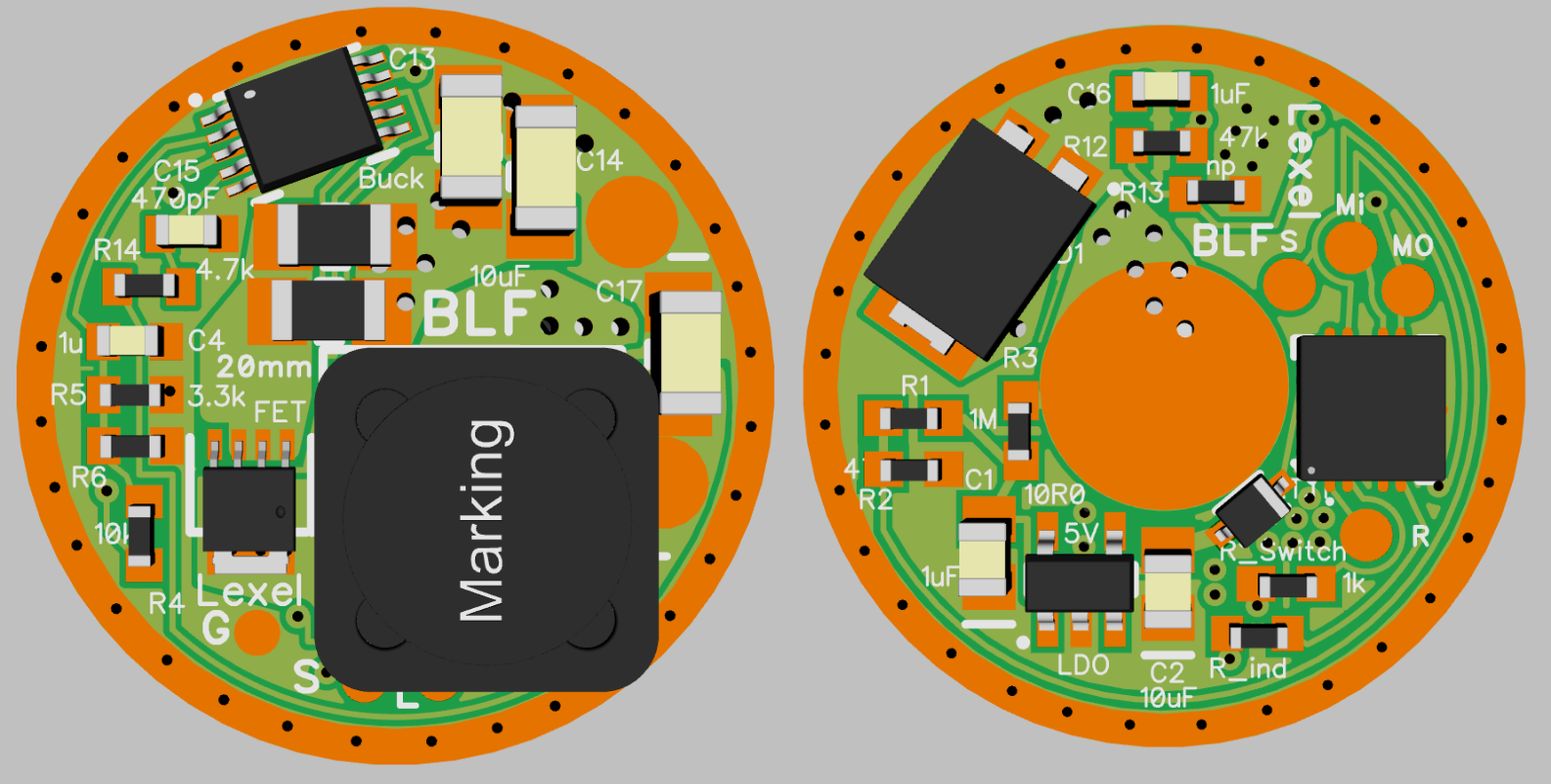
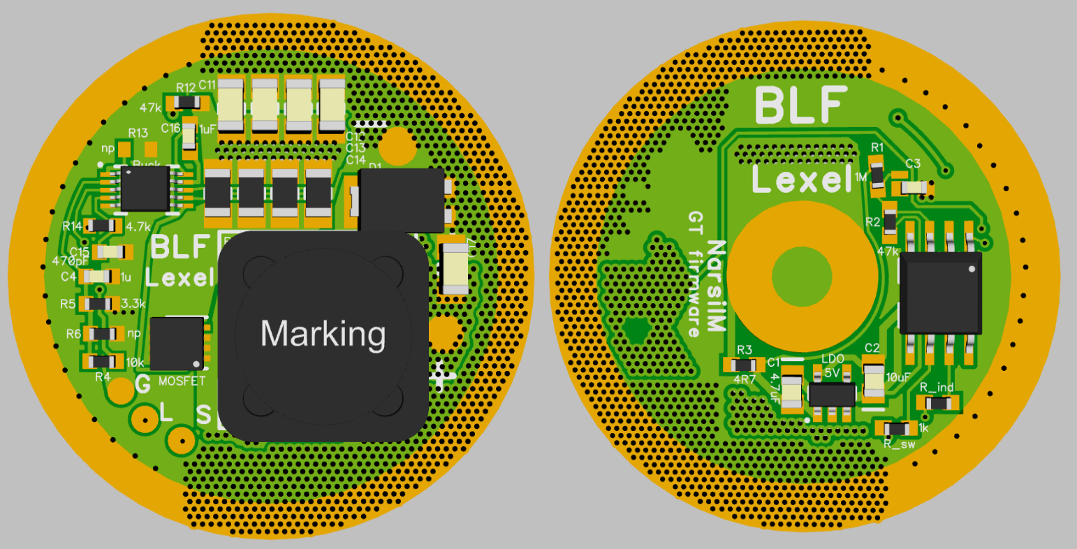
new 33.5mm SD75 drivers DD+small current FET and 8A 2-4S Buck

Nice stuff ![]()
OK… There’s a moose on that buck driver…
![]()
![]()
![]()
![]()
![]()
![]()
![]()
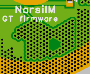
Geez, that’s a lot of vias. Are they needed or is that just cosmetic?
I reckon your horsing around Hoop. ![]()

A proud buck, just grazing in the arctic tundra.
I raise you a Trojan horse. ![]()

Pretty fly for a buck driver.
not really needed as we talk about 1-2W heat depending on current and voltageges
but guess adding thermal viases dont hurt, unless you try to solder on them with too small iron