Okay, point taken.
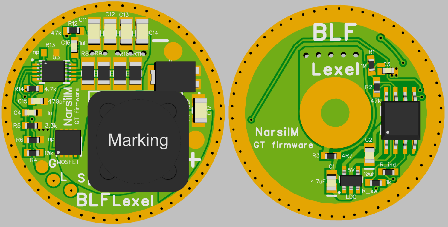
But you still make the fibre glass PCB conduct heat better, ALSO TO THE OUTER PERIMETER, by drilling out the fibre glass and inserting copper vias.
Lexel explained this too.
He even tested it.
there are very reliable things to improve it, but they can easily escalate the price of the board
1. add viases —> at our quantities for free
2. 2oz copper —> relative cheap but needs thicker traces and solder lands
3. 4 layer —> in chineese fabs increase costs quite a bit
4. ceramic PCB replacing fibre glass —> expensive
5. special thermal copper layer like 0.3mm inside the board —> very expensive, needs big batch to be produced
To lexel, do you have these drivers for sale? Do they do 6V 6A output?
Not for sale yet. In previous tests he said it would do 6A output. At lower battery voltages the amp draw from the battery could get as high as 15A-16A IIRC, so it can put out some real power. Of course, the output level can be turned down to what you want. I think it’s a resistor swap to limit output. We just have to be patient.
BTW, I’ve been waiting about a year, so do not hold your breath. Lol
thank you JasonWW. I see Loneoceans also has similar driver, but it seems it is also not for sale yet? Lexel can I build one myself?
Loneoceans only designs, he does not build for sale.
Basicaly I could build them but I got too much to do eith current sales, design and mods to work on them, same with high current buck
To build and sell untested drivers is not really a good idea, they may work in the beginning
Interesting.
Is it possible to build it myself with your pcb and list of parts and program code? Small 6A boost driver is very useful for me. Thank you lexel. It seem some people like you, loneoceans, schoki is making such a driver, but so far i only see loneoceans with working design and flashlight. I am hope to build one myself.
Mtn e is currently making and selling a boost driver, but it is only 17mm and for clicky lights at the moment. Bigger sizes and e-switch versions will be sold soon.
Thank you jasonww! Is it this driver?
I think I may buy one. But I will like to try the 6A version made by lexel since it is much more powerful at 6A compare to 4.2A.
yes a lot depends on the used Bost chip and thermal cooling, on my driver I would strongly suggest to pot around the Boost chip with aluminum oxide glue
you could try the same on MTN driver
Basically whats limiting output current atm is thermal properties of the board
4.2A? That must be due to its small 17mm size (along with the 1.3A 12v output). The bigger ones are 6A just like Lexels (12v also goes up to 2.5A-3A). Roughly 50W seems to be the most you can get from these smallish sized boost drivers.
Lexel, can your 24mm drivers be sanded down to 23mm?
I have the Amutorch VG10 that takes a 23mm driver, and I guess one of yours would be good to fit in, if I can sand it to 23mm! BTW, will it work fine with:
a) Forward Clicky Switch
b) OSRAM KW CSLNM1.TG – 1mm2
Thanks in advance!
BTW, about the driver for the BlitzWolf BW-ET1, I will let it stay still until I get a good solution! Thanks for your answers, though ![]()
Buck driver easily sand down
the FET DD you may be careful with component side as then some are pretty close to the edge like 1mm
for 2S battery configuration a Buck regulated is possible but not yet for 1S
Hum…I guess I will want a FET DD (like the ones you sold me before), because I will use it just for one 18650 cell and clicky switch on the tail.
Am I correct in this choice?
If needed I can sand/file the host a little bit (on the inside), but there is few space. I guess using a 24mm driver will be better than using a 22 mm one, as there is not retaining ring nor “pill”.
1mm² Oslon needs regulated output or will burn
e-switch or clicky is just UI, if the LED works with battery is on DD an equasion between
battery voltage sag + conduction voltage drop
and
LED voltage
when both is equal you get a current which drops with battery charge status constantly
a battery with higher internal resistance has more sag, but this wont do the trick on an led with that low forwqard voltage and to about 4A limited max current
What driver will be suitable for driving an osram cslpm1.tg at 7 amps in a convoy L2
30mm buck as shown in first post, its listed under L6
Will it fit in an L2 though or only L6?