That’s the main issue, as it will heavily alter the spectrum based on geographic position, time of the year, weather condition etc…
I’ll meet with koef3 soon, and buy a halogen light with a spectrum he measured from him to use as a calibration source, as well as 2 or so LEDs for double-checking after.
Central europe, so no, it will never be perfectly overhead.
Are you in astrophysics? I had a lecture about it at uni, was pretty fun, but I ended up going into a different field eventually. Still led me to work with spectrometers, but sadly I have no more access to the labs ^^
A known, calibrated lamp is probably a sensible way to go if you have a really good stable power supply to drive it. I would always be worrying though if it was the sensor, the lamp or the power supply that was drifting whenever I saw a change. Over long time periods, I do not know if the lamp bulb or the spectrometer is likely to be more stable. Maybe by using another external photometer (need not be a spectrometer) you can convince yourself that the lamp itself either is or is not stable.
You mentioned starting with halogen bulbs. I wondered if a really simple old-style incandescent would be a better black body. (That is if you can even find one! Maybe they still sell “appliance bulbs” meant for inside an oven that are simple incandescents?) I had a very quick look using my XRite ColorMunki. I had two simple 60W incandescents and a 40W halogen that claimed to be “60W equivalent” output. They are pretty much the same and all gave black body fits in the range 2500-2600K. But then the ColorMunki is limited in wavelength range to that part of the spectrum that a decent black body in your ThorLabs plot, so this is probably not telling me much new or useful. Here are my three different bulbs. If nothing else it illustrates the variation to be expected between bulbs.
For the solar spectrum, there are very good models available to simulate the solar spectrum at whatever Sun position and altitude you like. For example SMARTS from the US NREL could be worth a try. https://nrel.gov/grid/solar-resource/smarts.html
Ultimately though, this is just a really difficult job to get right. Absolute spectrophotometry is hard work, even with lab grade equipment. We still have some 1-2% bumps and wiggles in one of the instruments I work on that I have never been able to fully calibrate out.
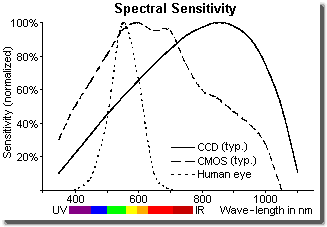
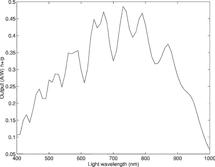
From the plots you show, this CMOS detector clearly has an ugly spectral response. Calibrating that is going to be a challenge. I confess that I have only ever done this sort of thing on far more expensive sCMOS detectors. I found a really nice plot showing that, here:
It is clear that some have very complicated QE curves, like you are seeing. By comparison, something like the back illuminated pco.edge 4.2BI has a beautifully smooth QE curve. I have used that detector and calibrating it was quite easy!
Anyway, I am glad you are putting in the effort on this. I am tempted to buy one of these devices myself, so am interested in how you get on.
Hello, I want to know what is the “Bayer filter”, actually I can check it out from wikipedia.
you mean the hobbyist used the same sensor as those used in cameras(CCD & CMOS)? he just removed the Bayer layer to make it more sensible to the lights? then why the cameras need the Bayer layers? actually I know there is a startup in Europe that is developing camera sensors which can sense the whole visible range of spectrum for EACH pixel, that is horrible. I think it’s intended to achieve better quality of photographs.
the website is https://www.spectricity.com/
the hobbyist used a camera level sensor, so the “Little Garden” device’s main cost is for the sensor part right?
The Bayer filter is basically the difference between a monochrome and a color CMOS - a color-filter layer that filters all but the wavelength range for one color from the incoming light per subpixel.
By removing it, all 3 sub pixels are exposed to the entire spectrum, instead of just red/green/blue.
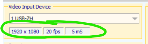
Got my Little Garden today. Weirdly, it won’t work on Windows 11… The camera driver is installed, the camera is started according to the Device Mangler, but the 0.2 app won’t read from the camera. These fields won’t go live and there is no image or spectrum.
It seems to work fine on a different Win 10 machine, which is where that screenshot came from.
EDIT: Fixed it. It was the Windows 11 privacy controls. I had disabled app access to the internal camera, but that actually applied to any external camera that would be connected in the future, too.
@ebastler Is that spectral response in your first post actually representative for a typical CMOS sensor? Haven’t read the paper where this image is from, but it seems to be about some sort of custom sensor. Other response graphs I’ve found are much less dramatic- e.g. this one
Hi Moritz, actually I ordered one, still on the way. what about your latest calibration attempt? I actually can’t full understand what you stated in your post. A fluorescent lamp is enough for calibration? otherwise why Lao Kang only provided a fluorescent lamp?
Hi Steve! I sold it to a friend of mine and forgot to order a replacement for myself, so I have not continued my work with it so far
Basically it needs 2 calibrations. One for the x axis, so you know which pixel is which wavelength. This is done with a Hg lamp, which has 2 strong mercury emission peaks at a known wavelength. This allows to calibrate the x axis. This lamp is included and works well for this part.
The other is the spectral response. The sensor has different sensitivity for different wavelengths. So the same incoming amount of light at 500nm and 700nm does not produce the same peak height on the readout. This needs an additional calibration of the spectral response, and this is what I was stuck with. I tried, but the results were mostly making it worse, not better.
I think Lao Kang mainly aimed this device at school teachers and parents to do science experiments with kids, where it is important to see the correct wavelength, but not very important to see correct peak heights - so he did not care much about the response calibration. But since we try to compute DUV/CCT/CRI from it, we need it…
thank you for you explanation. basically you stuck with this graph right? y-axis calibration, why not just normalize the spectral response with coefficent for each nanometer?
btw, just now I consulted with Lao Kang, he replied “no need for y-axis calibration”, the coefficients are already embedded in the CCT&Ra calculation software.
I do not have the graph for the particular sensor Lao Kang used, this is just taken from some other paper. His sensor originally had a color filter which he removed, so the manufacturer does not offer raw sensor curves.
I tried this, it gives very strange readings with my spectrometer. Don’t know why.
then this is indeed a problem.
and actually every sensor is different from each other in terms of the response graph.
expand from this, I think every camera needs to do calibration(after all Lao Kang used a 1080p camera sensor, although he removed the Bayer filter layer), I think it’s sophisticated to do calibrations for cameras.
Hi, I still want to ask you some questions:-)
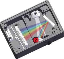
Lao Kang said he actually used a 1080p camera sensor, then removed the Bayer layer from it, then the sensor can sense perhaps from 350nm to 1000nm range waveforms(assume it’s in this range), I am wondering how it’s achieved? as far as I know, the sensor’s each pixel is the same, it only detects/senses the strength of the incoming light, how it can distinguish between different wavelengths? the sensor’s each pixel is mounted with different filters like as7341 does?
A diffraction grating splits the light and distributes its spectrum over the length of the sensor. The position on the sensor determines the wavelength.