I recently had my 1000th post giveaway, which was aimed at members that were new to the community and/or did not have the tools/ability to mod a light.
The winner was to send me a light of their choice, & I would perform the mods they wanted, make a build log, then forward it on to them.
The winner was MauiSon, who chose to send me a Courui D01 for a work-over. The draw was back in July, & some of you may be wondering why I'm only just posting the build thread now.... let's just say that the light was originally ordered from Ge@r Be$t.
Cut to several months later, with the PP claim behind him, MauiSon's light arrived quickly, after ordering from KD. He had also sent a 32mm Noctigon & an XPL HI V3 2B from IOS, which had been gathering dust, awaiting the D01's arrival.
I've done a few D01's, & have evolved the process into what I believe to be a pretty solid light. Of course, this build is similar to my other D01 thread, but, hey, it's the same light :)
For MauiSon's build, I incorporated a couple of new ideas, & also used the ATTiny 85v, coupled with TomE's awesome user-configurable firmware.
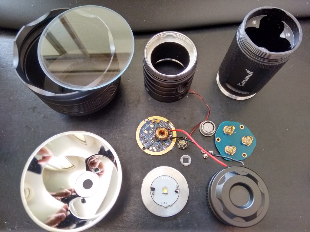
Here's the light stripped down. This one is a reasonably good example, with just a few minor imperfections.
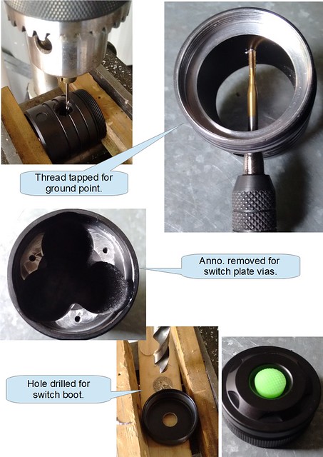
I started on the body mods first;
A hole is drilled & tapped in the thickest section of the driver cavity, which enables a dedicated ground lead to be attached to the driver. This overcomes any potential grounding issues with the standard press-in driver/contact plate arrangement.
Moving to the back of the light, I removed the anodizing where the switch plate via contacts the body - not really necessary, but an easy step to do. As a lockout switch will be added to this light, a 13.5mm hole is drilled through the tailcap to accommodate the switch boot.
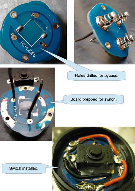
With the body prepped, I moved onto the rear contact board.
Each spring was bypassed directly to the switch leg with 22awg silicone wire, leaving the original via's intact as a backup. The KAN28 switch is soldered to the original traces, as well as being secured by silicone rubber adhesive. The three ground points are also beefed up with 22awg wire from the switch leg to the grounding screws.
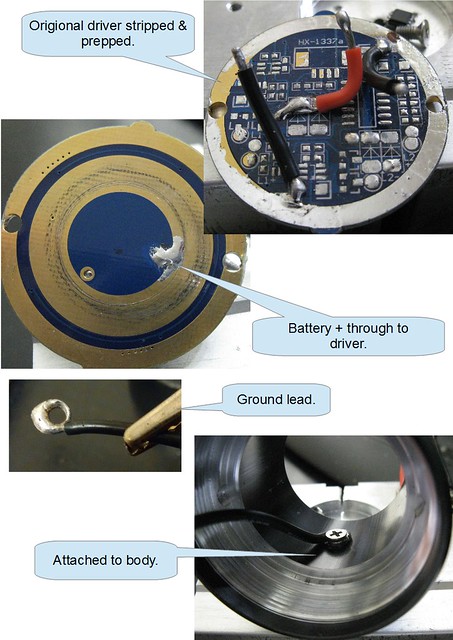
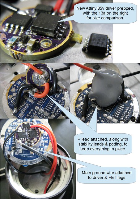
Moving onto the front board, the components were removed, & it was prepped to accept a piggy-backed Wight Fet+1 driver.
The Batt + is taken through the board from the battery side, using the existing via, & then the Ground lead is attached to the body with a machine screw. The end of the Ground lead has a small Nangj spring cut in half & soldered to it.
The other two wires are to act as a support to keep the driver in place, as well as providing additional grounding. All wires here are 18awg.
The Wight Fet+1 driver was assembled & tested, prior to attaching to the contact board. The 22awg LED+ wire is also attached the base of the driver, then silicone rubber adhesive is applied, & the driver is flipped over, & the silicone is allowed to set.
On top, the LED- wire is attached to the Fet drain, & the ground wire attached to the driver ground & also directly to the Fet legs. The original LED wires were trimmed & re-used for the E-switch.
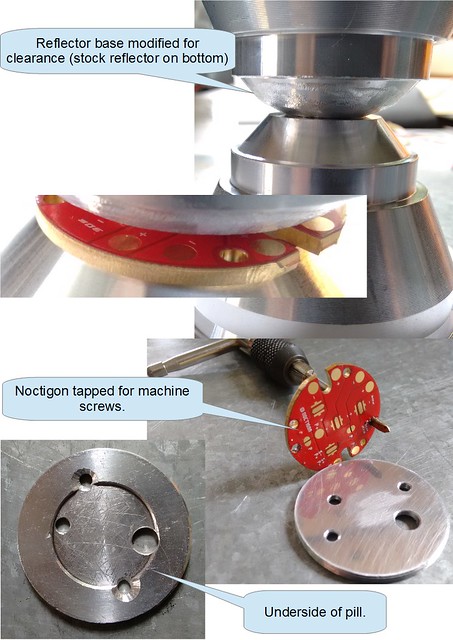
The trickiest work involved with this build is modifying the reflector base for wiring clearance. I use a grinding die in the drill press, & manually rotate the reflector by hand, to gradually reduce the base diameter. The picture below shows the modded reflector base, compared to a stock one.
Doing this allows the reflector to sit flush on the 32mm Noctigon, so the LED is not shrouded by the opening, & allows clearance for the wiring connection, eliminating the chance of a short.
I tap threads into the existing holes in the Noctigon, then mark & drill the pill, so I can attach the Noctigon with machine screws from the underside of the pill. I also drill out the wiring hole slightly larger to accommodate the bigger wires. The pill is inverted, in order to raise the LED, & utilize the flat surface.
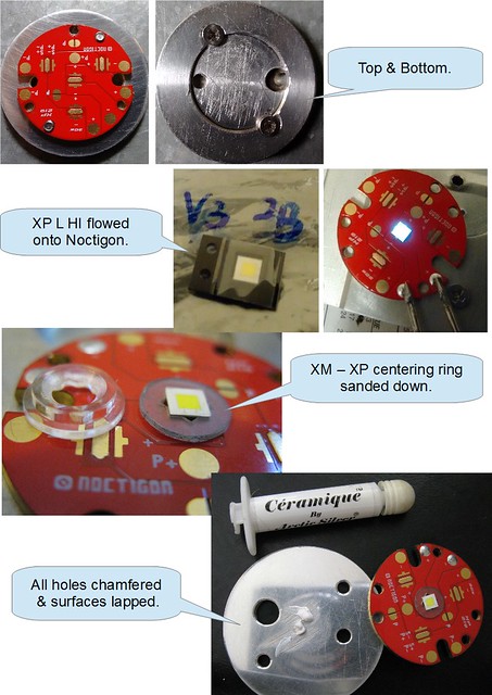
After the machine work, the XPL HI was flowed onto the board & tested.
I then sand down an XM-XP centering ring, so it's no higher than the surface of the die, which is then attached to the board with a very small amount of 'super glue'. The outer diameter of the centering ring also needs a slight sanding to fit neatly into the reflector opening.
Finally, all of the holes are chamfered, & both surfaces lapped, before using a thin smear of thermal compound, & fixing the Noctigon to the pill with machine screws.
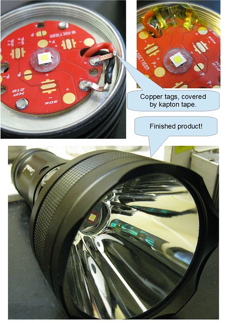
The pill is then screwed down tight into the body. Some D01's will run out of thread & not tighten down, necessitating the use of a locking ring, but this particular one did not require it.
I made some copper tags for the LED connections, as I feel it's a neater solution, & helps maintain the reflector clearance, as opposed to soldering the wires directly to the board.
The LED wires are then fed through from the underside, & soldered to the tags, clearances double checked, then kapton-taped for good measure, before assembling the head for the final time.
The E-switch cover is then re-attached, & the driver board is pressed back into place, after double-checking the tightness of all the machine screws.
The main threads are cleaned & lubed, & we are ready to insert some cells & fire it up!
With this combination, & using Samsung 25r's, I measured;
- Lumens; 1616.
- Throw; 1131 meters.
As of writing, MauiSon's D01 has landed on his soil, & should be in his hands soon!
:beer:
