Mod: HD Defiant 3C Super Thrower 18650 Driver and Emitter Swap

Getting an HD Defiant 3C Super Thrower for me involved a recent business trip to SFO. And I always fly carry on (no checked bags). I sort of thought that part through after I got back to my hotel with the flashlight. Will they even let me carry this 'club' onto the plane???

At security there were some questions about it: "Sir we need to open your bag. There were some items that we could not identify on the X-Ray." Oh Boy. Being a frequent business traveler, I remain relaxed during the security scan procedure. It's not the first time I've been asked to search through my undies. No problem, help yourself.

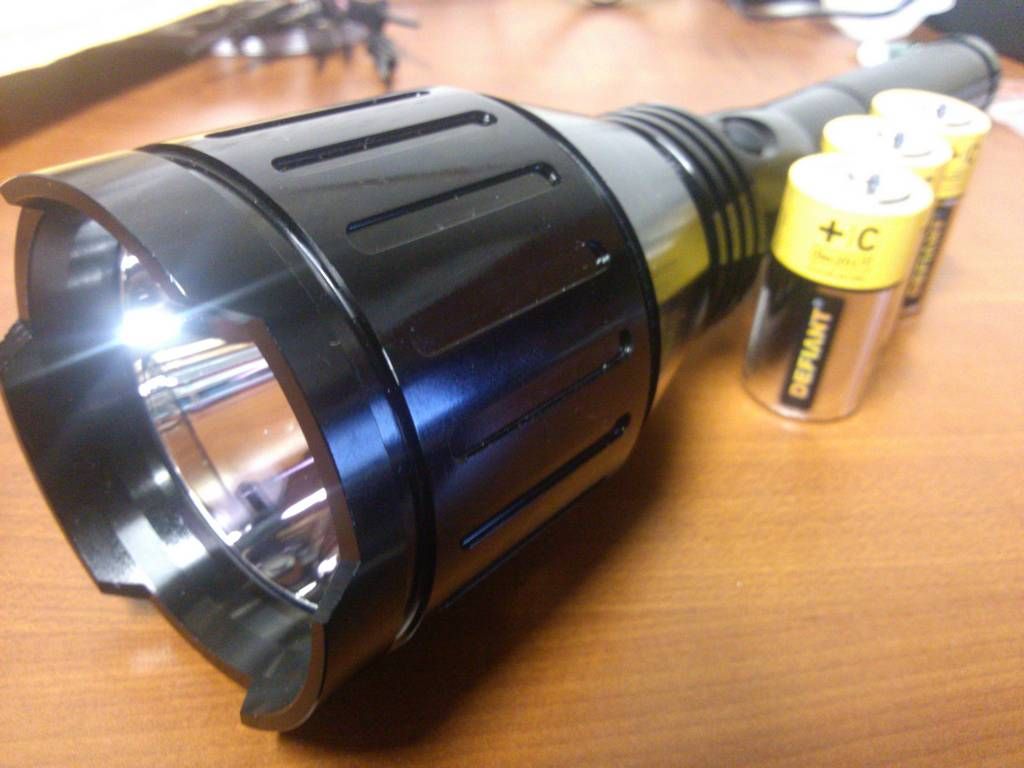
I had the light in two pieces so it would fit better.

The first piece found was the battery tube. He didn't recognize it: I tell him "It's a flashlight battery tube".

Setting it aside he fishes out the head. "OK, now I see," he holds the two pieces together, "that's a big flashlight".

"Yeah, it is. I collect flashlights and this one is not available in Canada so I couldn't pass it up".

A small chuckle, "One second Sir, I need to show the X-Ray operator so she knows what it was for next time".

Holding back a laugh (thinking, as if this will ever happen again) "Sure, no problem."

He walks away and I start putting my bag back together.

When he returns he hands me the pieces "All yours, have a great flight Sir."

What I nice guy. I've heard a lot of different and less fortunate stories about confiscation at security. I'm happy to say that mine had a good ending.

OK, on to the mod. I've read a few different ideas for modding this light. Some include chopping, boring, new tubes, new drivers, MT-G2's, parallel batteries, etc. etc.

I decided that I wanted the light to look virtually stock on the outside. The only exterior change is the lens. I picked up two of the 64mm coated Leica lenses from Phil. A great deal from a great guy. I do hope he gets more flashlight parts someday.

I also wanted to make the most of the battery tube. Two 18650 cells will almost fill out the tube with about 1 inch to spare. Three 18500 cells would fill it the best, but their capacity isn't great and I have so many 18650 cells already, so 2x18650 it is. I'm too lazy to make a parallel adapter, so I needed a new driver.

The new driver will need to support 3C as well as 2x18650, so 3V to 8.4V operation is required.

I settled on this driver from Fasttech. Very nice driver, 3/5mode, selectable like the new NANJG 105C, but mode changing is not next-mode so it's even better. No visible PWM was a nice bonus. On 3C cells I still get almost full output; with fresh cells, about 70% of the 2x18650 drive.

One problem; the battery contact board is too big. I ended up stripping all two components from the existing driver and using that instead.

The driver itself barely fits up into the pill, but it fits. I'm a little concerned about it shorting against the pill, but the angle it's in there seems to keep things away from the sides. I may have to add something to prevent a short though.

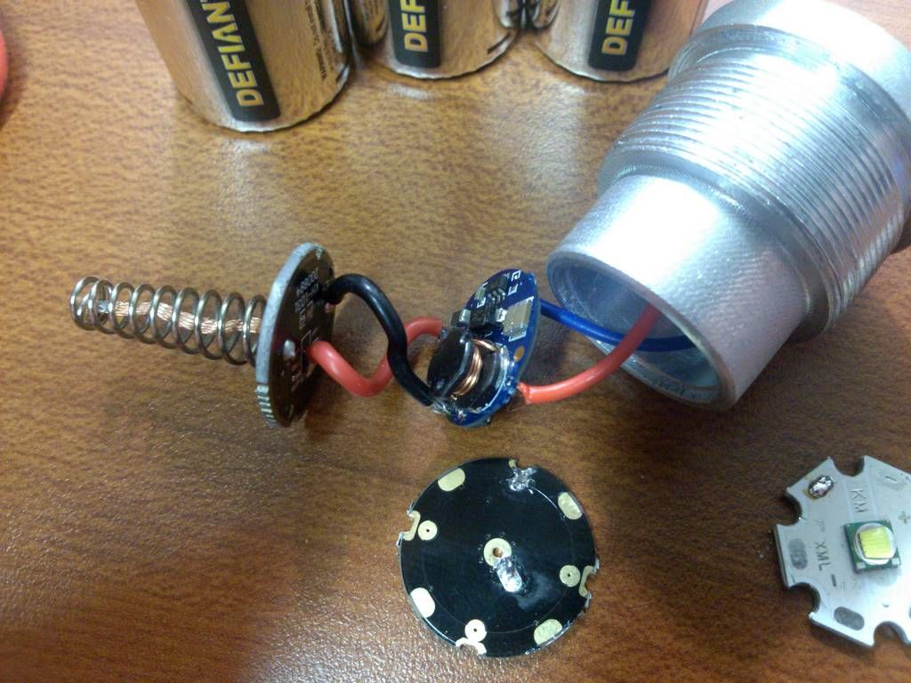
The driver has an R025 (0.025 Ohm) current sense resistor, which I did not modify yet. It is located right next to the black emitter wire. This is supposed to give about 2.8A at the emitter and based on the output, I believe it is close if not slightly more. With two fully charged Panasonic NCR18650As, tailcap current weighs in at 1.48A. So far, this driver looks good.

I also upgraded the emitter to an XM-L U3 1B, again from Fasttech. No point in doing all of that work just to keep the same emitter in there. ;)

For the battery spacer, since this is a side clicky you can use anything you want if you put it on the tailcap end. As long as it's electrically conductive and long enough, it doesn't matter if it shorts against the sides. I currently have a copper bolt in there.

The batteries are wrapped to hold them in place and prevent rattle. 3/4" PVC pipe will work fine too.

That's it! Lens, driver, emitter, battery wrap, and a battery spacer. Three modes (including a nice low), about 780 lumens OTF, and 56kcd for throw. I'm happy with it... for now. ;)

If anyone wants pics of something specific I'll try and take them.

Happy Modding! :) searchID8935

If anyone is curious, the three C cells were in a battery case in my bag. They didn’t even get mentioned by security.

Thanks for sharing Relic!

Nice alternative! Would be interested in how much voltage changes from charged after running it about 40 minutes. Plus, how long the run time ends up being (will it shut off with each cell at 3v?).

The poly tubing in the orig thread is perfect for inside the C tube. You might want to o-ring the 18650 cells, but I’ve not noticed any rattle with my limited use so far (1 cell plus 3” dummy). With no other mods and the IMR cell, it seems to be possibly slightly brighter than the 3*Cs.

Thanks for the information.

now swap that sense resistor and pump up the amps……. J)

I’ll post the runtime info when I get a chance to run the test. Based on the tailcap current of ~1.5A, I’d expect about 1.5 hours on high with reasonably good cells.
The Fasttech page claims it has a low battery indication/cutoff.
I use a soft foam wrap for the cells; no rattle here :wink:
With the old driver, a single 18650 or very fresh 3xC cells would drive harder than this driver (it was direct drive). Once the cell(s) dropped a bit, the new buck driver wins in the long run.

Soon enough my friend, soon enough. :wink:

What a nice practical mod. How does the light beam look brightness wise compared to the stock light? Mine stock running alkalines is only 1.6 amps at the tail. Its not quiet as bright as a good HD2010.

It out-throws my HD2010 (driven at almost 4A), but the HD2010 seems to have a slight edge in lumens. I still need to go to copper (maybe) and up the drive current. I’d like to get closer to 75kcd at some point, and hoping to not need an XM-L2 to do it. XM-L U3 driven around 4A on copper should do the trick. :wink:

nice work!

Nice! Thanks for sharing!

-Garry

Nice set up you built there. Gives a lot of flexibility. Thank you for sharing.

In general, can you get more performance and run time from serial config? I’ve always avoided serial, but saw in another thread about copper bases on xml2’s that the Vf gets too high for a single cell to effectively drive a high currents.

In an ideal world, serial or parallel offer the same amount of energy. Realistically, it comes down to how you need to deliver the power. if you need a lot of current at low voltage, it can be advantageous to go in parallel. If you need a higher voltage with less current, the serial cells can work out better.
Once you introduce power converters like Buck and Boost drivers, thing get a little more complicated. The efficiency of these can be variable based on the design as well as the input and output voltage (lots of variables to consider). Generally, a buck or boost converter in the 80% range is considered good, 90% is considered excellent.

I didn’t do a detailed analysis of this buck driver, but it appears to be in the 80-85% efficient range. Using this driver allows me to run at 100% output until battery depletion (3V/cell), if I choose to do so. The big caution here is having a cell imbalance that results in reverse charging the weaker cell (not good at all). Protected cells can almost eliminate this risk.

In a parallel setup with a linear driver, the driver efficiency is somewhere between 70% and 95% based on battery and emitter voltage, with the average I’d guess around 80%.
However, the output will not remain at 100% until depletion.
Once the batteries drop to emitter Vf + 100mV (regulator dropout) + switch/spring/wiring loss, the output will drop accordingly. For XM-L, Vf at 3A is around3.3V at 25C; XM-L2 it’s closer to 3.45V.
Example: XM-L with good switch/spring/wiring (100mV total), driven to 3A. When the battery is above 3.3V + 0.1V + 0.1V = 3.5V, the output is 100. When the battery goes below 3.5V the output will drop off accordingly. Based on the typical battery discharge curves, you would get 100 output for around half of the battery capacity.
It drops off 0.15V higher/sooner with an XM-L2. Based on the typical battery discharge curves, you would get 100% output for less than half of the battery capacity.

If your goal is to maximize the 100% output time, serial is the way to go.
If peace-of-mind/safety is the primary concern, then parallel would be better.
The alternative is parallel batteries with a boost driver, however these can result in direct drive while the battery voltage is higher than emitter Vf.

Wow, that is a lot of good info in that reply. Well presented and easy to follow too. Thank you for taking the time to respond in that fashion.

I was under the impression that one should match capacity and discharge curve even if using protected cells. I know “should” is relative to the risk one is willing to take. But it seems like the risk would be pretty low if relatively new, good quality protected cells, charged to the same voltage (within some range) are used.

Nice thing about your set up, you can go serial or parallel depending on your mood.

You’re welcome. :wink:
I didn’t even think of that; yes I could build a parallel adapter and run it that way too. Technically that’s three four battery configurations then:
3xC (or even AA) in series
1x18650
2x18650 in series
2x18650 in parallel
Nice!

I’m a total novice at this, but I’d like to try the emitter, driver, and battery mods. Are these mods too complex for a novice? Is there a tutorial on BLF that explains how to swap the emitter and driver? I have the battery+spacer figured out already.

I have no desire to ever run it on 3 C cells, so is that FastTech emitter/driver combo still a good one to use?

Would I be better off practicing mods on a cheaper flashlight? I have two Sipik SK68 clones, a C8 clone, an Ultrafire HD2011, and a Solarforce L2m that I could practice on instead.

I think this is a great light to start modding. This mod is very flexible and should be fine if you never want to run C cells (the option can still be there).
The toughest part of this mod is the soldering, which isn’t anything really small or risky. It’s just wires between boards.
Another area of concern that I haven’t addressed yet is the driver board fitting up into the pill. It’s tight but it fits, and there is a small risk of shorting. If it goes in at the right angle, it should be OK. A simple fix would be a single wrap of electrical around the edge of the driver board.
The emitter swap is optional. I did that to improve the output a little. Plus it was sitting here just waiting to be used. :wink:
A simple alternative mod is the driver swap only.
You didn’t ask for detailed pics of this process, however I think I left out too much detail for the novice modder. I will try to update the mod with detailed steps to update the procedure.
While I’m in there, I think I’ll put the emitter on a copper SinkPad and drive it a bit harder. :wink:
Stay tuned…

Thanks, I'd love to try this. I there an equivalent single mode driver though?

BTW, the emitter you linked to is a U3-1C, is that the one you're using?


Hi Gj, yeah that is the emitter I used, mostly because it was just laying around. I didn’t have XM-L2s at the time.
Im not aware of any single mode drivers that run from two cells and drive one emitter. Intl-outdoor may have one with that option that I don’t know about.

Thanks. Now, I wonder where my soldering iron is???

The amount of risk is strongly affected by how much care is taken. Someone who uses unprotected quality cells and is careful to check cell voltage regularly arguably runs less risk than another person who uses protected cells but runs them hard and only recharges them when the light's low voltage or the cell's protection circuit tells him to.