Can someone be so kind to measure how much current is a stock ThruNite TN31 pulling from the battery carrier on highest level? I did a mod to increase the current to the led in my TN31 but in all the exitement to finish the mod, I forgot to take a current measurement of the stock light, I really don’t want to reverse the mod just to measure it.
BTW I soldered a 0.12 SMD Resistor in parallel and the brightness increased, according to the german forum, it should be delivering 4.65a to the led now from the stock @3.7a.
Thanks Spasmod! Your stock measurement seems about right, so there is an increase in current with the resistor mod, mine stabilized at around 1.68a which translates to about 4.5 - 4.6a to the led.
ILF its 1.38a x 3 18650’s = 4.14a minus driver efficiency thats how you get to 3.6 - 3.7a
The light does look brighter compared to my other lights than before the mod, not bad! Now I just need to get a XML2 u2 bin for it :bigsmile:
I think the TN31 can safely handle more amps, it has a thick copper round star being held by 2 screws to the aluminum host with some kind of thermal grease or adhesive, Here is a pic, credit goes to TurboBB
when I get my hands on a good XM-L2 I will replace the thermal grease with some Arctic Silver Thermal compound.
So far the mod has been working great and the light does not heat up much, here is the german thread about the mod curtesy of google translate, those Germans sure know how to party! 8)
The skinny test leads and the resistance of the meter’s internal shunt will reduce the measured current somewhat but the difference may be negligible for this application.
Left Modded TN-31 at around 4.6a to the led, right Modded ZY-T13 at around 3.2a to the led both are U2 Bin XM-L’s as you can see the TN-31 owns the poor modded ZY-T13 which in turn was brighter than the EagleTac XM-L I used to own.
The resistance on mine was lowered from 0.042 to 0.030 ohm, It was not a hard mod to do, and the results are noticeable, I plan to play a little with the reflector height over the led, I have a gut feeling that sanding down the thickness of the led centering ring will yield a smaller, more concentrated hotspot, I have some spare led centering rings to file down and try, will report results.
PS. will change the title of the thread to reflect results
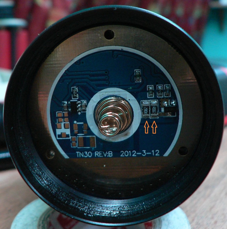
Alex - did you piggyback your 0.12R resistor on one of those 2 shown in the pic? Or just cut it in with wire, laying it along side somewhere. Spasmod is saying there's not enough height space.
I piggy backed it on top log the existing one, I later bought a R082 SMD resistor from Digikey and soldered it instead of the R120, for a little more current to the led.
The digikey part number for the 1206 0.082 ohm SMD resistor I used is P.082AVCT-ND which is 0.75mm tall and does fit with no issues.