Due to time constraints and a busy schedule this years torch build will be short and sweet.
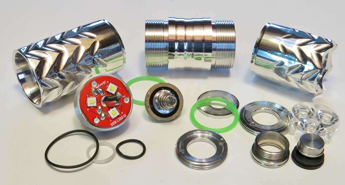
Basically it will be a triple, not sure on leds yet, possible de domed XPG 2 leds or XPL HI, BLF A6 driver, 18350 battery and a Convoy S2+ metal switch.
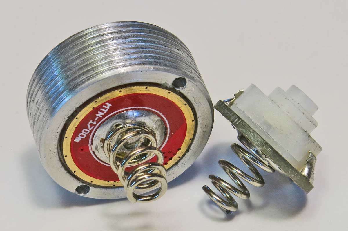
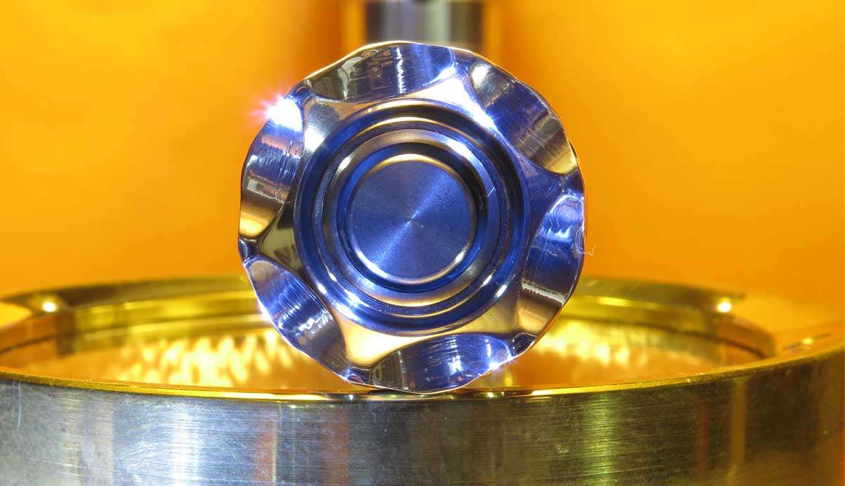
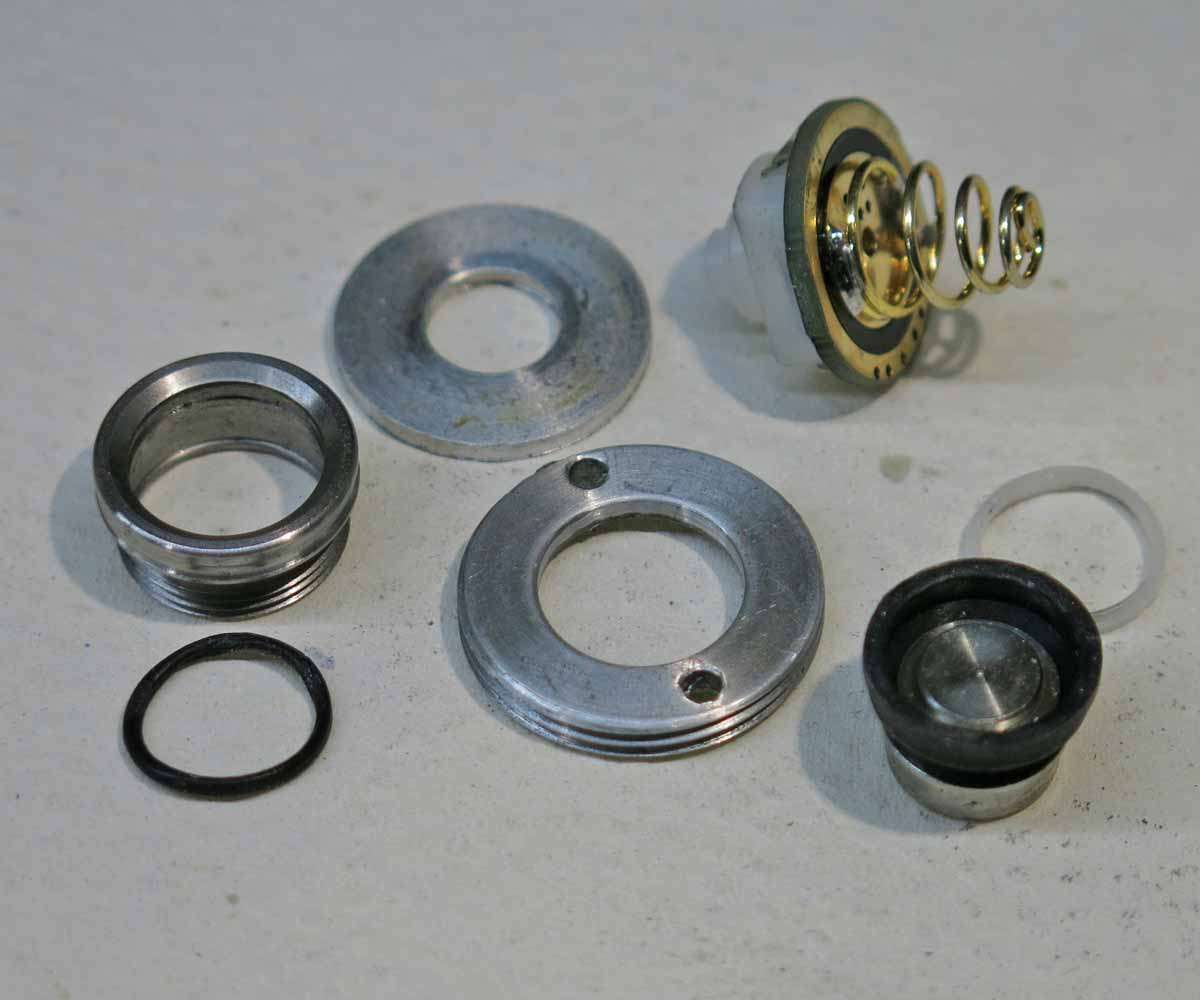
The components from the S2+ switch along with a new threaded adaptor. The spring on the switch will be replaced by a Blue spring. I love utilising items created by other users on this forum into builds or mods.
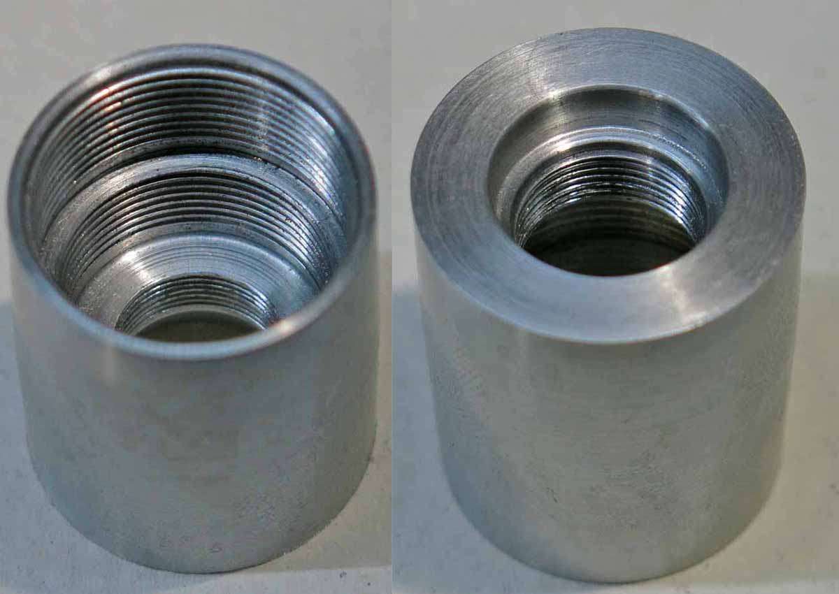
The tailcap. This has three threads rather than the normal two threads. The third thread being the smallest here is for the S2+ switch to screw into.
This picture shows the switch assembled into the tailcap. If you haven’t guessed l love these metal capped switches.
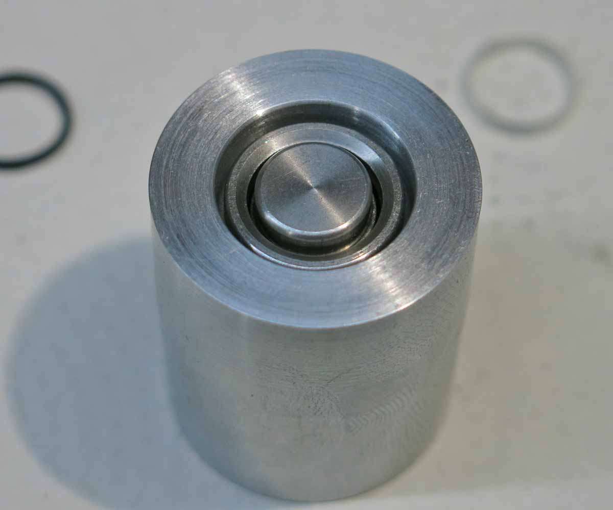
The switch retainer is recessed on one side to centralise the switch board into the tailcap. This threaded collar is held in the chuck in a split bush to allow the recess to be machined.
After awhile lots of split bushes are collected. Its usual to not have one in the size you need.
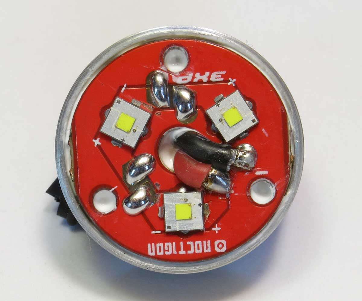
And the switch sitting in its new home.
Threaded mandrels are also made up to hold the torch components, battery tube, head and tailcap, in the lathe chuck so they are not damaged by the jaws and also if the item is tapered on the outside still allows it to be securely held.
Update 14.11.18.
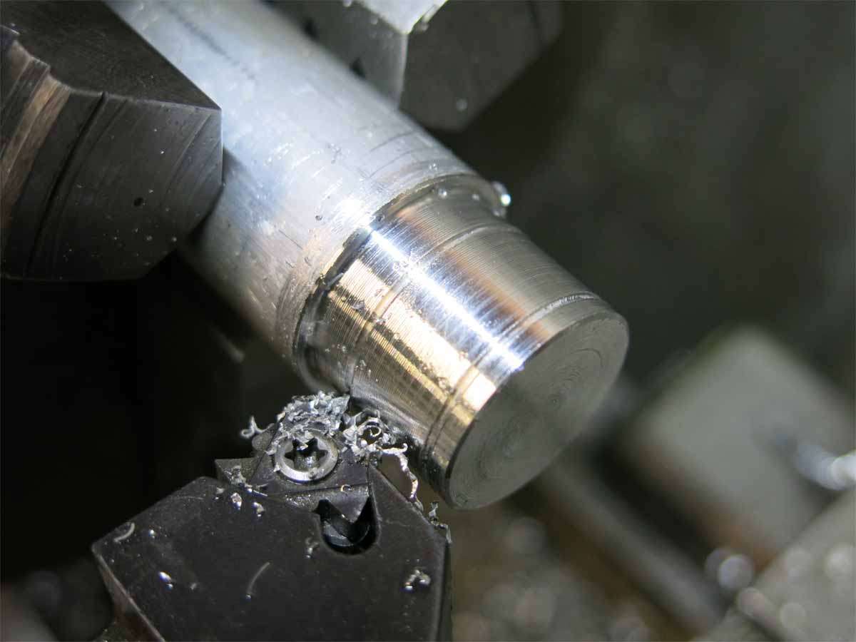
We start of today with the pill and driver retainer. The diameter is turned to size, The grooves cut are for the lead in and out of the thread. The small section is the the driver retainer. the pill itself has an overall length of 10mm.
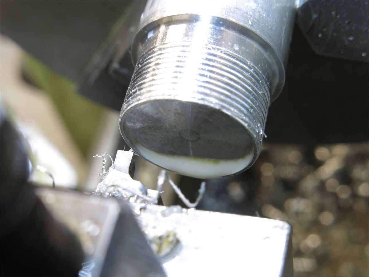
The driver retainer has already been parted off here. The machined recess is for the MCPCB to sit in.
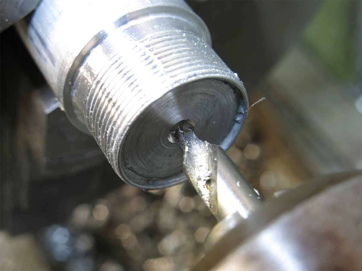
The tool here is called a centre drill. This is used to drill a taper in the end of the work piece so when a hole is drilled it starts on centre. A hole is then drilled for the wiring to go through.
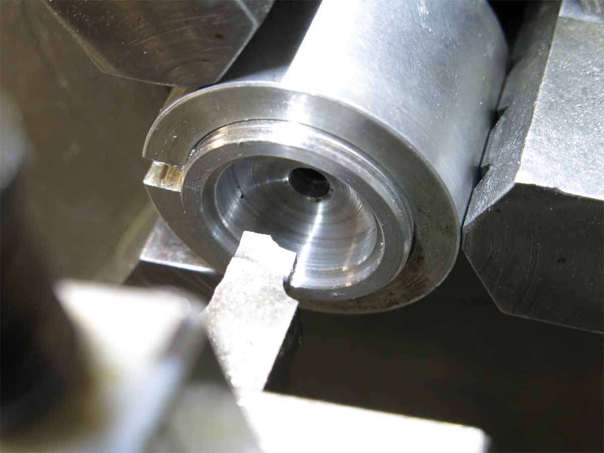
The pill was then parted off and placed in a split bush so the driver pocket could be machined.
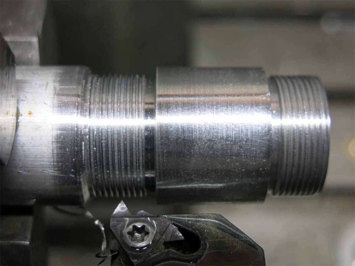
The battery tube outside dimensions were then turned to size. The grooves are for the threading tool to run into.
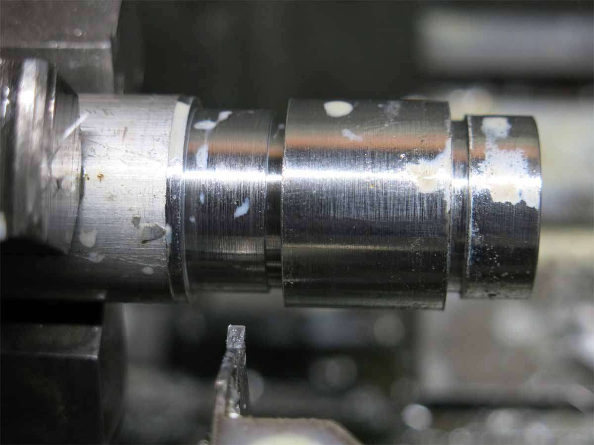
The threads were then cut for the head and tailcap to screw onto.
Update 18.11.18.
Today was a good day and a bad day.
I was not sure on a pattern for the light so played around with a design on a test piece.

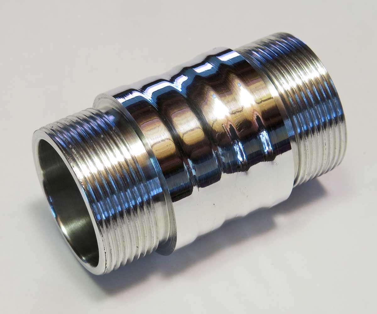
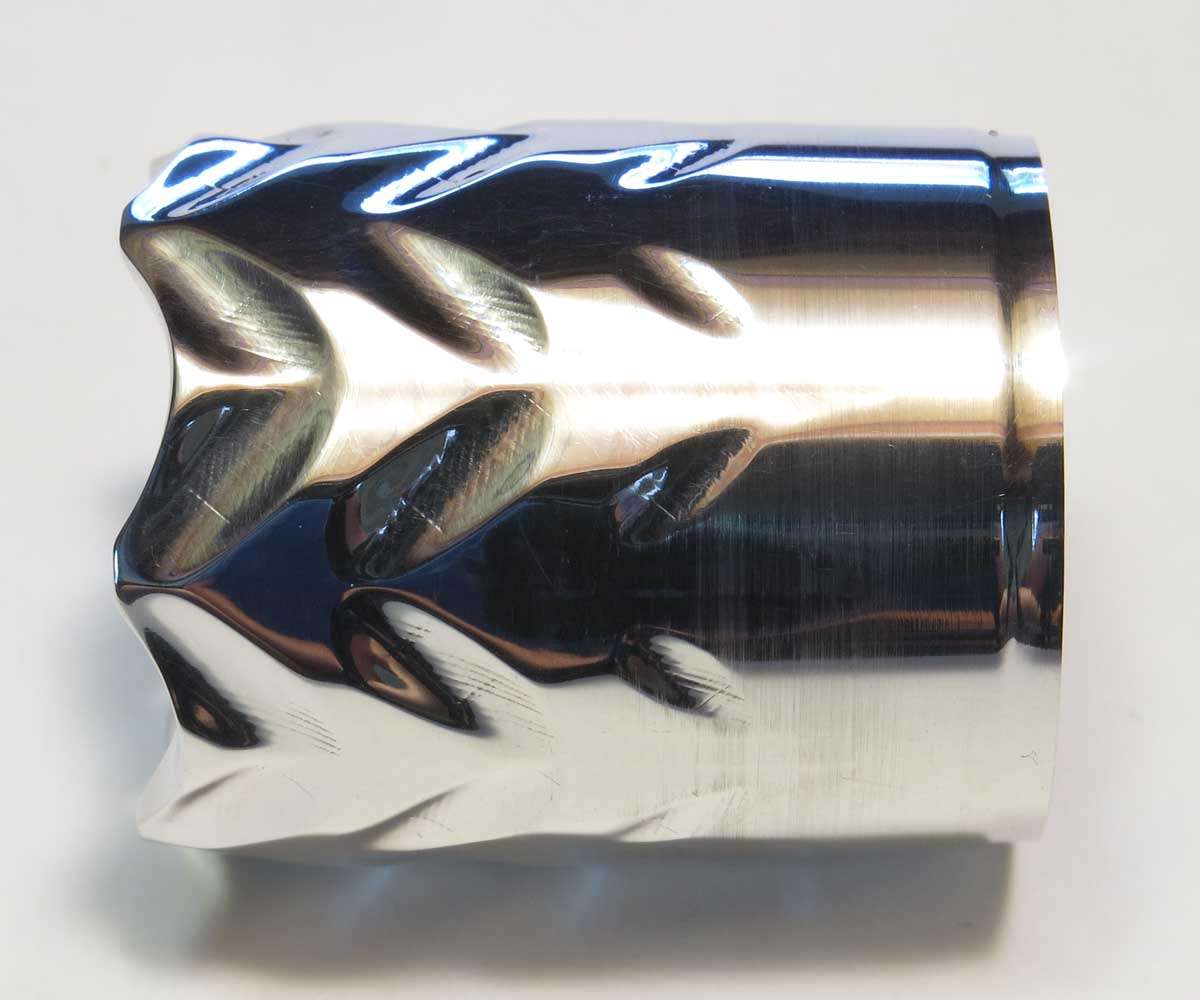
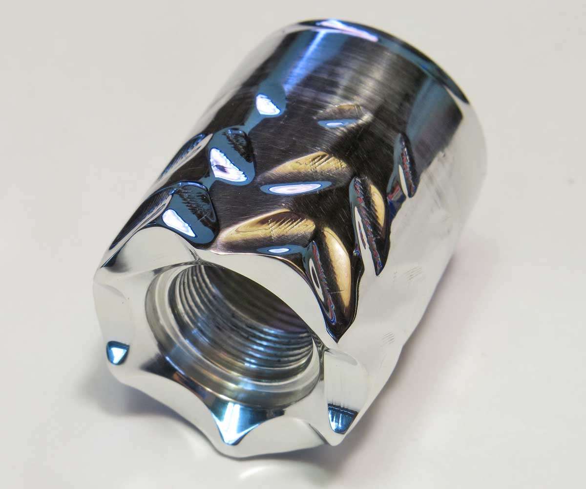
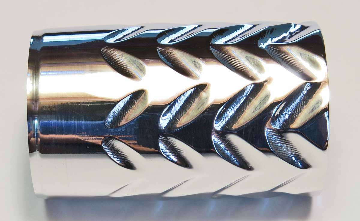
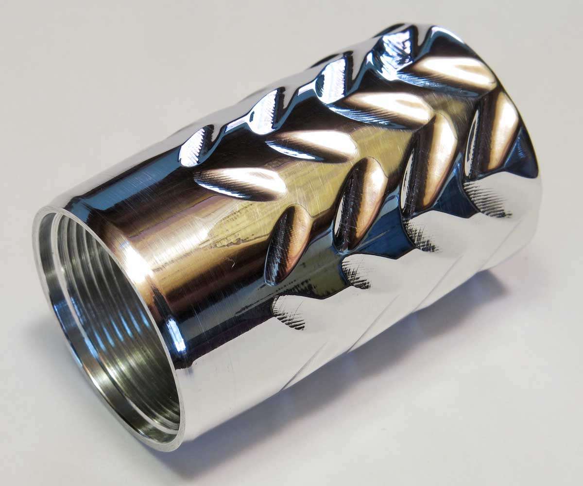
The head and tailcap had 12 flats machined on the largest diameter. These flats were machined .3mm deep. This is the head here.

I had not realised I hadn’t taken any pictures of the head while I was machining the grooves. Possibly because on the angle’s first cut I wound the work piece the wrong way, winding the head into the tool instead of away from it making the groove a lot deeper than planned. Not having time to make a new head I decided to work with what I had. When it came time to machine the grooves opposite the first lot I could not remember the measurement I took as a reference point so took a guess. I’d say the second lot of grooves are about 2mm lower than the first set of grooves. :person_facepalming:
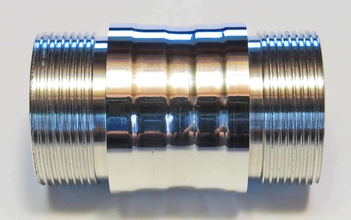
Anyway here is the tailcap after it had been finished being machined.

And finally a couple of pictures showing a couple of tools used on testing and reflowing.
Firstly is the reflow setup. I have been using this set up for a few years now.

And secondly the battery setup used for testing reflows. It consists of a AA battery holder with a AA LiPo battery with a couple of home made prongs that are placed on the + and - on the MCPCB.