MT3608/SX1308 boost converter and others

Free Shipping 5Pcs DC-DC Step Up Power Supply Booster MT3608 Max 2A 2V-24V To 28V Step-up Module For Arduino @ Worldchips

5PCS MT3608 2A DC-DC Step Up Power Apply Module Booster Power Module for Arduino @

excellbay

(10pcs) MT3608 DC-DC 2V-24V Step Up Power Apply Module Booster Module 2A for Arduino @ simitter01

Quite nice boost boards. I've been looking at these lately because of inherent output voltage differences found in powerbank modules which, in practice and due to cable and contact resistances, end up playing a major role in actual output performance. When you receive a powerbank module with a relatively low Vout (like less than 5.1V), you already know that can cause power negotiation issues (lesser charging speed). I've had this issue recently with an inexpensive underperforming powerbank board.

Well, key here is these modules feature their schottky diode at the output, thus they can be carefully tuned to a given voltage and have a fairly decent load balancing when set in parallel. Soo, what do you think? Experiences? Reviews?

2 to 3 (or more) of them should provide a well balanced and powerful 5.2+V output for custom powerbank and/or other power supply requirements with a BMS fitted out 1S li-ion source, seems to me. What do you think?

I have a dozen or so of these in my parts bin that I use for random projects. They do what they say, the 2A current limit may be a bit generous though, they will get very hot running that hard. For a single cell lithium to 5V application 1A to 1.5A continuous output will work fine. Efficiency is in the mid 80% range if I remember right.

I've peeked at a couple of related datasheets (Prom Electric, Olimex). The footprint is quite small and they could be set to operate in parallel with ease, or so I believe. I have to admit I've at times wondered why no one has ever designed an optimized boost-buck driver for single li-ion cells with full cell operational voltage range (2.5V - 4.35V, or thereabouts). An initial boost stage with cell undervoltage protection plus a fully regulated multiple modes buck stage. With a relatively tight boost/buck stage voltage differential, efficiency could still be quite good.

May order a bunch soon.

Hi Barkuti , we meet again in the land of converters ! I used some of these modules for working lights , those with 2S 18650 (8.4 V) , to raise the voltage to around 10-11V , for leds ,10W /12V .

I know , you will say that are not suitable for led driving , having no current limit , but ,in practice , if you set the voltage in such a way that the start current to be 0.9 A , even after 1 hour , the max current will not exceed 1A !!!(the heat sink of these working lights is generous enough...)

Unfortunately ,at every 10-12 pieces ,I had at least 2 module that fried instantly , with the voltage set to minimum , and low load (under 0.5A ). And , as I understood from the feeds back , some customers had the same problem..., could be some rejected items mixed with good ones ( at this price is not a great loss...!).

Using them in parallel should not be a problem , as long as you "pair" them on a bench , for the SAME output voltage , under a moderate load .

For example , I'd paralleled 3 modules CN6009 (boost modules with XL6009 circuit ) , for a 10 amps load (Vin=9V , V out=12V) , with no problems of all !

The only thing is the dissipated power , that should NOT exceed the stated one ( in my case , 10W per module )

About your question ( boost for single Lithium cell ) , these are too edgy , not many of the customers are lights related , so the market will be not profit fitted.

See ya !

Hello!

I've also been playing with some inexpensive XL4005/XL4015 modules recently; right now converting my cheap hair clipper to li-ion power, inserting an XL4015 CC/CV regulator close to the power connector of its custom power supply wire for proper battery recharge.

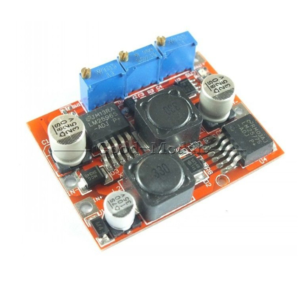
By the way, do you have some links for inexpensive non-LM2577 boost modules with constant current feature? Found plenty with LM2577 and LM2577 + LM2596 boost/buck units, but seems to be some lack of XLSEMI CC/CV designs.

I was looking my self for CC/CV with LM 2577 but , unfortunately , didn't found any...!

Mmm, maybe saying “plenty” was a bit enthusiastic…

Grab some bag:

https://www.aliexpress.com/item/1PC-CC-CV-Voltage-Regulator-Automatic-Boost-Buck-Converter-4-35V-to-1-25-25V-LM2577/32672343981.html

Weird “minimum 7V input” limitation to use constant current mode. Two inductors, single LM2577 and boost-buck?

Oh! Wait! The photo shows an XL6009!!!

Down Boost Buck Module Lm2577s Lm2596s Power Dc-Dc Step Up Voltage Converter @ good-module

Not so bargain already…

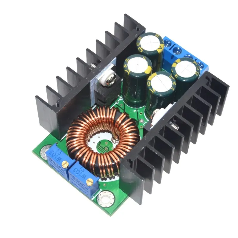
I then have the “250W 10A boost” in my list, but that's a non-LM2577 one you already now.

Hope this helps.

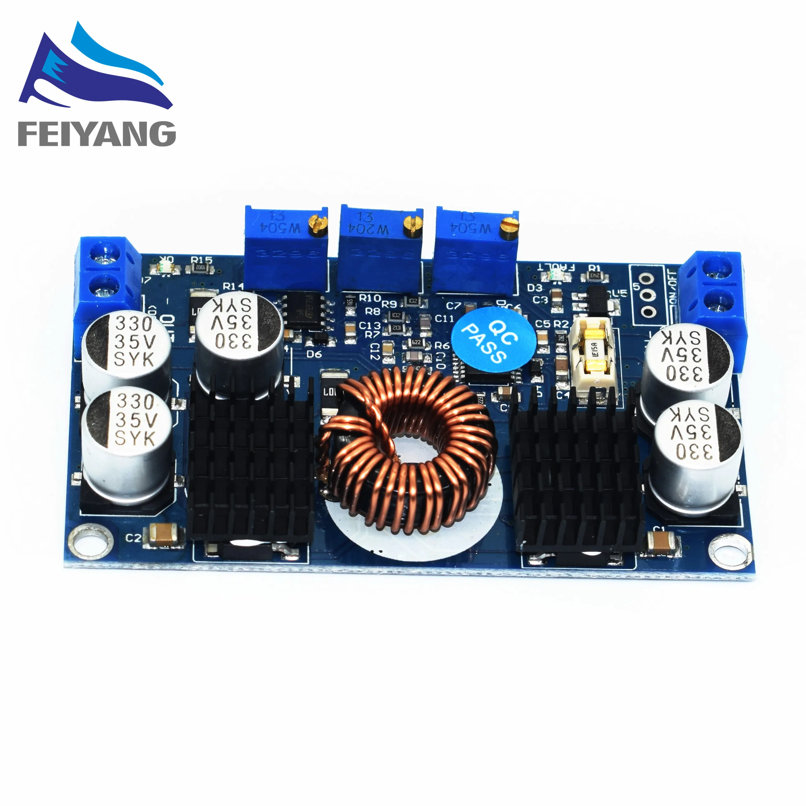
My favorite buck-boost modules are the LTC3780 modules available on ebay and elsewhere. Good current capability and lots of flexibility. They are quite a bit more expensive though, and larger. Depends on what you need for the application at hand.

http://m.ebay.com/itm/LTC3780-Automatic-lifting-pressure-Constant-voltage-step-up-step-down-10A-130W-/111557983282

Basically , LM2577 and XL6009 are same ,with differences of pins arrangement , currents (XL has 4A , LM has 3A ) and internal oscillator (400Khz vs. 52Khz ).

Also , XL6009 has an enable pin , good for start -stop by external signal ... For me , it looks like XL is a better version !

The second module (LM2577 & LM2596 ) is good for charging , I'm using one for charging Lipo ,recovered from different appliances. It is ok . And you're right , the price is...

Thanks for share.., and if a 250W/10A will be on your work bench soon , I have some tips for making this particular converter a real 250W one !!! (at this moment I modified , tested and mount 27 pieces in different led light projectors , for inside and outside purposes , houses ,motels ,museums ...)

Hello! :-D

I was yesterday speaking with a friend which encouraged me a bit into building a flexible battery powered flood light mostly for indoor use, we often go to a small country house with no installed lighting, although it has a mains socket.

In order for the stuff to be sort of pluggable I've thought in going 1S with the cell pack, thus I can use multiple TP4056 boards and even power it up with various 5V chargers in parallel. Target emitter XHP70 in 2S config, I think I can use ≈12x MT3608 boards in parallel to boost the 1S voltage up to ≈8V and then regulate the output current via a dual 10KΩ logarithmic taper potentiometer attached to a pair of (heatsinked) CC/CV XL4005/XL4015 buck modules replacing the onboard current control trimpots. Heatsink would be massive and the setup should handle 6+A continuous to the emitter with ease. I would handle battery protection via a couple of 1S BMS circuits whose MOSFETs I can control by a switch in between the boards' P+ and the battery anode, which is an elegant power switch I believe.

Enough for now.

Cheers ^:)

Hello! Anyone watching this?

Been thinking about this for a while. 3S battery configuration feeding the XL4015/XL4005 buck modules is certainly better with regards to efficiency. Problem is, I am not really sure if these modules will happily work in parallel:

Any of you know better?

Cheers ^:)

They should work well in parallel in CC mode, I wouldn’t trust them in CV mode. I also wouldn’t want to parallel the MT3608 modules, getting their voltages all set to the same value and having them not drift would be near impossible. Why not just a 1S input into a bigger CC boost converter?

Right now I have two spare modules of that kind whose only differences are the different shape of their SK54 diodes and their onboard chip models (one 4015, the other 4005). With both of them heatsinked, in parallel, and this A10K pot instead of their CC trimpots the stuff should shine bright.

I also looked at the possibility of using a proper 1S boost driver, but couldn't find an inexpensive and adequate 6+A solution. H1-A and H2-C drivers aren't cheap and can't really go that high in power output unless you use a couple in parallel, and commercial boost modules do not work in CC mode at 1S input voltages.

Thanks for the tip with regards to the MT3608 modules, however at least they should do nice working in parallel to boost 5V to ≈13V for battery charging. How about two female USB micro-B inputs with two in parallel MT3608 boards each? It would only be 4 boards and they have diodes right at the output, should work well I believe.

Not sure if I'll dip into this, we'll see.

Cheers ^:)

Dear Barcuti ,

As I told you some time ago , ANY boost converters COULD be set in parallel ( but no more than 2!...). I 'm doing this for few years now , and I NEVER had problems...The idea is to set the output voltage at THE SAME VALUE, up to the second decimal , the thermal drift of voltage will be negligible ...The current set to 1/2 of the max value ,and you are good to go... Dummy load for each converter, for the accuracy of settings...

For the case that you are a perfectionist (!!!) , you can insert , on the output , two schottky diodes ( able to sustain the current demanded ) , one for each converter .., in this way , none of the converters will be a load for the other , even in the case that the difference in output will became significant...

As I know that you are a professional , testing on the bench wouldn't be a problem !

I remember that once I forgot to set the current potentiometers at the same value ,on both converters , and guess what...nothing happened , because in the moment when one converter reached the maximum set value , the voltage slightly drop ( maybe 0.1 V !) , and the other one started to take over the load...

Hi cera@1967, what's up? ;-)

I also took a peek at the popular generic CC/CV XL4016 module sold nearly everywhere, though I heard it has some :???: glitches.

I'll definitively end up going 2x XL4015/XL4005 in parallel if anything. Good to know they work well in tandem. Besides, I love logarithmic potentiometers for this stuff.

The MT3608 units should work nicely in parallel, each module features a schottky diode right at the output.

Cheers

https://www.aliexpress.com/item/1PCS-SAMIORE-ROBOT-LTC3780-DC-DC-5-32V-to-1V-30V-10A-Automatic-Step-Up-Down/32834139255.html

Price seems to somewhat have gone down for these converters, nice.

Jensen567 commented about 'em in #8. Can these modules operate in continuous current mode at the minimum specified input voltage? Wonder how really good and efficient they are.

Hello! :-))

Small update in this regard.

Mmm, maybe that issue is related to what is described here: https://www.instructables.com/community/Why-is-my-step-up-converter-not-boosting-voltage/

So these small boards feature a design slip-up.

Hope this is of help.

:-)

Maybe anyone here can help me. I’ve made a little lantern using 12v led strips powered by a xl6009 based boost converter and a single 18650. The problem is: it just doesn’t deliver enough current. When I turn the regulator screw, the brightness goes to a lets say mid-level, and if I keep screwing it goes low. And more, if I set to mid and turn off, when I turn on, it’s low .
I’ve tested using 2s, and it works just fine.
Do you think that 1s is too low for 12v output, or it’s a defective converter?

With the limited amount of information provided, all I can say is that it is very likely that you are surpassing the converter's limits for some reason.

When feeding the converter with 1S cells instead of 2S, you force it to draw twice the current (versus 2S). Also, power losses in conductors and contacts increase as the current flow increases (P = V × I = I² × R), while at the same time and for this reason the actual useable input voltage to the converter gets reduced further. For it to have better chances to work with just 1S cell, consider the amount of current draw you may be forcing it to draw: for 12V output with 1S cells input, due to conversion efficiency losses input current will in practice be no less than close to 4x the output current. You may also need to optimize the (input) current flow path: cell(s) soldered or spot welded, lower resistance contacts, etc.

Also, you don't say what “XL6009 boost converter” you are using. You also speak of “the regulator screw” which actually means that you are turning some single :???: onboard trimmer, doesn't it? Or does it feature two regulator screws / two trimmers? Trimmers are not meant to be used frequently. If you need it so, better swap the trimmer with a potentiometer. If not, its lifespan could be rather sort.

So, as I say in the first place better provide a link and/or picture of the module you speak of; it'll also be of great help to other contributors here.

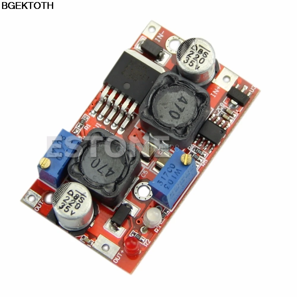
Thanks for answering. The regulator module looks like this one, except the inductor, that on mine is 470 instead of 330.
I don’t have a multimeter here, but I think I’m getting less than 0.5W when turn on with full load and 1.5W adding load after turning on. On 2s I can easily get around 10W.
So that’s the name, trimmer. Well, I certainly have managed to do more than 200 turns on this thing trying to understand what is going on.