Wow, this is really cool. :bigsmile:
I know... I should do better!!! Ha!  Dan.
Dan.
I don't see a broken drill.... ?? All I see is shiny nice work...where did you break a drill?? Shame!! That's a dock in pay and 10 points on your insurance!!! Dan.
Look at the pill, 4 holes drilled…the top one broke the bit, I’m assuming that’s when the 2 outer ones got drilled.
Question…what do y’all think about this as an option where the reflector makes contact with the soldered leads on the pill…
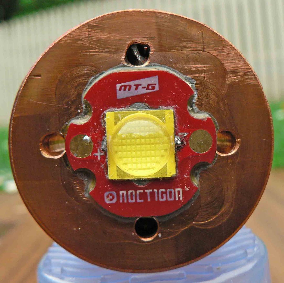
see how MRsDNF has the hole for the wire lead right next to the pad? What if you used a larger diameter wire, say a 20ga or 18 ga, and cut it off square…don’t strip any of the insulation off. Use a short piece of copper or brass sheet and solder it from the pad to the top of the wire like a bridge. Then the wire wouldn’t be on top of the pcb, there wouldn’t be a solder bump, and the reflector simply could not touch the contacts as long as a centering ring was used. Wouldn’t matter if the reflector was square cut on bottom, it’d be raised in perspective to the plane of the pcb face and the sheet material used to bridge wouldn’t be anywhere near thick enough for it to cause issues. A simple donut cut from shrink wrap would be sufficient to cover the pads if a centering ring isn’t used.
Yeah? No bending or twisting to try to get the wire in just the right place to fit the outside of the pad, no worries. Simple, right?
Well... somehow I can recognize that!! Ha! It looks like I worked in his shop!!! I HATE COPPER! The danged stuff is like working with bubble gum...and it wants to grab every tool that gets close! I use it... but that doesn't mean I have to like it!
I use only Tellurium Copper...but it is sure high $$. Take expensive copper X 2 and that's about what it cost. BUT... if you figure the lack of broken tools and spoiled parts it cost about the same I guess. Thanks for finding the bit... now I can give him fits!!!
Dan.
You can get close to that thin with regular stranded wire. I cut the insulation back far enough that there's no insulation on top of the star, tin the wire, then bend it 90*. When soldering I leave the iron pressing the wire, then flatten it with a small screwdriver, then remove the iron and keep the screwdriver in place until it freezes. It flattens out maybe more than you'd think.
Do you solder the wires before the star goes in the pill?
I solder onto the star last, in order to keep the wires as short as possible. So I mount the driver with the leads running up through the pill, then solder pre-cut and tinned leads down inside the pill, if that’s the kind of set-up it is. Lately I’ve done the 1” copper or aluminum solid pill with the star sitting on top and then it’s not an issue as the pads are out in the open.
Yeah I solder to the star last but with the driver not mounted, hanging free under the pill. Moving the driver around by hand to position the wires is easier most times than trying to hold the wire up top with tweezers.
This one wasn't flattened intentionally, but you can see what I mean about having no insulation above the surface of the star. It would be easily no thicker than the .030" insulator if flattened while the solder was still molten.

More...


Beautiful light. Very nice!
Like this in post#81?
Well, yes and no FmC…in that instance the wires are still extending up and out, the “trace” just extends out to meet them. I was thinking of using a larger than normal wire, square cut with the trace piece soldered in a 90degree on top of it such that the wire came up flush with the surface of the pcb, then the trace simply bridged over to the contact pad. Flat, barely higher than a trace on the pcb. Much flatter than a squashed soldered wire. If all the strands of a single wire can be pressed into a single layer and fit onto the pad, then I guess that would be fairly flat as well. I’d worry more about a short or wire breakage with the wire bent at a 90.
I actually thought about removing material from the backside of the pcb to bring the wire up from under the solder pad, even drilling a 22ga diameter hole through the pad. Have the insulation protecting the wire from shorting against the copper pcb base, solder the wire as a flush component on the solder pad to fill the drilled hole. No bump, no bends. That would pretty much take an end mill bit to get a flat cut up to the copper trace of the pad. Tricky, for sure. If it was made that way to begin with it’d be a piece of cake. A hole in the copper, with the dielectric layer covering it and the trace overlapping it, with a wire gauge hole in the trace. That’d be pretty slick. Like a via. Poke the wire through, solder it, snip it off flush. Could that be done?
Thanks again for the comments. About soldering the wires to the contact board I was going to flatten the wires as best as possible and machine some sort of isolator up which hopefully wont melt as the hole in the reflector is pretty big.
More pictures added to the 1st post.
Seeing that light form the front, and compared to the others.. WOOOOW, just WOOW!
Night shots added. light completed for now.
I love the beam pattern! It is a thrower 
In my opinion 6-7 A is ideal for the MT-G2, even when welll heatsinked like this light. You get 80% of the maximum output, which is great, with no extreme stress on all electrical components and connections.
With 12 volts from the bench power supply the led was getting from memory 7 amps.
Real shame the driver wasn’t any good.
I think it’s time to convert the battery tube to 2s-2p using 26650s and drive that led at the proper 9amps with some 7135s!
The light deserves it 8)