Brief Introduction
When design a mid-output range flashlight(means give you 18000-23000lm) Most of manufacturers have to use multiple small LEDs with multi LED reflector to get more lumens.
After a bit of time, A LED Fab name ChangDa finally make some large size single package LED for decent lumens.But their product did not have very high efficiency and the package quality has a lot of problem.
In 2024, CREE released their new product called XFL-10K with 24 55mil size die. But It’s efficiency is extremely low(7.1V*32A=228W only give 16500lm, whhhhhhhat???) and the Vf means this operating point is nearly saturated with no more overdrive possibility. That’s the reason why I contact with a fab to make my own LEDs.
Choosing the best chip/package
Currently in Chinese market, most multi-die LEDs were using San’ An’s LED chips and combined small size dies to a large LES. Here is the four type they often use:
- 43mil dies:high density dies with high efficacy and extremely low Vf
- 55mil dies(like SFP55):relative high density dies with midium Vf and efficacy
- 60mil dies: high efficiency dies with relative low Vf but lower density.
- 75mil dies: low density dies.
Seems our LED has 3V Version traget to Direct-drive market, we want the LED has extremely low Vf to get more current and much easier to drive. So we decide to use 43mil Dies to construct the LES.
Than the next problem is, How much dies we need to use? To answer this question, we have three limitation in below:
-
the die count must can be divided by 2 for 6V Versions.
-
the die count must be the square root of a certain number in order to produce a square emitting surface
-
the die count must less than 40
So we have only two choices which is 16 and 36. But 16dies there were a existing product called SFH43 and only give me 10K lumens max. that’s to small for my expectation. So I choose 36 dies and I made the 3D model for the LED and it looks like this:
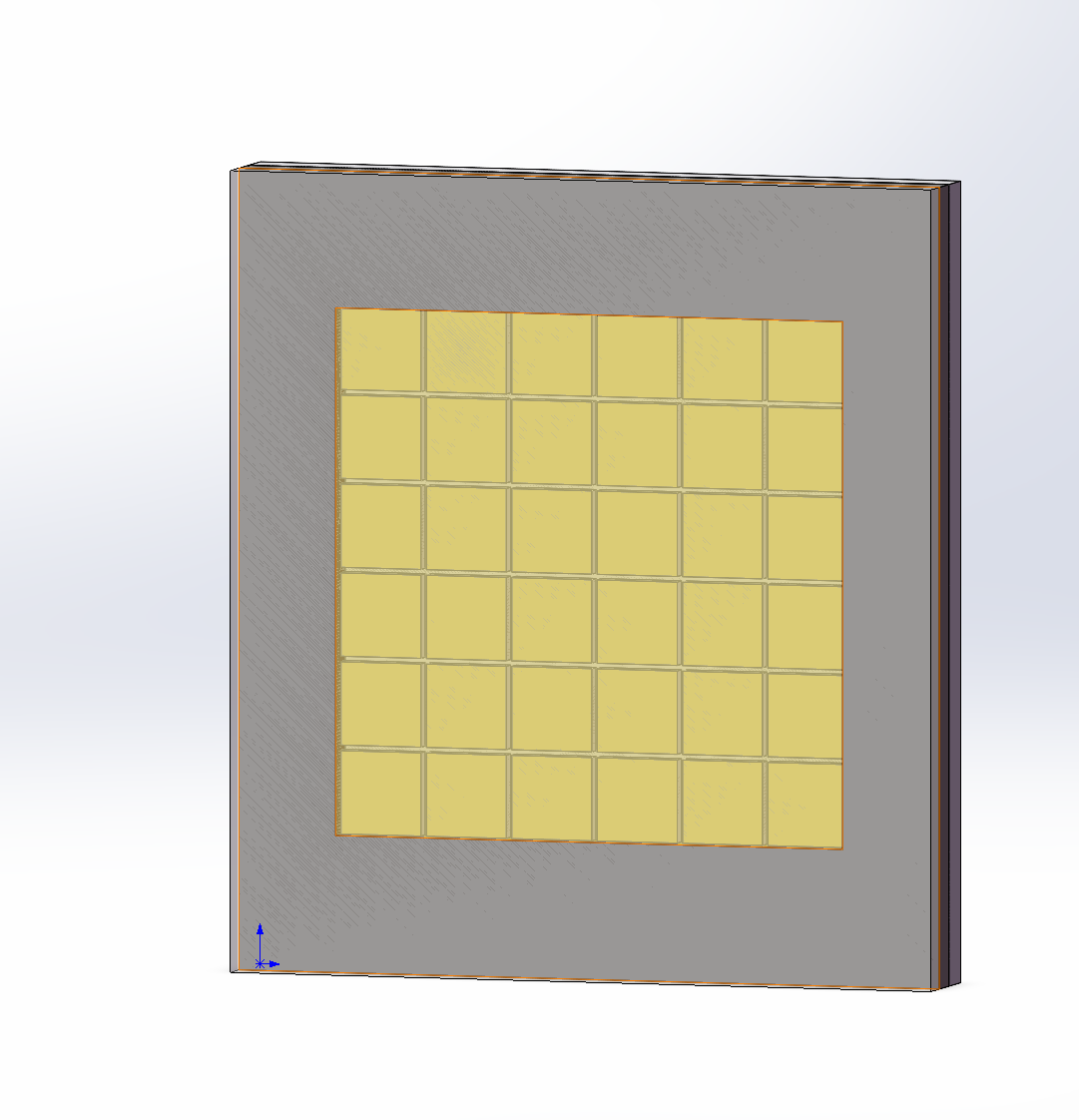
After determine how much chip that we want to use,the next step is design the chip layout and footprint. here is the chip layout and footprint of 3V version:
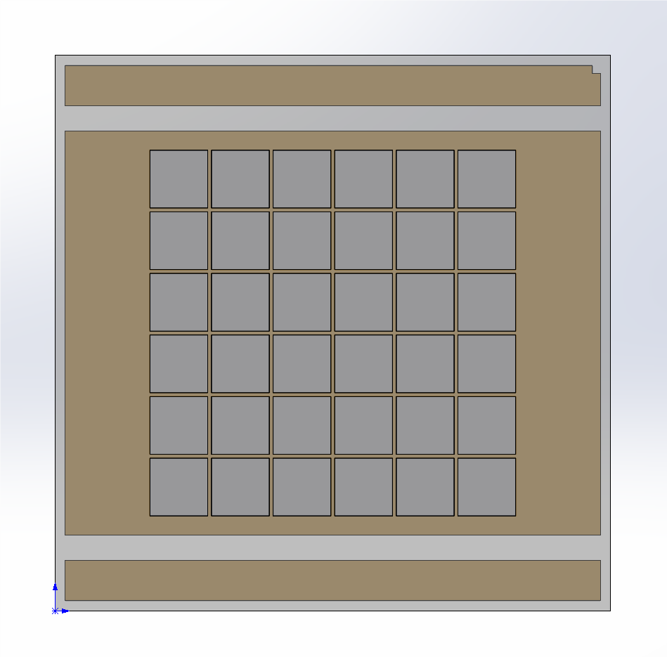
the 3V version will target to direct-drive market so we want to reduce the ESR and thermal resistance of the package. So we use 11x11mm package for larger electrical and thermal pad.
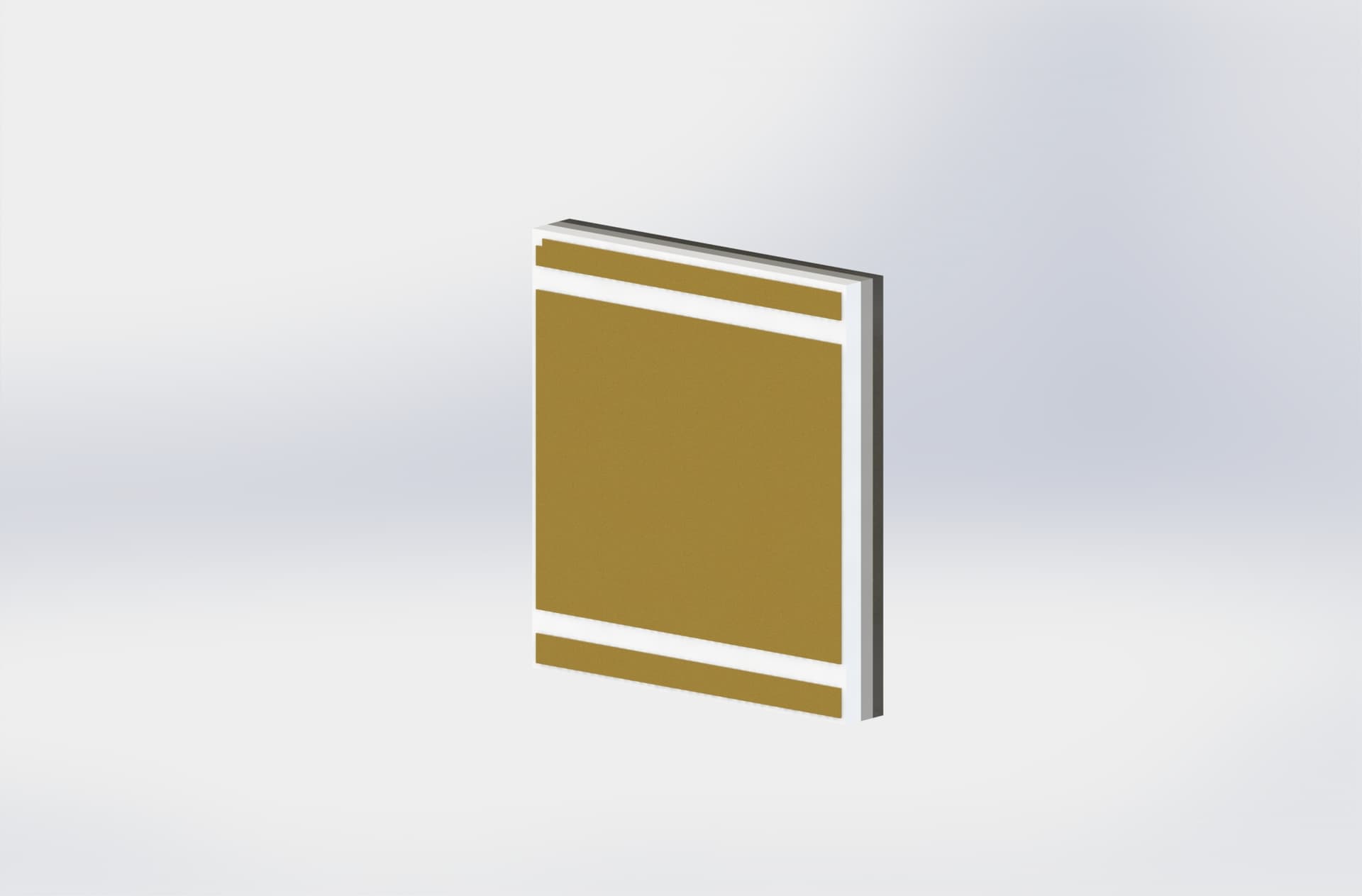
And here is the chip layout and footprint for the 6V version:
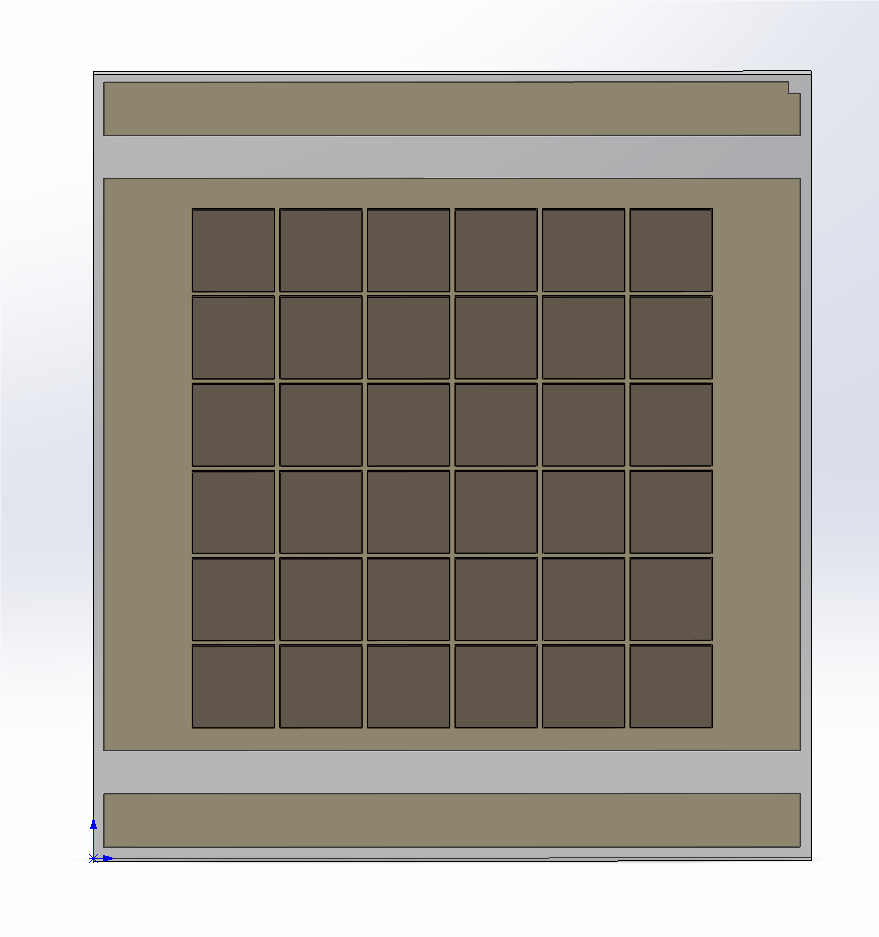
the 6V version is a little bit smaller at the same size as SBT90 Gen2(10x11mm). but in order to reduce thermal resistance so I extend the thermal pad size and make this LED did not compatible with SBT 90 Gen 2.
One extremely important rule when design a custom LED is making sure all the chip are located inside the range of thermal pad and not exceeding the edge of thermal pad! otherwise the chip will overheat(the ceramic substrate only have good thermal conductivity at vertical direction) and reduce the performance of the entire package
Manufacturing process
After choosing the chip technology and layout. The next step is choosing the substrate, CCT, CRI and the method of applying Phosphor. Here is the parameter we choose:
- substrate: Aluminum nitride ceramics
- CCT: 5700K ± 500K
- CRI: Typ. 70
- Phosphor: Coating directly to die.
- PAD finish: Copper with Au Plated.
Because this LED is not for photography, So CRI is not important and we want extreme efficacy for high performance that’s why we choose 70CRI.
When talk to the Phosphor layer, there were two choices:
-
Phosphor film(Mix the fluorescent powder in the form of a suspension into the encapsulated silicone and apply it to the surface of the chip, Called “贴膜” in Chinese): Lower cost but the Phosphor/silicon layer can get extremely hot and burnt for high power density application.
-
Spray coting method(Spray fluorescent powder directly onto the surface of the chip,Called “喷粉” in Chinese):High cost but stronger heat dissipation ability of the fluorescent layer, suitable for high-power density applications.
Beacuse this LED is meant for high power density with up to 6.375W/mm2, For long term reliability, we chose Spray coating process for lower thermal attenuation of fluorescent powder and avoid overheat quenching of fluorescent powder.
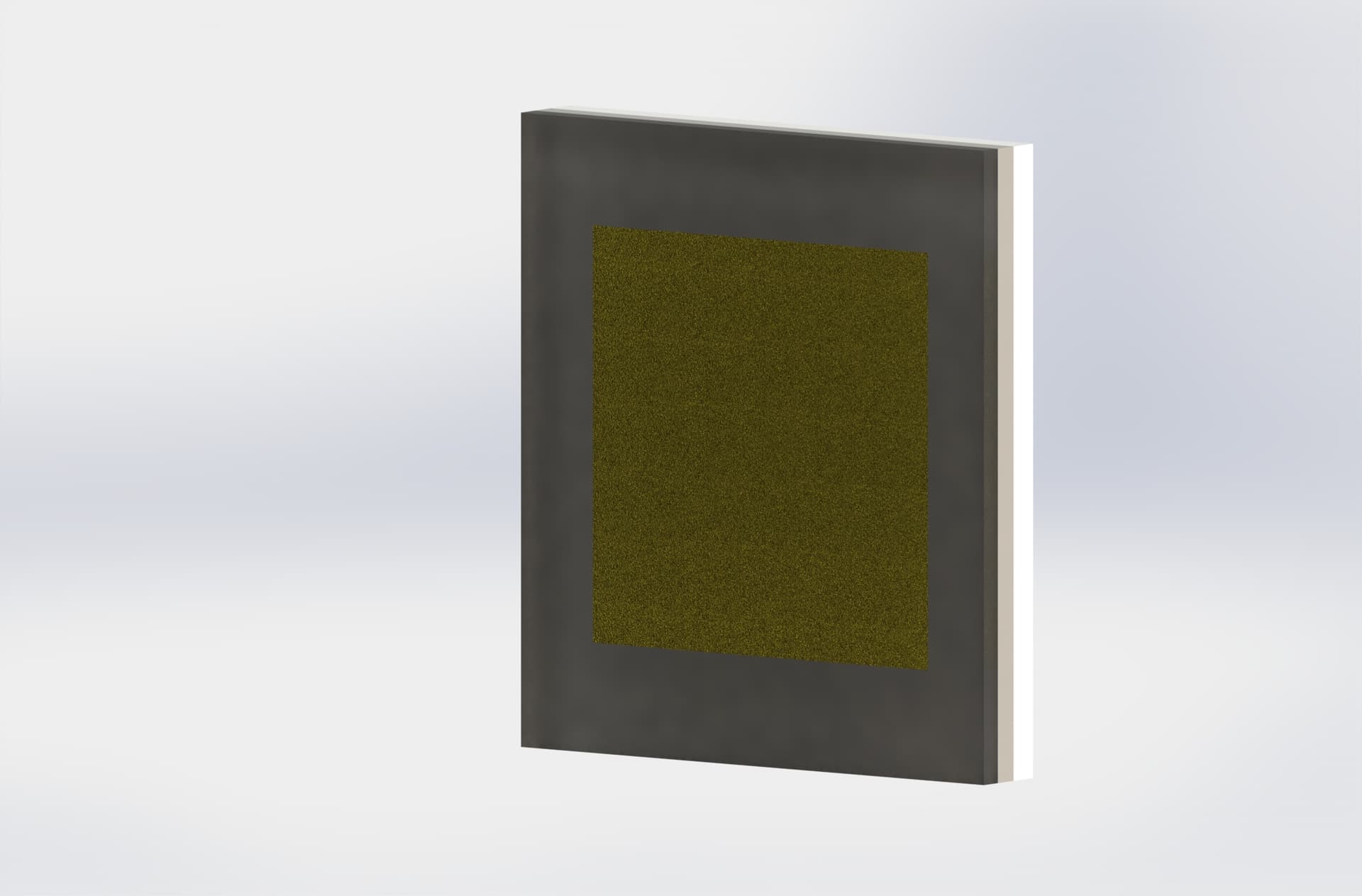
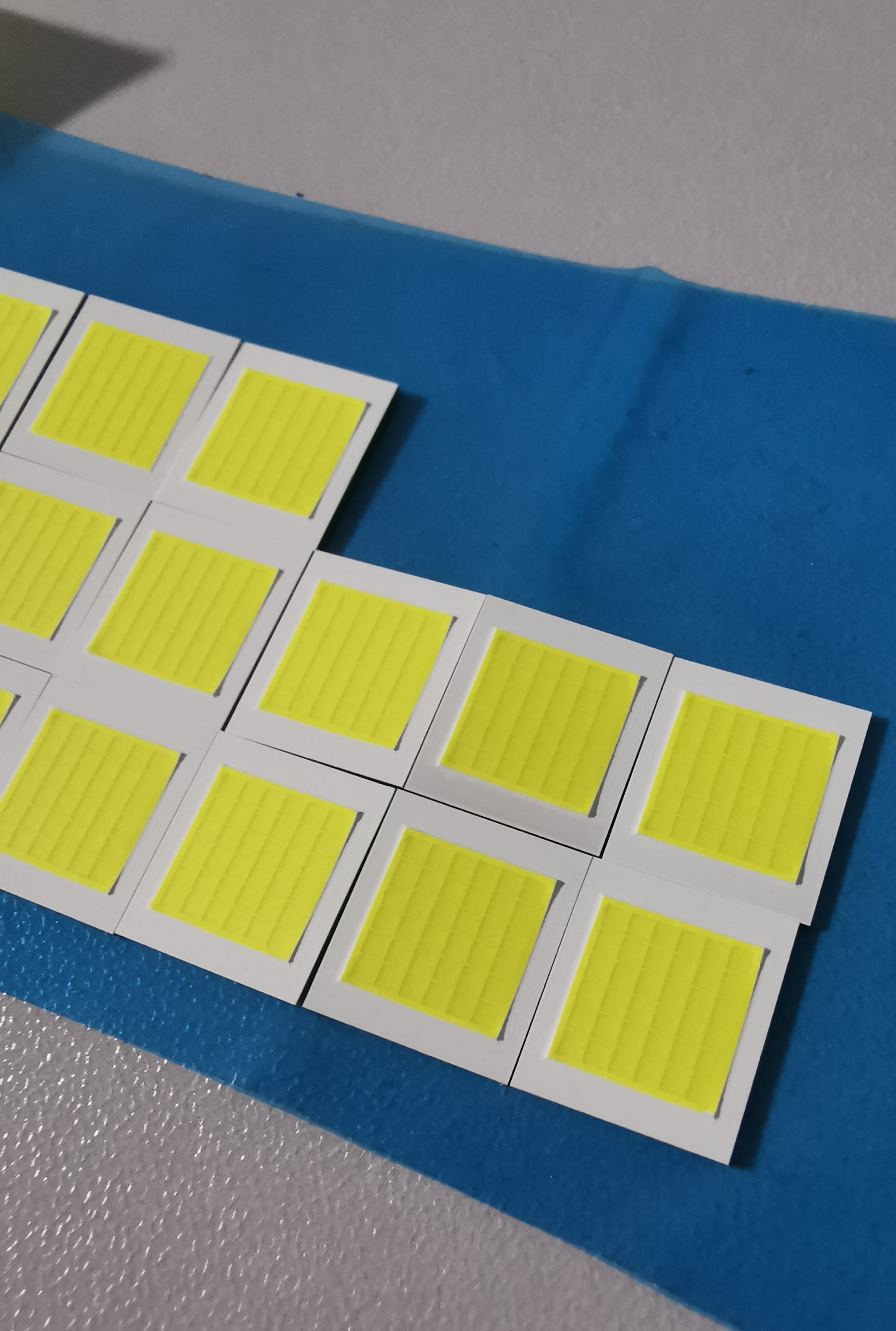
After determining all the parameters of the LED, a contract can be signed to allow the manufacturer to start manufacturing the ceramic substrate made of aluminum nitride material and complete the eutectic process. Here is the Substrate after the eutectic process.
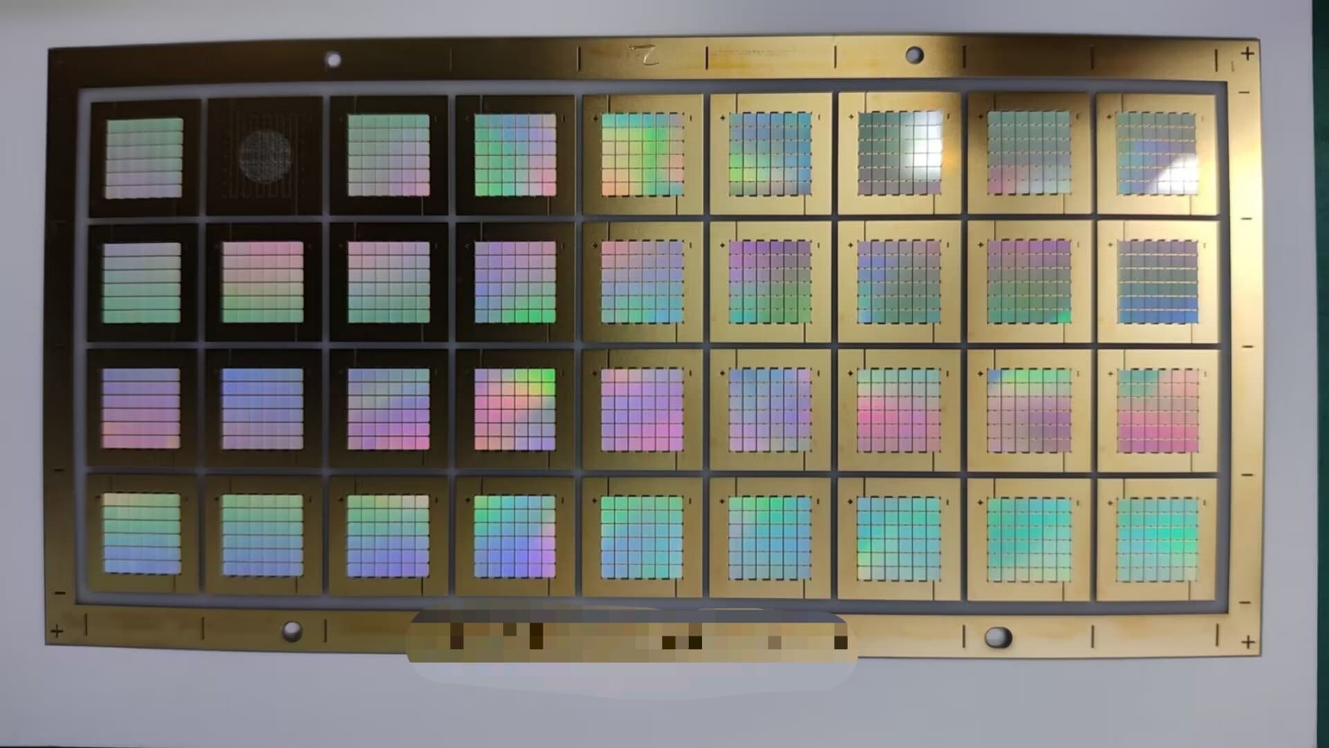

And you can see the colorful 43mil dies which bond to the substrate using Gold tin eutectic inversion process.
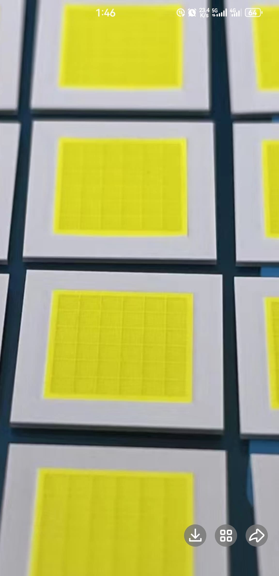
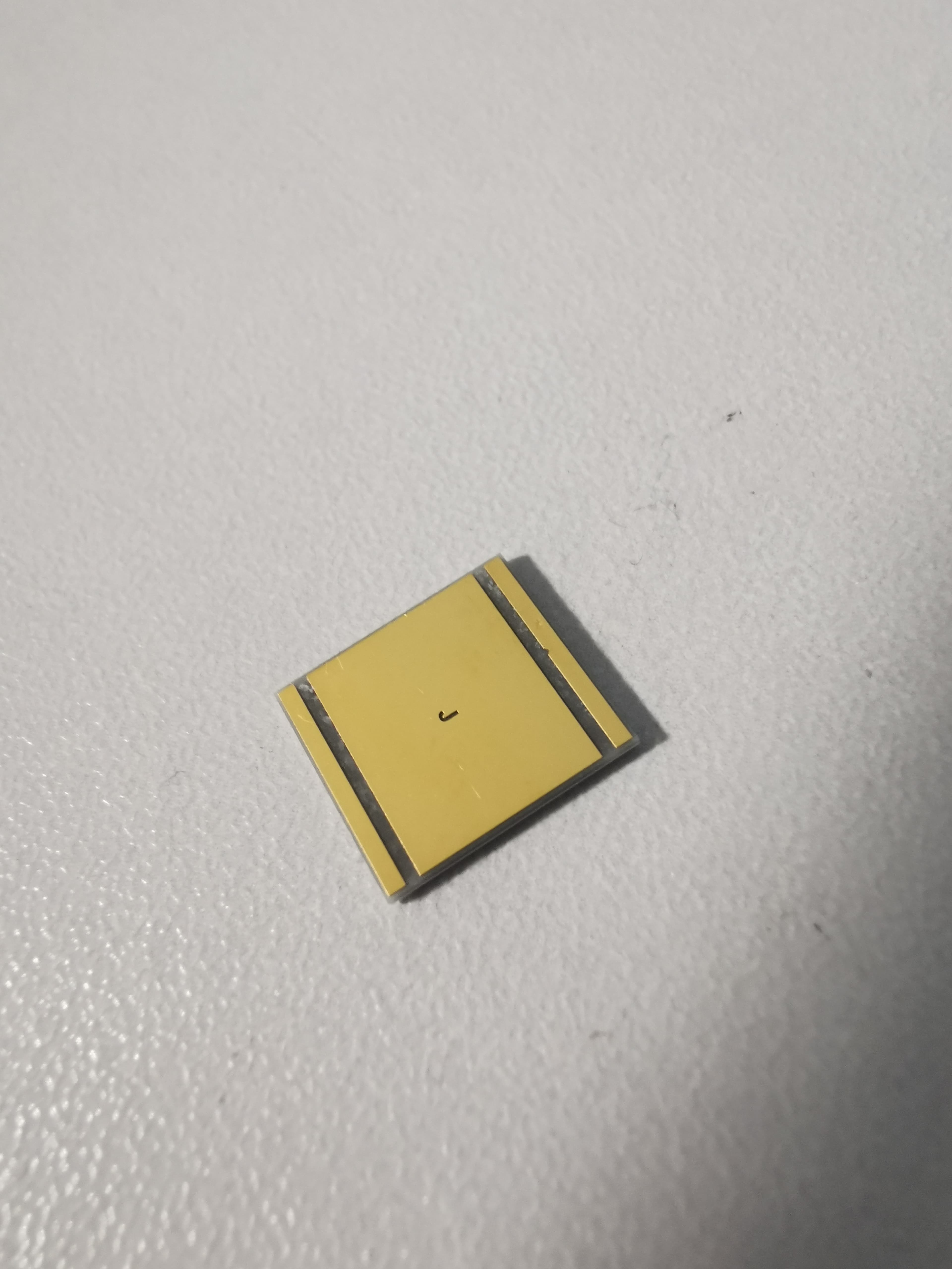
After eutectic process, than the next step is just apply phosphor, protective silicon and separate the LED into single package like this:
Custom DTP MCPCB
Due to the proprietary footprint of FI1048D(with larger thermal pad)means you can’t directly solder it into a MCPCB designed for SBT90 Gen 2. If you do that their will be a dead short between the power lead of the LED and make it useless. So I design a set of Custom MCPCB for this LED.
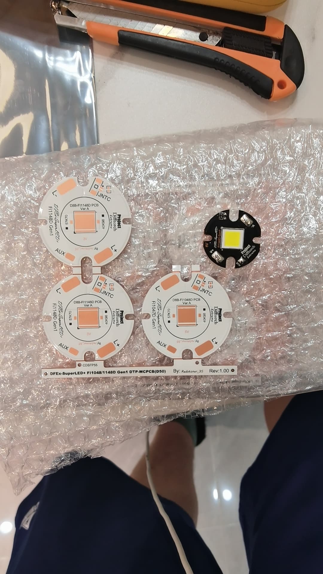
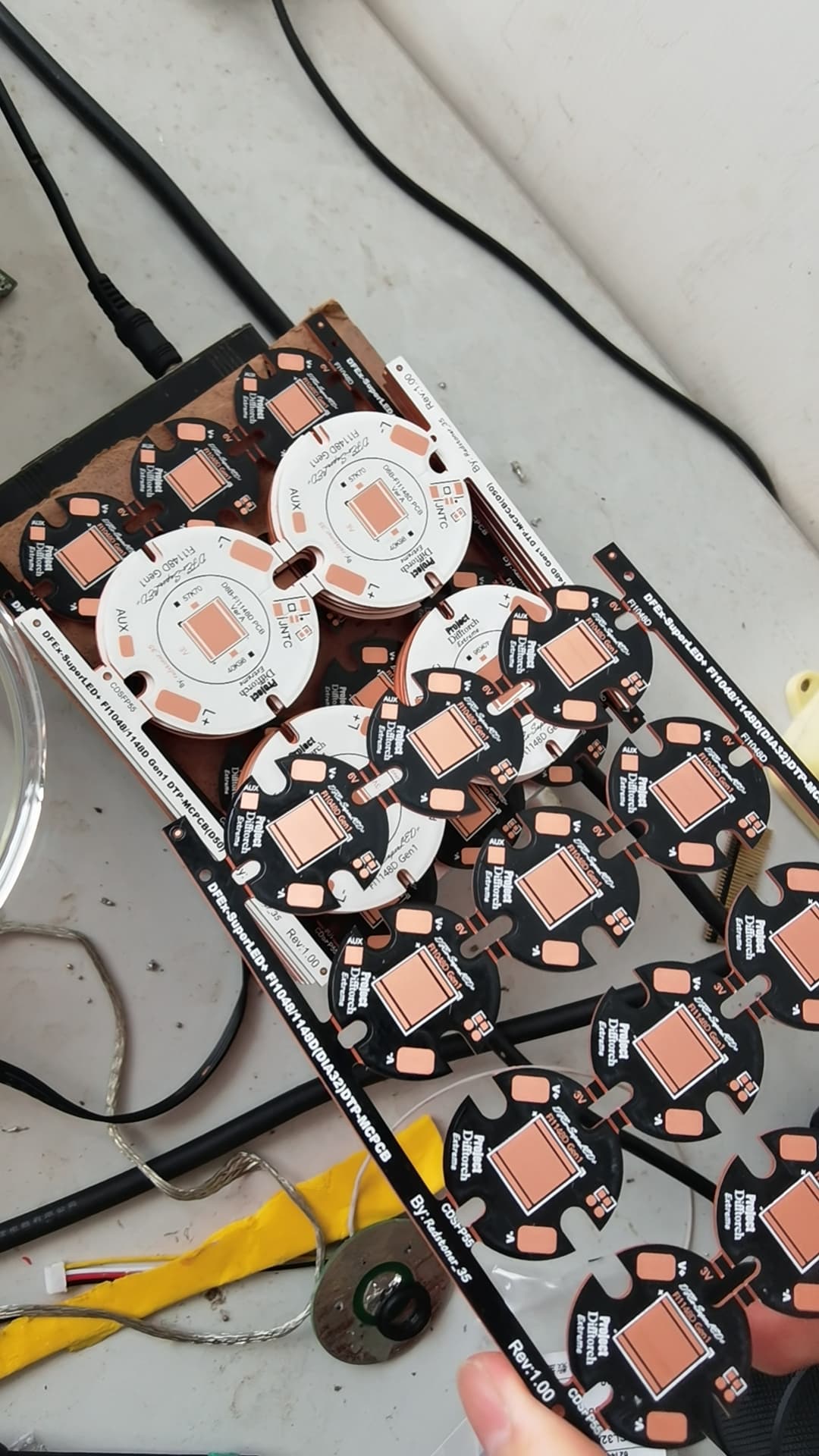
The larger one is a 50mm diameter MCPCB with 4Oz copper for much lower power-loss and target for high power overdrive application.
The smaller one is a 2Oz MCPCB with 32mm diameter for lower power(<30A) entry-level application.
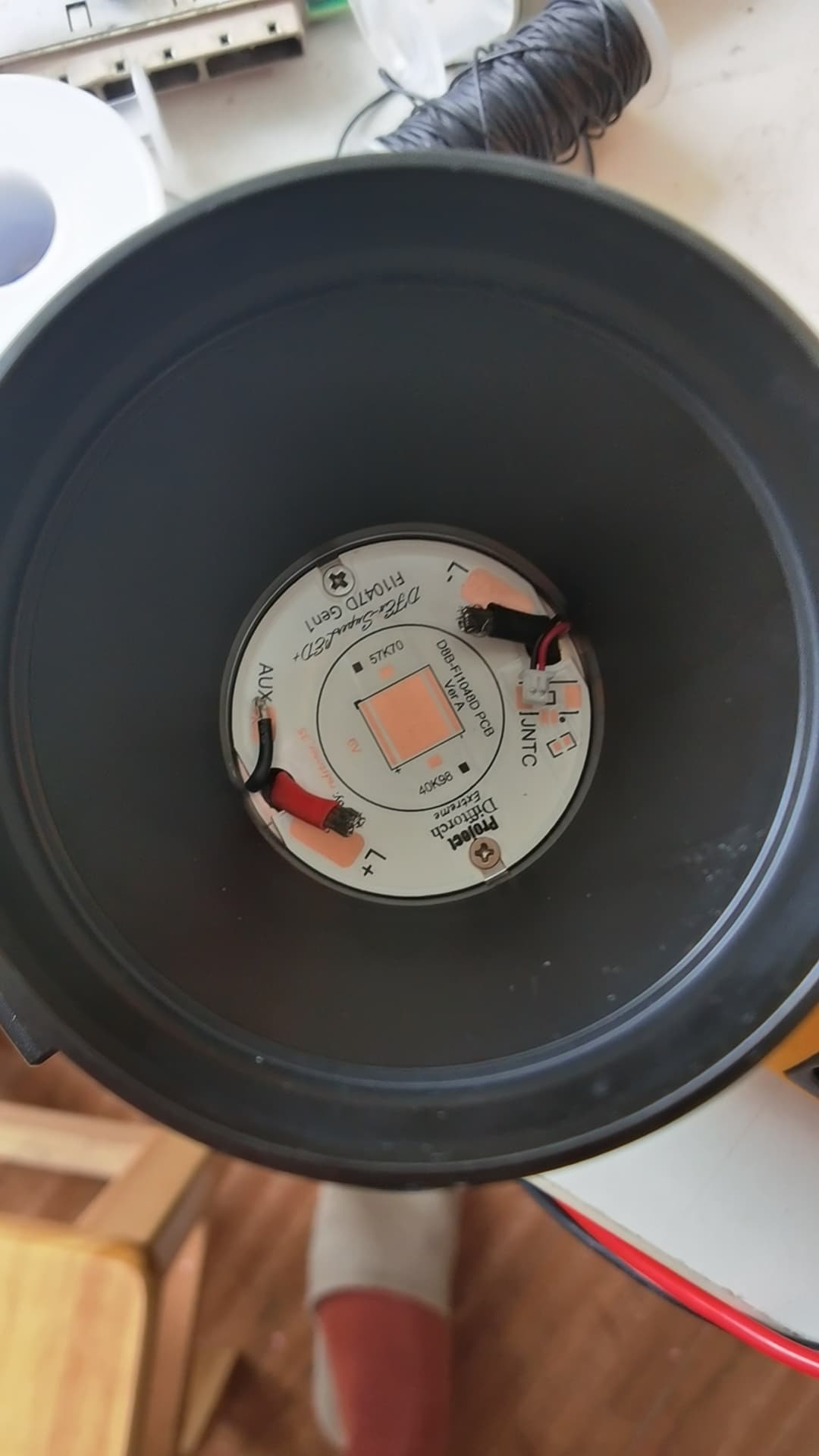
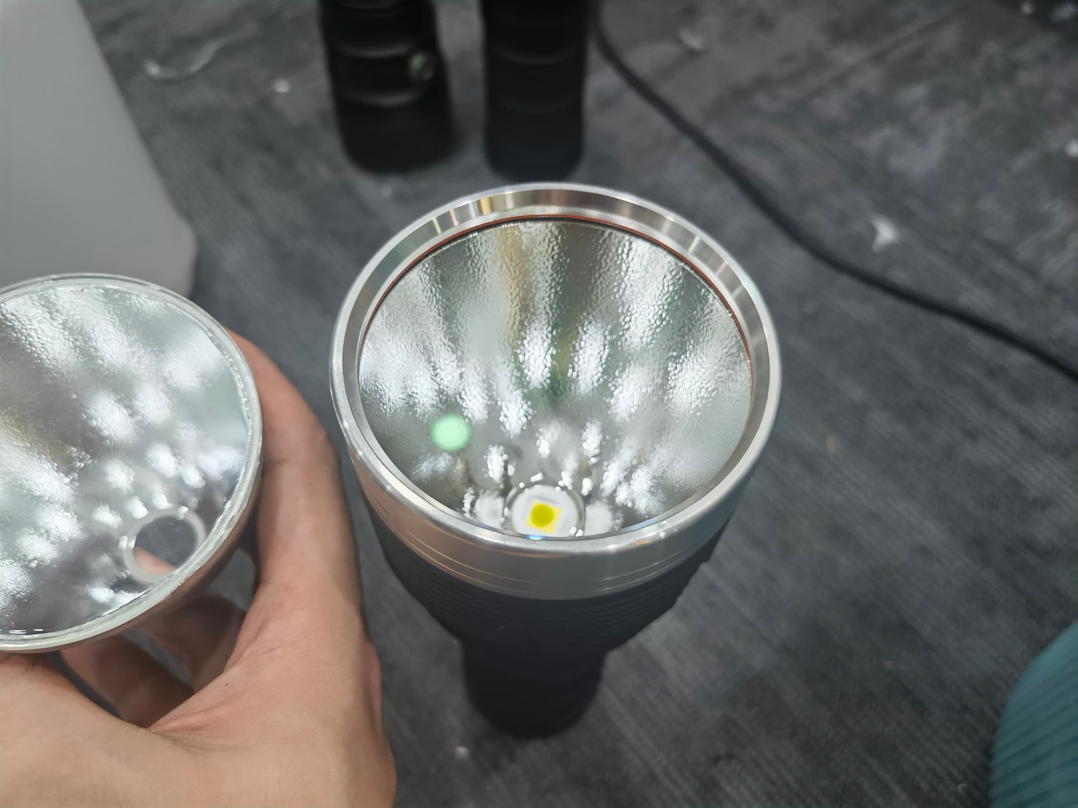
Here is the exterior look when the MCPCB installed into the housing. Larger diameter not only enhancing the thermal performance, but also give my more space for something like NTC connector and auxiliary channel inputs.
Performance
We ordered two type of these custom LEDs which called FI1148D and FI1048D. The FI1048D is the 6V version which use 10x11mm proprietary package.

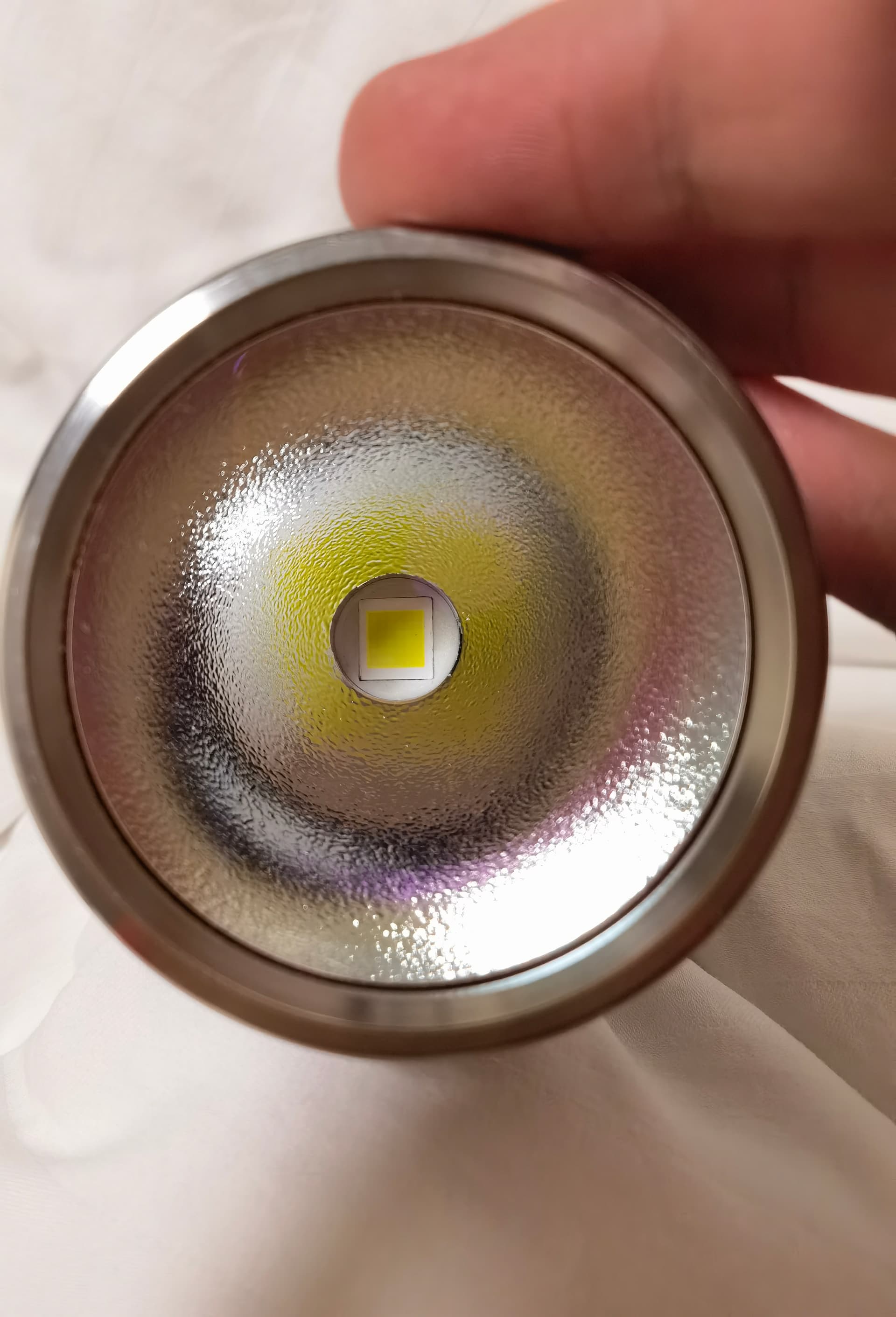
And here is the LES of this LED when driving with my multimeter:
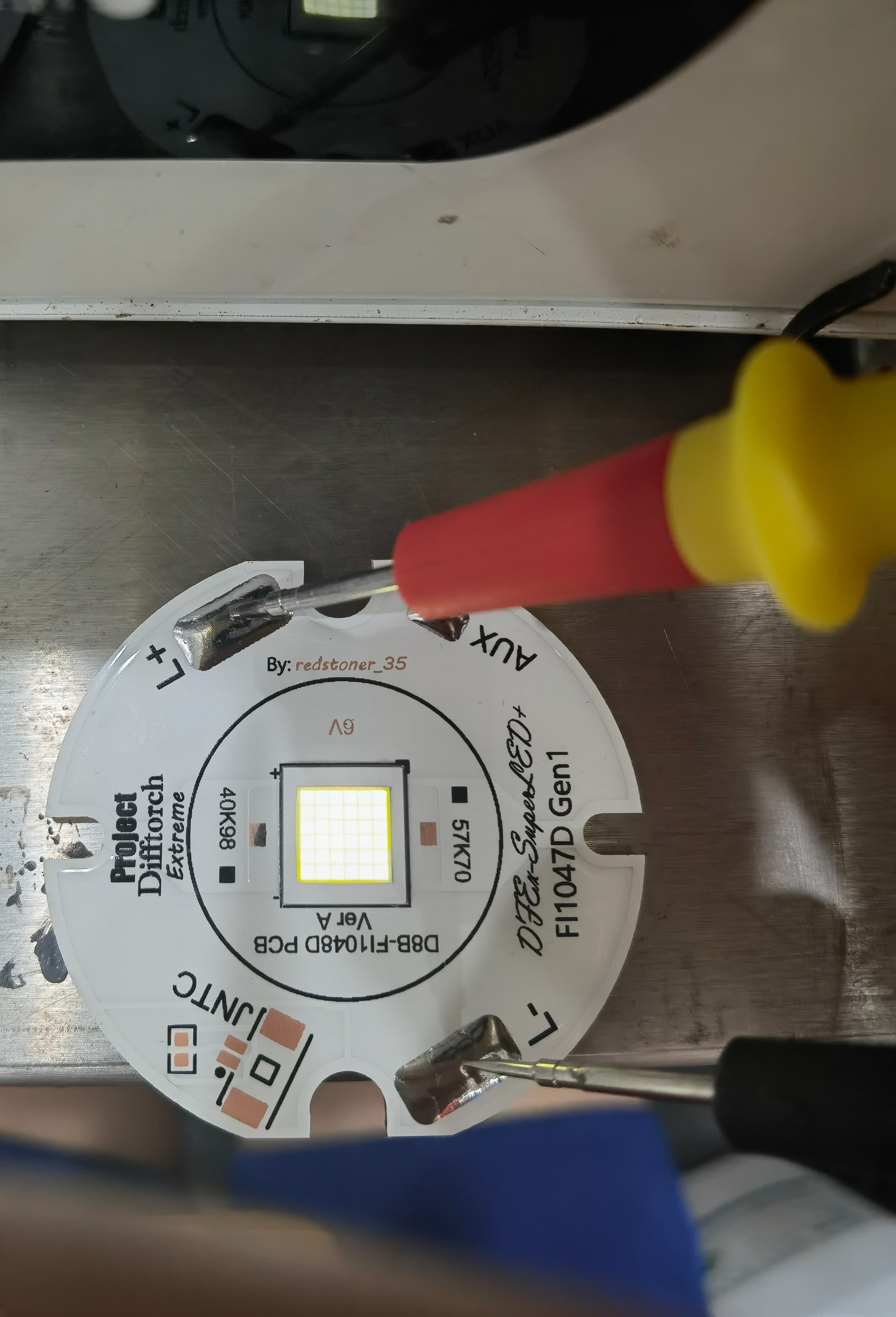
Due to the excellent process capability of the packaging and testing factory, the gap between the cores of these LEDs is set to a very small 80 microns, which ensures the light intensity of the LEDs and avoids the black circle at the center of the light spot.
Here is the typical performance of the FI1048D:
- LES : 48mm2
- Voltage : 6V 2S18P
- CCT : 5500K
- CRI : 68
- Maximum driving current: 45A
- Sweet spot for turbo: 35A
- DUV: 0.0022
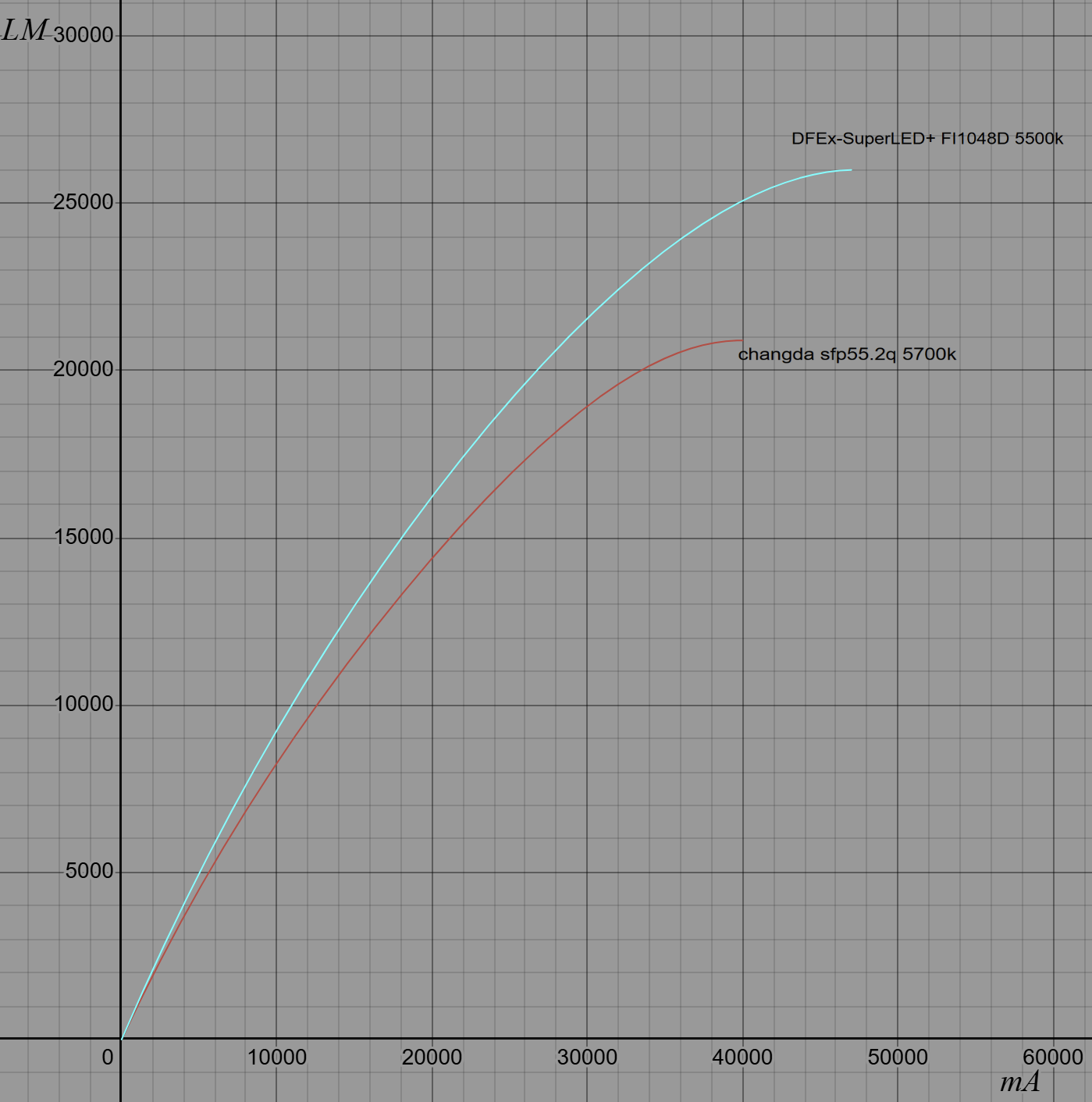
Here is the flux(LM) vs Drive current(mA) graph using a EverFine integrating sphere.Which is absolutely crazy compared to ChangDa SFP55 and Crushing the XFL10K completely. You can get over 21000lm at 30Amps with 6.44V(193.2W) which SFP55 need 45Amps and running at 7.17V With 322.65W of power!
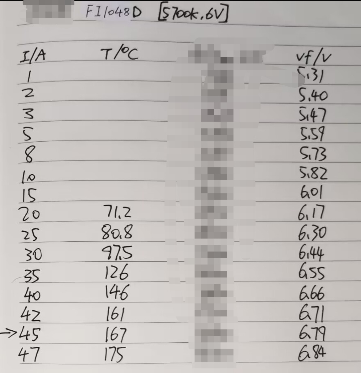
Here is the Vf and Tj data of the FI1048D. which is extremely low compared to XFL10K and SFP55 with only 6.8V at saturation point and 6.4V or less for normal operation.
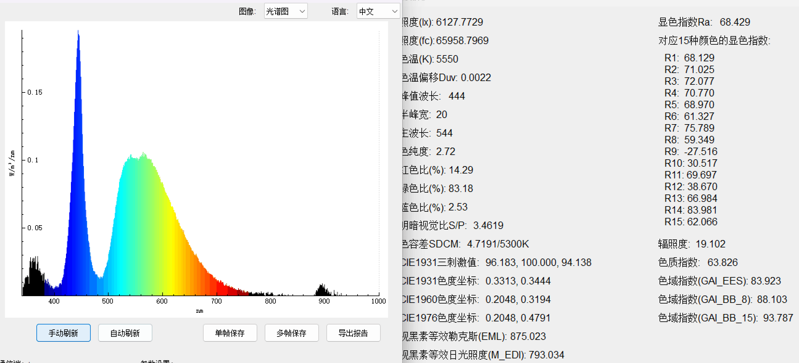
The picture shown above is the measured spectrum of this LED.
beam profile at flashlight
Due to the minimum gap between the dies and a rather small LES(6.95*6.95=48.3025mm2)The beam profile is a combination between thrower and flooder.
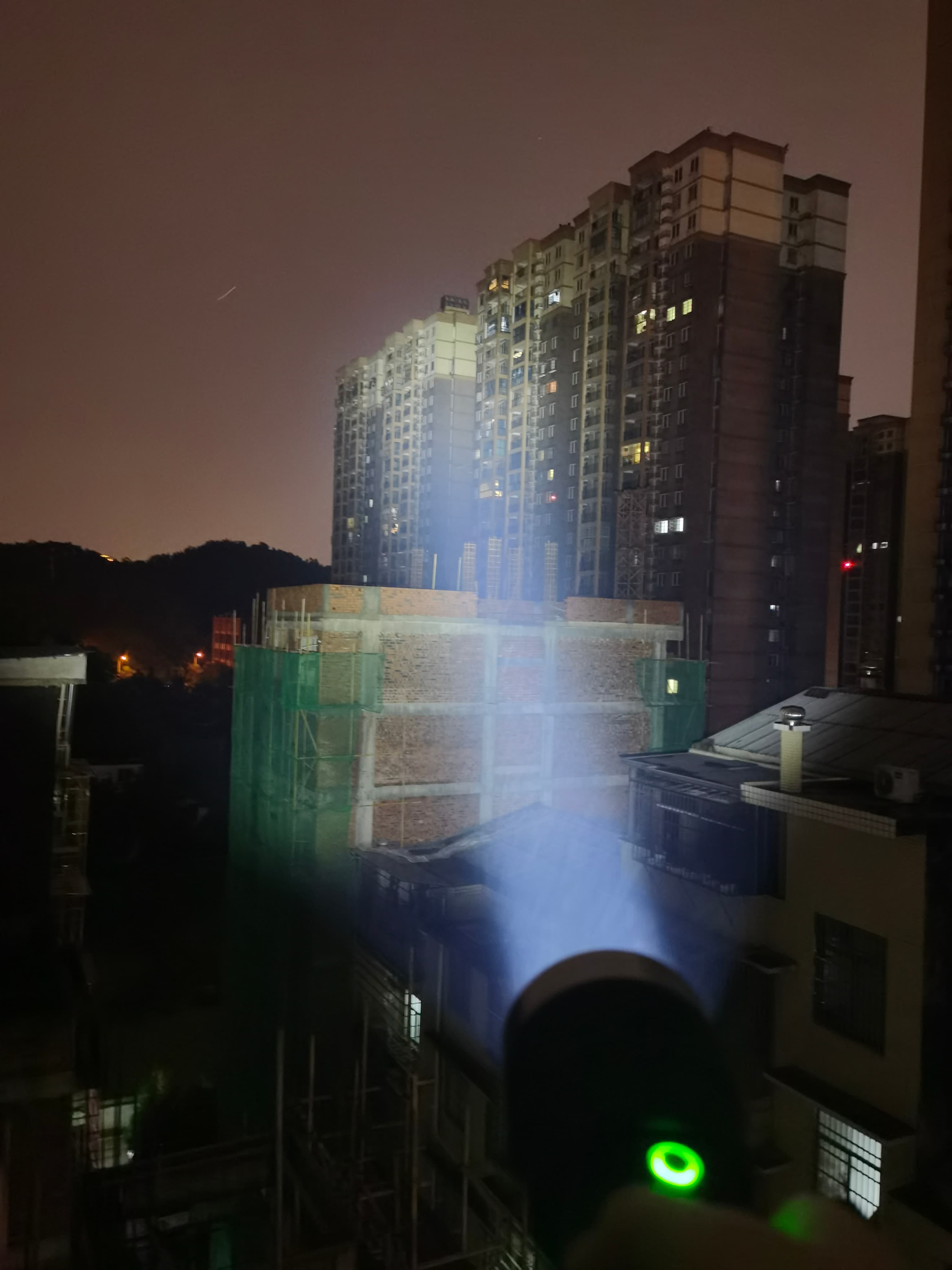
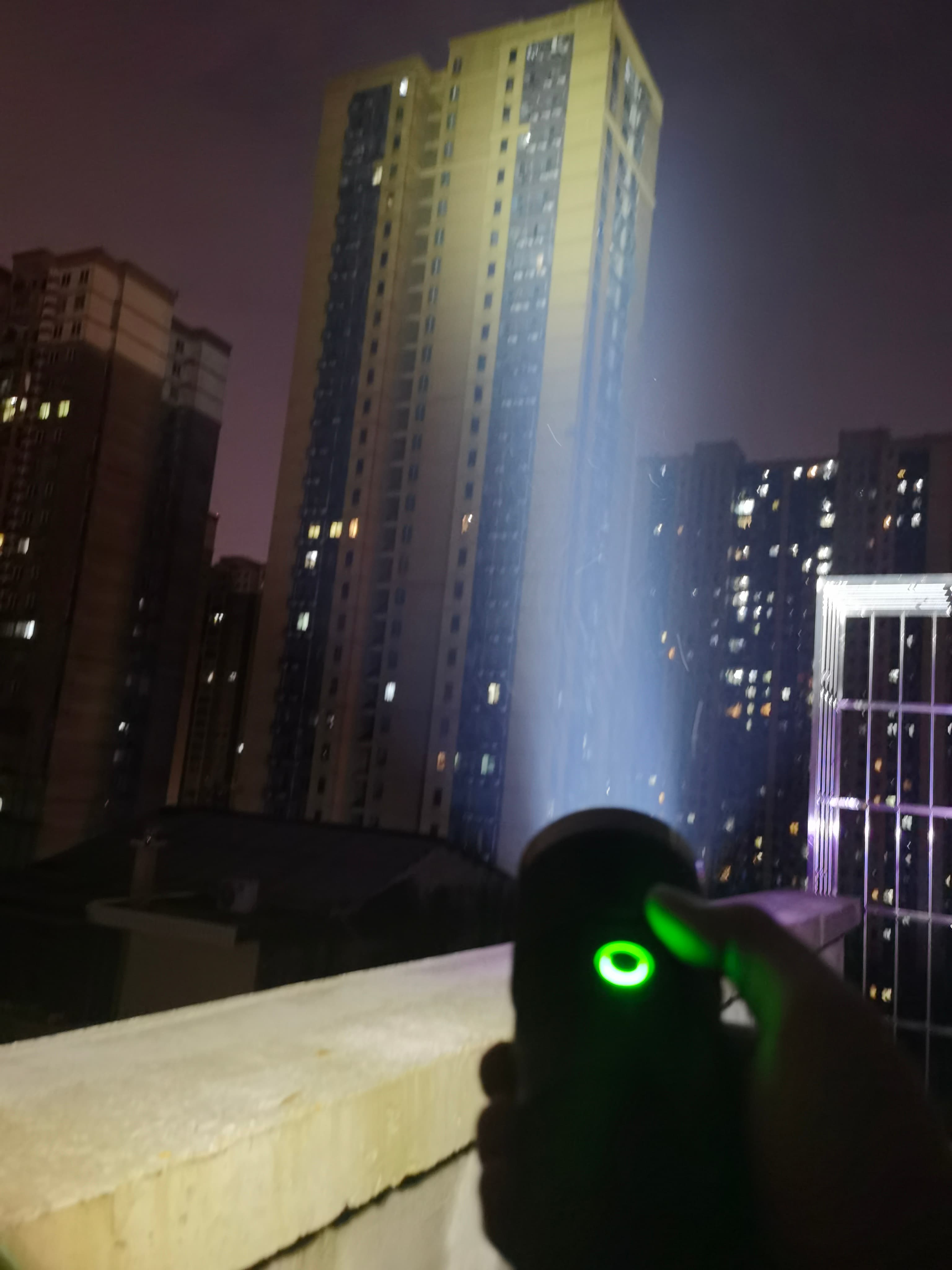
The picture shown above is the CRD flashlight I Built using DDH-D8B housing with a 80mm non-smooth reflector like this:
This CRD flashlight uses the Xtern-Ripper V3 BUCK driver by me and runs at 34Amps when Turbo.

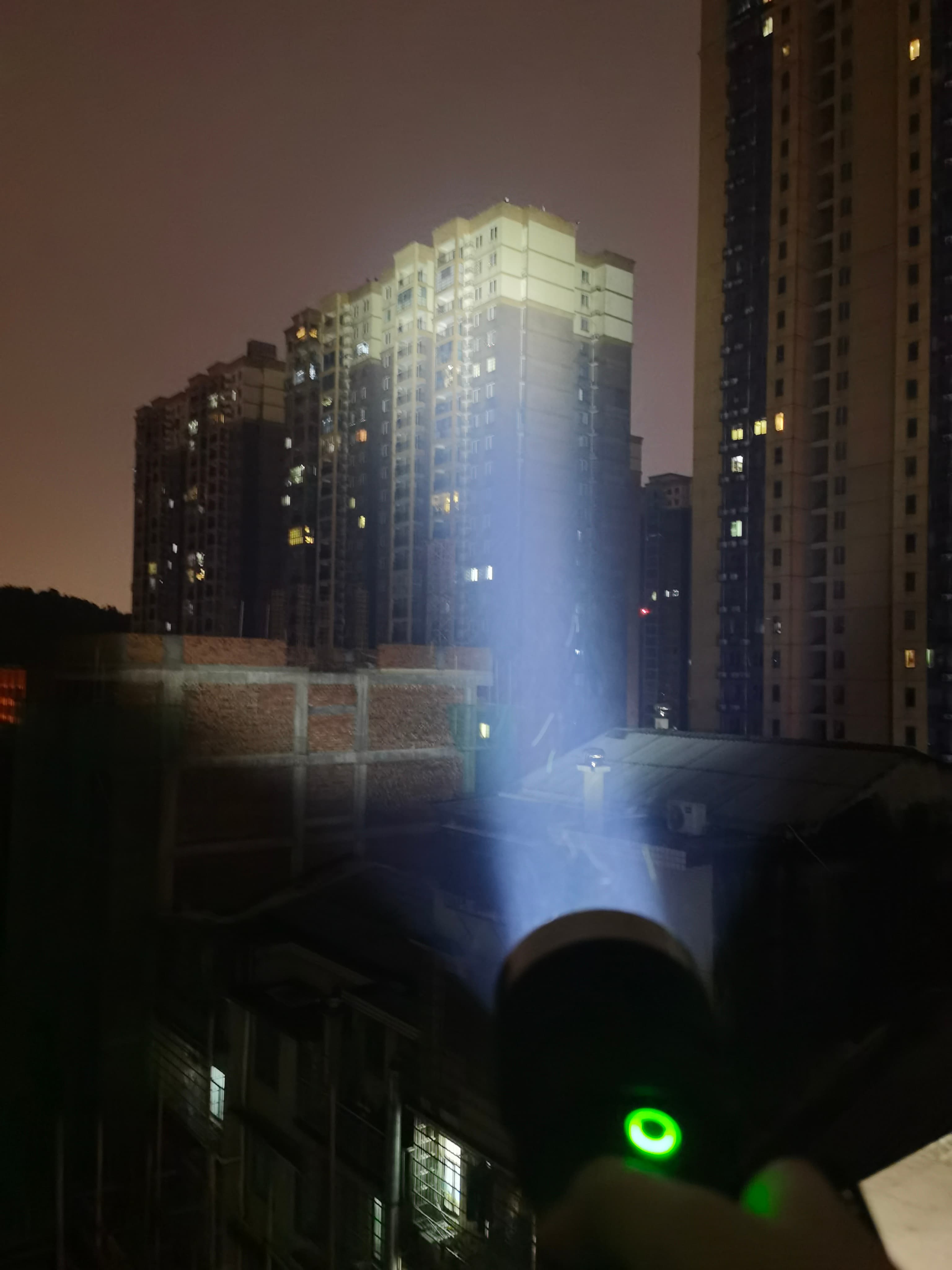
for smaller reflector. the beam profile also looks good with a little bit of center spot. the picture shown above is another CRD flashlight I built with Xtern-Ripper V3 driver(30Amp at turbo) and DDH-D6C housing with 50mm reflector like this: