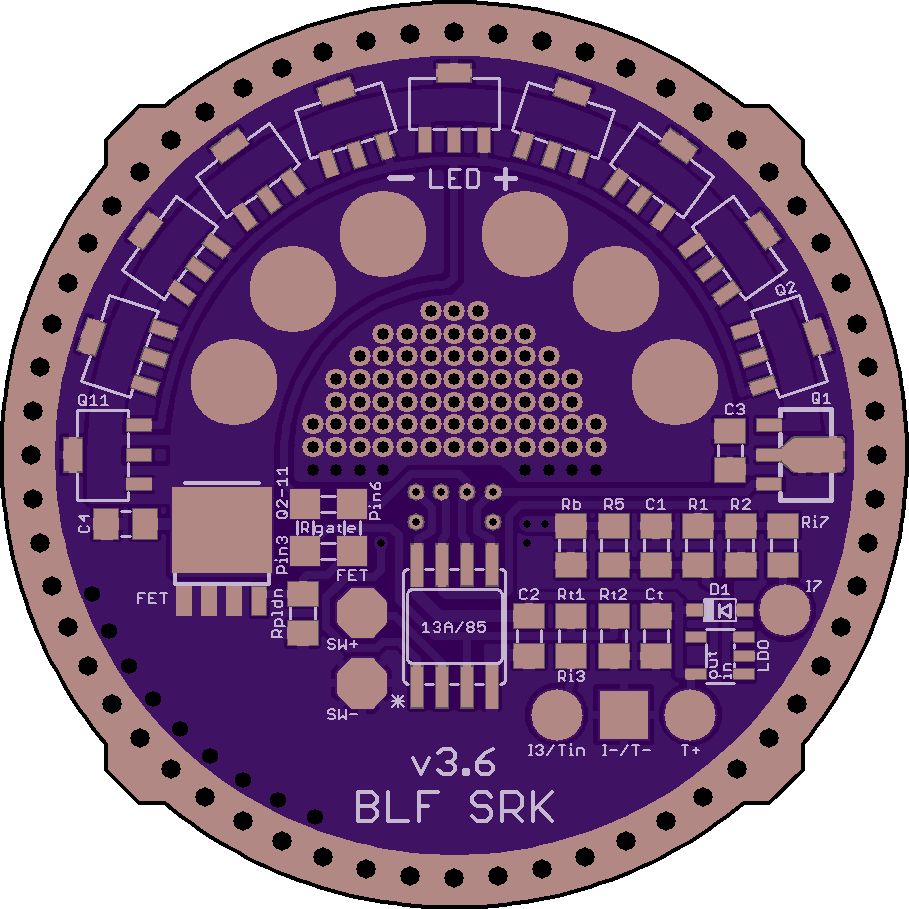
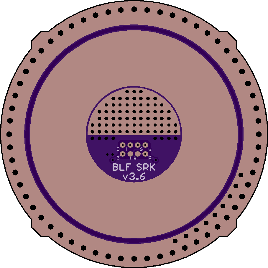
BLF SRK FET v3.6
.
Same circuit, but some major overhaul.
Added Vias for a Programming Key to allow for programming while the driver stays in the light.
Performance optimizations: Even more LED+ vias, more GND vias around the FET, wide path from GND to Source
LED+ vias still unmasked to allow filling with solder and all vias are inside the battery contact circle
LED pads reduced to 2x3, but each pad increased in diameter
Unified the other pads: octagonal for both switch pads, round for I3/I7/Tin/T+, square for I-/T-
Honestly, can’t wait to get these into my SRKs ![]()
.
https://www.oshpark.com/shared_projects/LZhFeMG8
.
.
.
Schematic:

.
Pin5 is hardwired to the single 7135 (Q1) for the low modes.
Pin6 and Pin3 can, using the fancy 4-pad-connector (aka QuadPad), alternatively be connected to Q2-11 or the FET.
For the Attiny13A: use Pin6 for the channel you want to PWM, be it the FET or Q2-11. Use Pin3 for the channel you want to just switch on/off.
Mind that the position of the pads within the QuadPad has changed due to the optimization of the driver.
.
Component list:
- 13A/85: MCU ATtiny13A or 25/45/85; 8S1 (SSU) or 8S2 (20SU)
- FET: n-channel MOSFET at Pin3 or Pin6; LFPAK56
- (Rgate): series gate resistor; use the QuadPad (FET-to-pin3 or FET-to-pin6); 0805
- Rpldn: pulldown resistor (gate to GND); 0805
- Q1: single AMC7135 at pin5; SOT-89
- Q2-11: up to 10 AMC7135 at pin3 or pin6; SOT-89
- R5: series resistor between VCC and MCU pin1; 0805
- D1: schottky diode for 1S (4.2V); SOD-323
- LDO: low dropout regulator for 2S (8.4V) [LDO needs C1 and C2]; SOT-23-5 (Vout is pin5)
- C1: input capacitor between VCC/LED+ [behind R5] and GND; 0805
- C2: decoupling capacitor for MCU; 0805
- C3: additional capacitor between VCC/LED+ and GND; 0805
- C4: capacitor between drain/LED- and GND; 0805
- R1: voltage divider to VCC [before D1 / behind R5]; 0805
- R2: voltage divider to GND; 0805
- Rb: bleeder resistor from VCC to GND; 0805
- SW+: pad for momentary switch to pin2
- SW-: pad for momentary switch to GND
- Tin/Rt1/Rt2/T+/T-/Ct: external temperature sensor
- I3/Ri3/I-: indicator LED at Pin3
- I7/Ri7/I-: indicator LED at Pin7
Notes:
- Rb is parallel to C3 and can be used to add capacitance
- Ct is parallel to C2 and can be used to add capacitance or for a zener diode
- Q1 can be used as Nanjg star 2
- Rt2 can be used as Nanjg star 3
- SW+/SW- can be used for an OTC or as Nanjg star 4
- a momentary switch at Pin3 can be soldered to the QuadPad

