You guys have way too many variables to get any useful information.
A constant current buck regulated power supply is necessary for a proper comparison.
Of course you are correct but I can’t really help the variables because I was not testing a led but making a flashlight. ![]()
We will see how this led works out for other hosts and other people. I have not done my last mod with it for sure. ![]()
Hmm… That will not be 100% reliable method. Why?
You can still mess something up. So I would say your test is ok but there will variables too…
Proper test should include 3 emitters with 3 different re flow methods:
- solder paste(thin or thick appliance),
- lead less solder,
- stencil thin solder paste appliance,
And then there are more like reflowing time and temperature (shorter re flow time means better in my diy book cause emitter can loose properties if you are cooking it to long).
And then when you mentioned buck regulated power supply. Is there budget or pro versions of this and possible differences between them which could influence on final test results?
Freaking variables ![]()
djozz, are you going to do an output test of the 2mm^2 white flat? I bought 4 from mouser and can do an estimated output vs current measurement, though luminarium’s numbers give a rough idea of where the peak is. I will also put it in an EE X6 head and measure the throw while powered by a constant current supply.
For me the real advantage is the very low Vf. I plan to put 4 of these in my C8 quad. A single cell will drive them pretty nicely I think.
Exactly, making a flashlight is completely different from trying to make accurate and repeatable scientific tests.
Totally possible that in your scenario some other LED performs better in that case.
D1S or Jaxman Z1 for this led ?
all look good;
thanks
Thanks for offering doing the test but I wanted to find out myself too now.
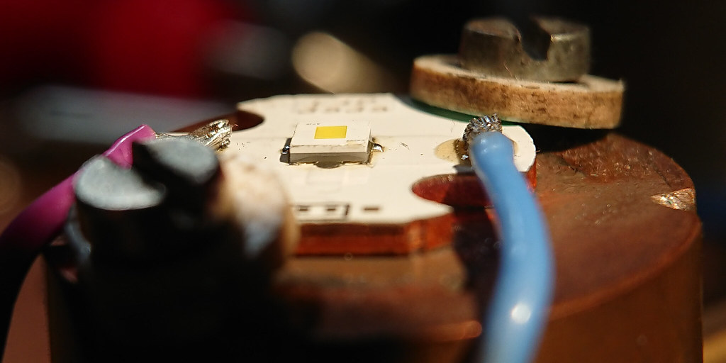
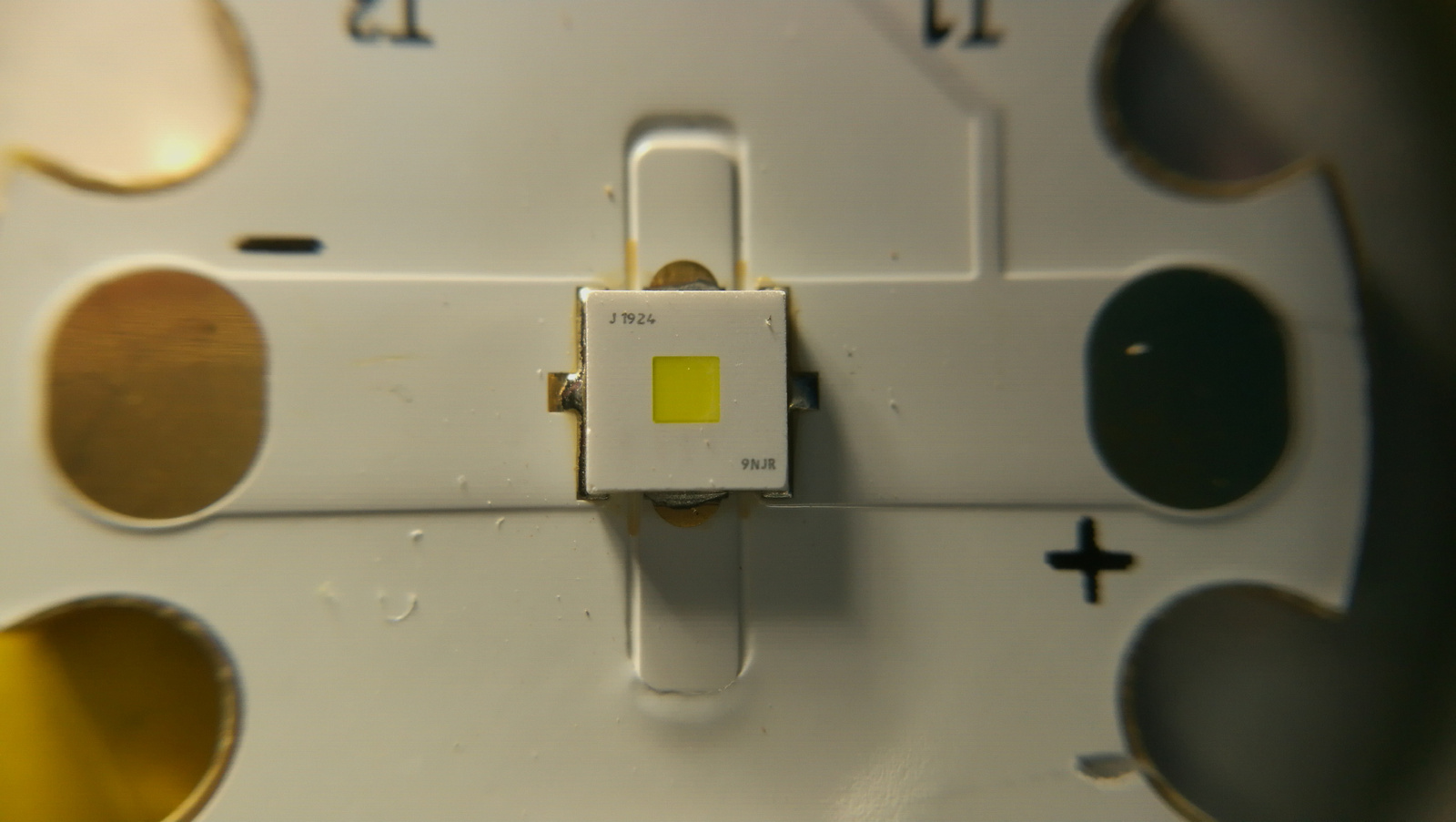
Reflowed a new led on a 16mm L4P DTP board, using enough but sparse solder paste, clamped it well and flat onto the test mount with bit of AS5 in between, and this is what I got:
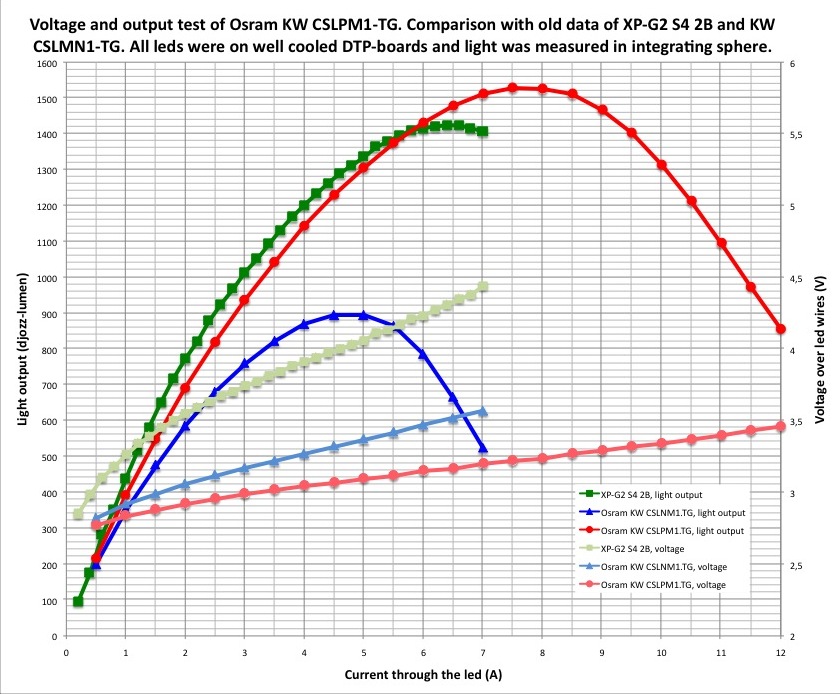
So in my emitter test set-up I find the led peaking lower at 7.5A, and not at 10A as l.i. found. It may be my reflow, it may be the amount or type of my solder paste (same chinese 63/37 solder paste that many use), I don’t know.
Regardless, even in my test this led puts more light out than the XP-G2 S4 2B (the led from the test is not even dedomed, substract 10% output for after dedome), with a maximum output of over 1500 djozzlumen (probably about 1400 real lumen), which because of the low voltage can actually be reached in a single li-ion flashlight (unlike the XP-G2 S4 2B, that you will not get over 4.5-5A).
I do not know why I did not get better performance in my mini-GT, even though I thought that I had done the mod well, but as said before: so many variables…
(I always treat my emitters very well)
I think Vinh announce his newest mod and pick 3.4v for 1mm2 and 3.3v for 2mm2, your graph match that perfectly.
EDIT looks like Vinh might have got the numbers from led4power because they are totally same.
You said and the graph says KW CSLNM1.TG but that has perfect squaare die. But on the led image it is not square. Is something mixed up?
His graph has both the CSLNM1.TG and the CSLPM1.TG.
One is square die and the other is not.
The most recent test he is talking about right now is the CSLPM1.TG which has a rectangular die.
![]()
It is too early morning for me! Need a coffee!
Sorry!
![]()
Thanks for the test!
That’s a somewhat dissapointing result in terms of brightness! The low Vf is great. It might just be that you tested a low performing sample.
The Q8WP that koef3 tested a while ago got up to 9.6A (although his cooling setup might be slightly better).
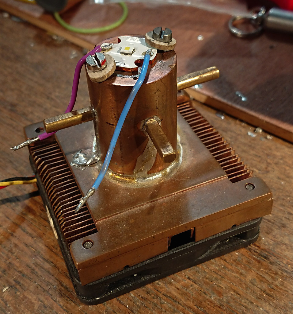
Yes, I get consistent lower thermal performance than other led-testers, if it is the reflow and/or the amount of cooling from my copper mount I do not exactly know. I could order a mounted led from l4p (he uses a different solder) and see if that tests different but I was planning a sort of half test-retirement anyway in which I mainly test for my own builds (and post the test for others to get at least an impression), and the results that I get are certainly relevant for myself.
Djozz after seeing your cooling setup I think that that is your problem.
You have too much copper between the LED and the fins. Copper is a great heatsink and can store a good amount of heat but it’s not as fast in conducting it.
I think the temperature is getting too high as it can’t get rid of it quickly enough.
It might be better if you just took a modern cpu cooler (something like the last generations from and or Intel) and mount the led directly on it.
Q8WP and PM1 basically use same chip, so why you would expect some drastic increase in performance? Q8WP is in bigger package which could explain a little bit higher max. current, but you can also see that lumen output barely rises over 8Amps, which means chip itself is close to its limit at 8+Amps anyway.
Also,Q8WP has some side emitted lumens, PM1 emits light only from front side, which should make it better for cd/mm2 performance, even for same lm output vs Q8WP.
You basically have best 2mm2 throw LED which is brighter than any other 2mm2 LED,has lower Vf than any other LED (per mm2), it's factory dedomed,has nice neutral (non-green) tint and you are disappointed?
I don't if it's just me, but lately BLF = Never good enoughTM
Q8WP had the same peak intensity as HWQP. Same generation, same performance in a nearly 2 times larger die.
NM1 is a significant improvement over HWQP, better intensity, lower Vf. I expected PM1 to be improvement over Q8WP as well. I didn’t expect it to have the same intensity as NM1 because it has the same thermal pad size with double die size, but nevertheless I expected that Q8WP would be beaten. Now it doesn’t seem so, though we lack data to know for sure. Due to symmetric package as well as common footprint it is easier to use, but that’s just that. Well, it is also easier to get. ![]()
I think that PM1 is an awesome LED and I would find many uses for it, but nevertheless I expected more from it.
This could definitely be a reason for lower peaks, I don't know dimensions of that piece of copper rod, but I took 25mm diameter and 35mm length, and result is about 0.2C/W of additional thermal resistance, this could be enough to cause lower peak currents and lower lumens, but not by much for smaller LEDs,depends a lot on LED C/W itself,and total power.
I sometimes directly after a test feel the ledmount with my hand and it was never hotter than luke-warm, even when testing the XHP70.2 led. So if keeping the mount under the ledboard right at 20 degC or 40degC explains a much lower thermal performance then yes, my long mount is to blame for lower performance. In that case most flashlight builds will suffer from the same problem. Btw, among metals copper is about the fastest thermal conductor on the planet/universe.
The copper rod is 30mm diameter and about 60mm long (not at home so I can’t exactly measure). I need it to lower the led inside the sphere while still keeping access to the ledwires.
I could save half the length of the copper bar by using 4 times longer ledwires and guide them through the heatsink to the side of the fan. Longer ledwires would influence the measured voltage at higher currents somewhat, or for each led-test I should solder separate wires on the board for voltage measurements.
But my life does not depend on these tests, nor are my flashlight builds different if they were that bit more accurate. so I just may leave my set-up as it is and hope for Koef3 or maukka to test these leds too and go the extra mile in accuracy.