4/19/14 update
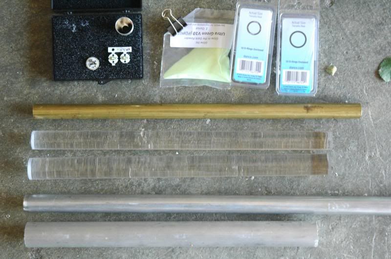
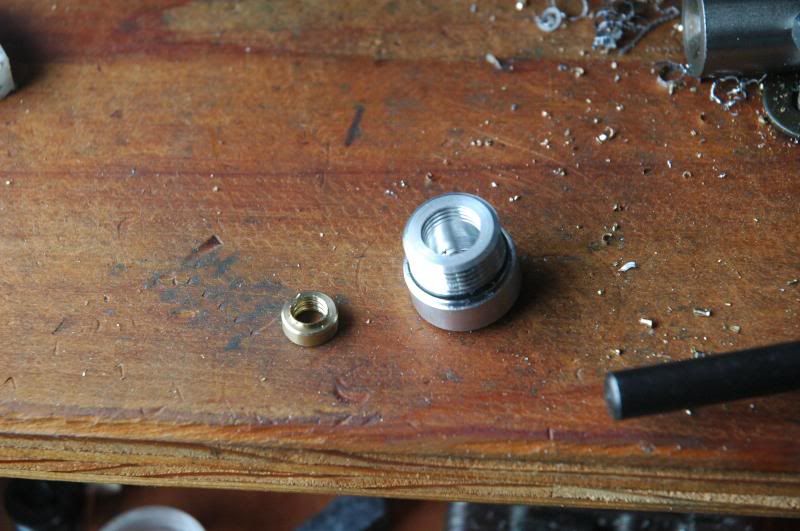
Most of the raw materials needed to make this light
From the upper left to bottom, left to right - wquiles Joule Thief driver, XP-E, 17mm reflector, V10 glow powder, assorted O-rings, 5/8” brass rod, 3/4” clear acrylic rod, 7/8” clear acrylic rod, 3/4” 7075 T6 aluminmum rod, 1” 6061 T6 aluminum rod
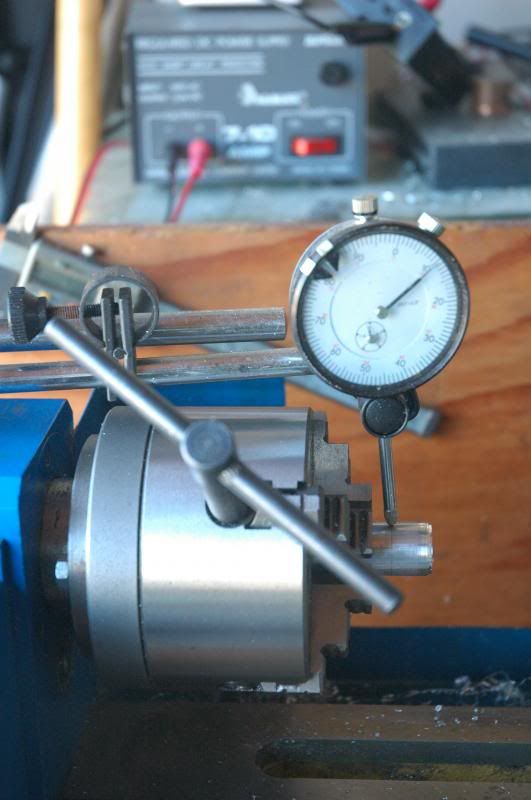
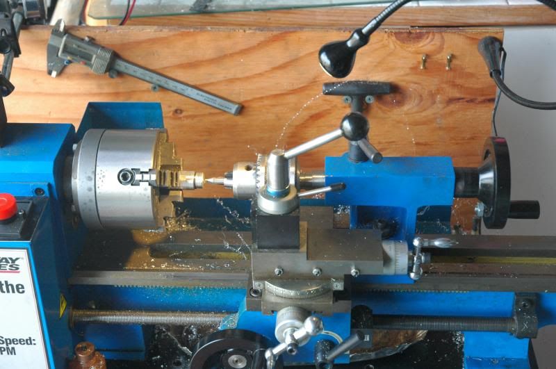
My lathe - Speedway something or other

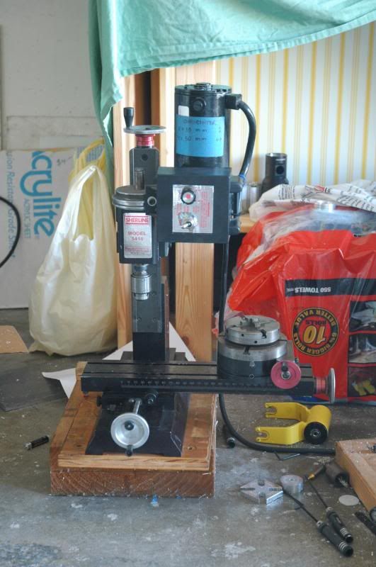
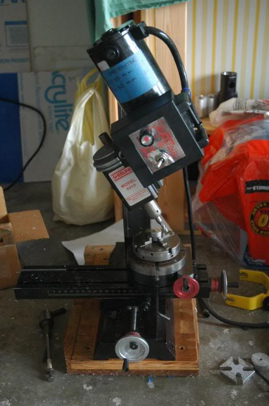
My mill - Sherline 5410
I decided to start with the tailcap since this is easier to make than the head and the body should be done last.
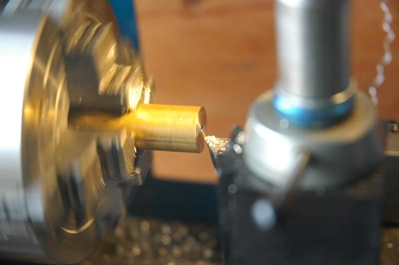
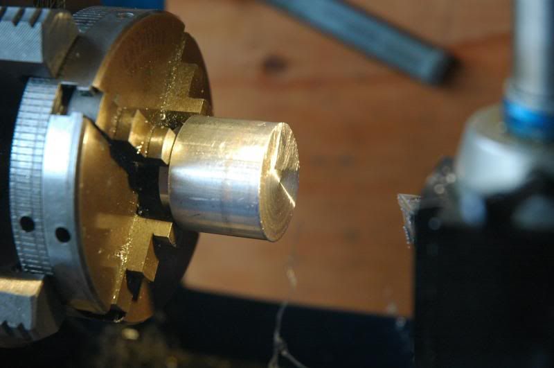
First, chuck the 3/4” 7075 in the lathe
Face the end
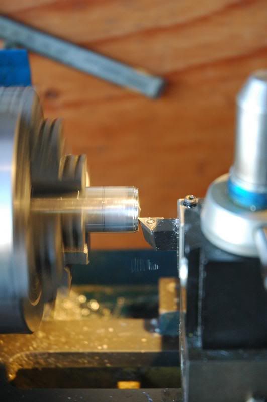
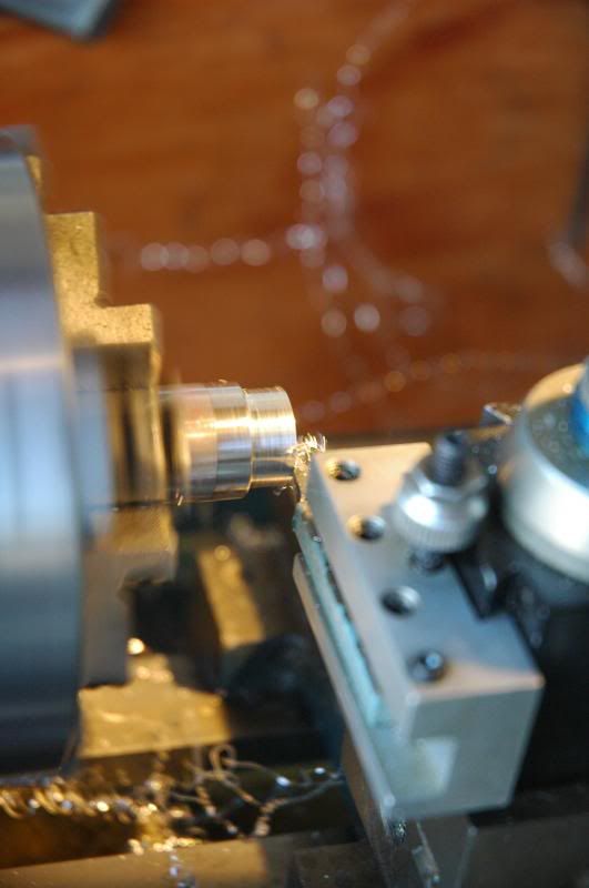
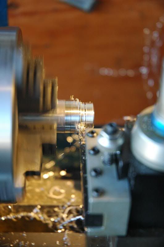
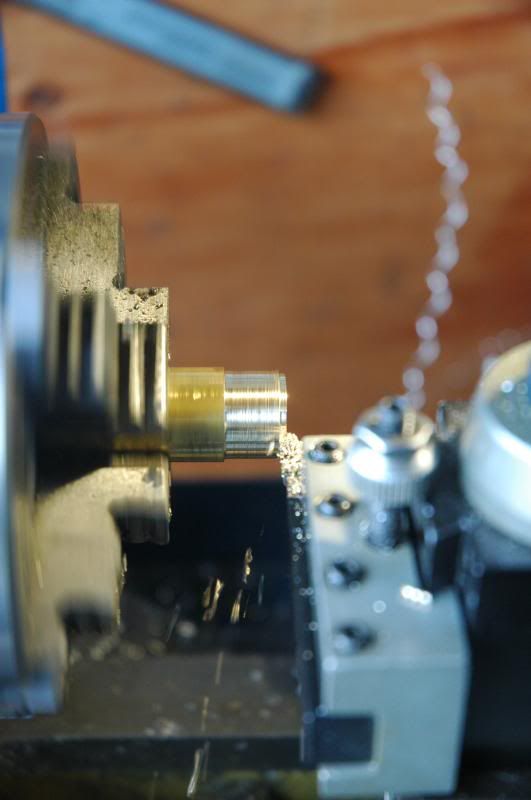
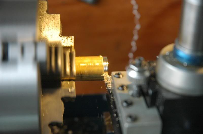
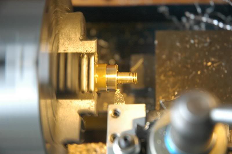
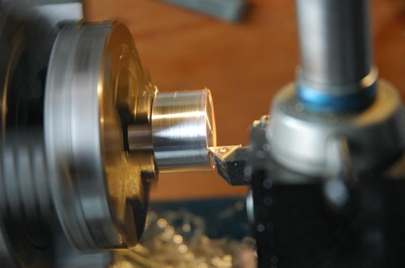
Lightly turn down the outside
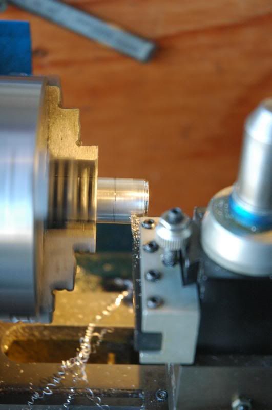
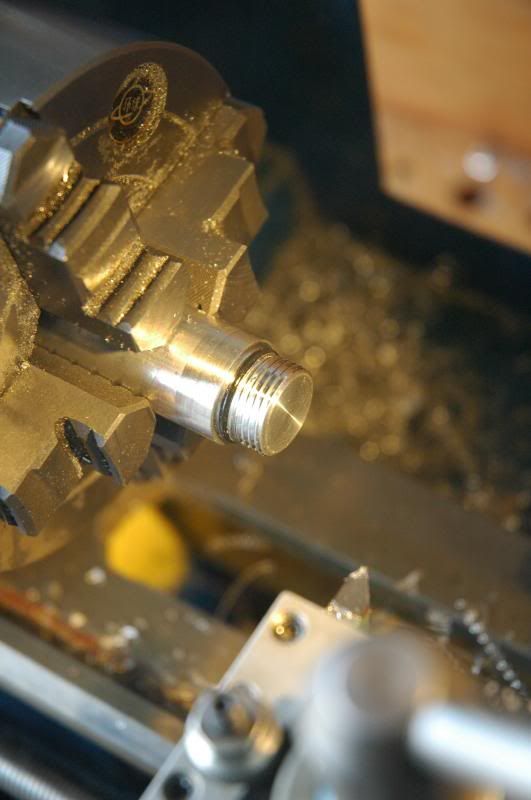
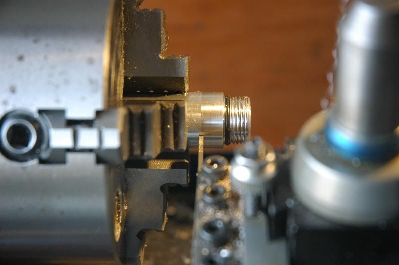
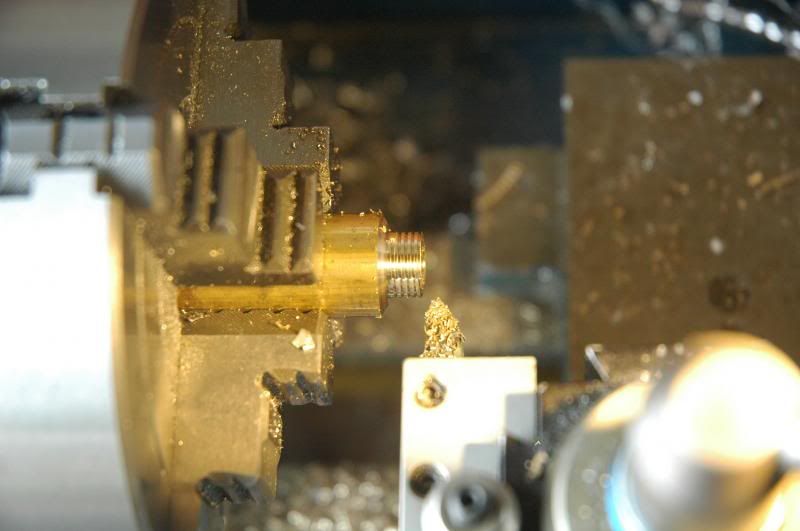
Turn down the threaded portion
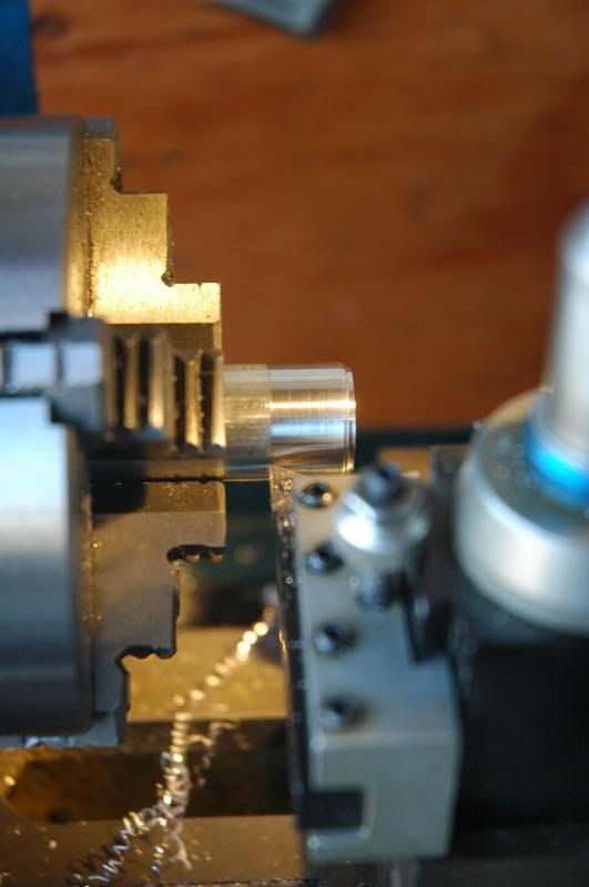
Cut it down to the target diameter of 16mm
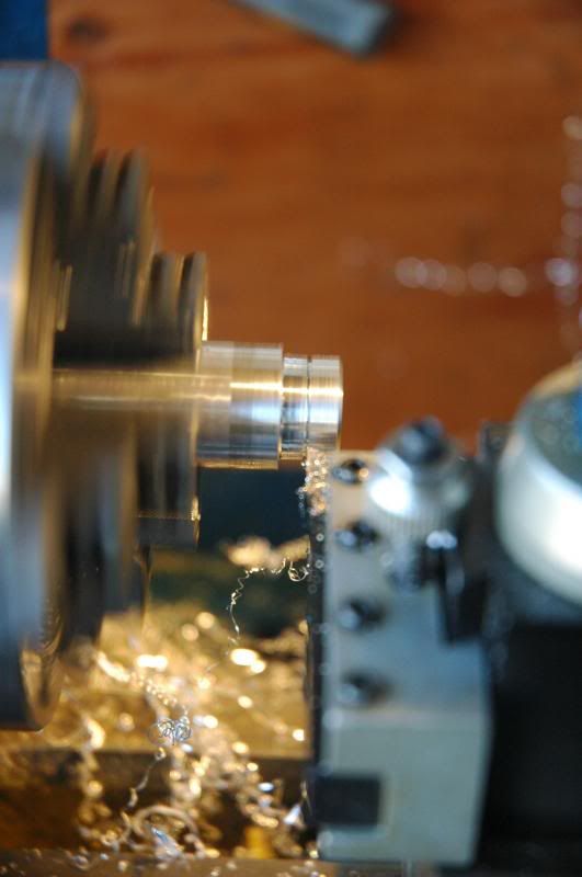
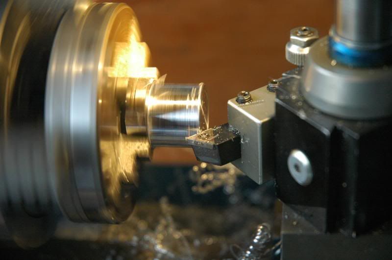
Using the threading cutter, debur the sharp edges
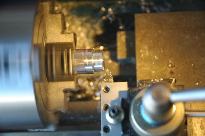
Cut a groove where the threads are going to end
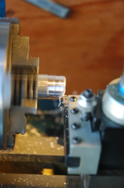
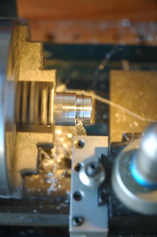
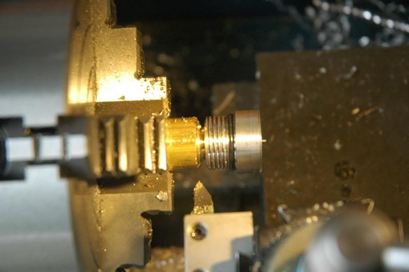
At this point I didn’t like the amount of threads that I was going to end up with so I decided to cut the shoulder back and give it more threads
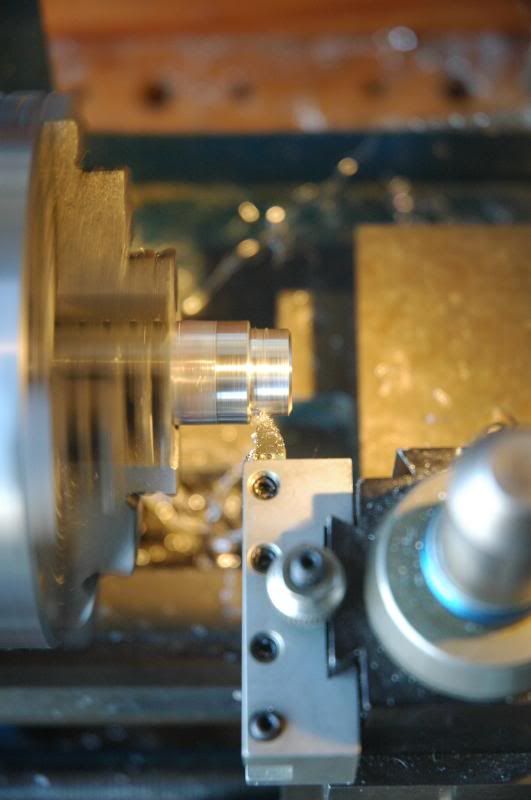
Cut a new groove for where the threads are going to end
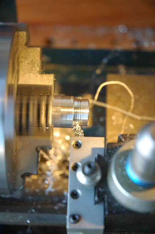
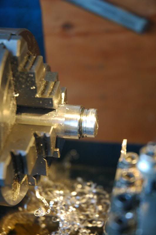
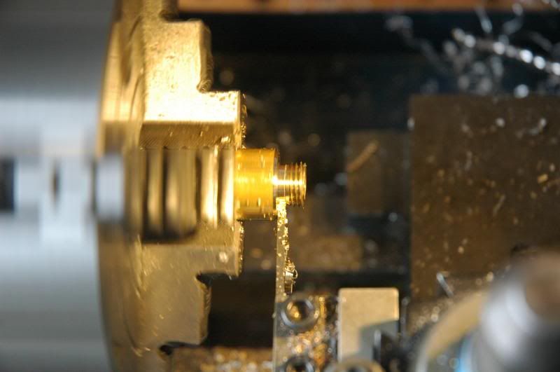
Using the parting tool, cut a groove for the O-ring and install it
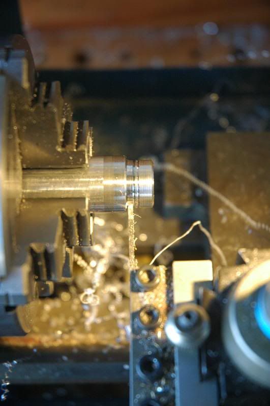
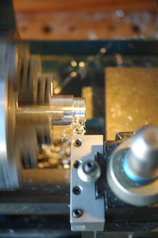
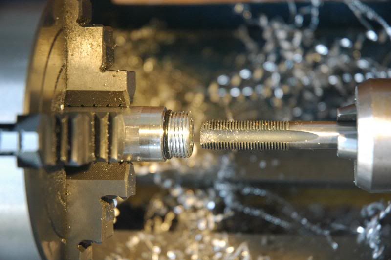
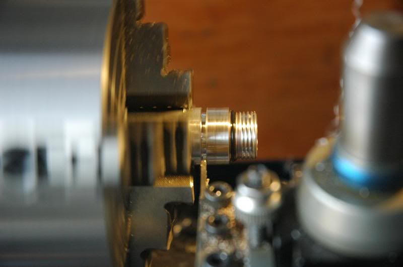
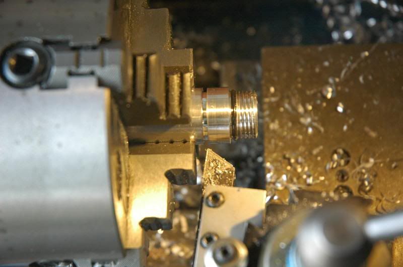
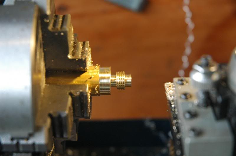
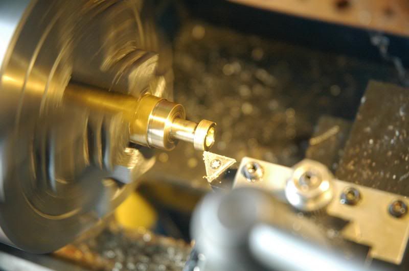
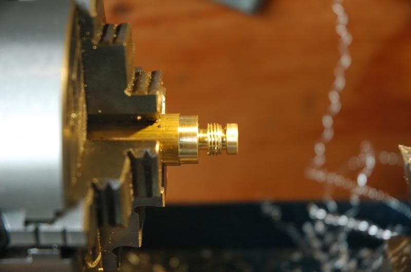
Cut threads
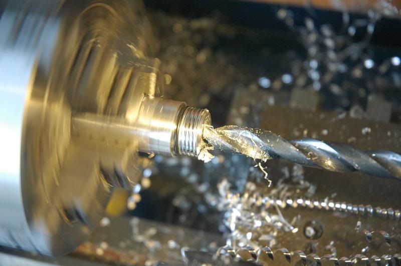
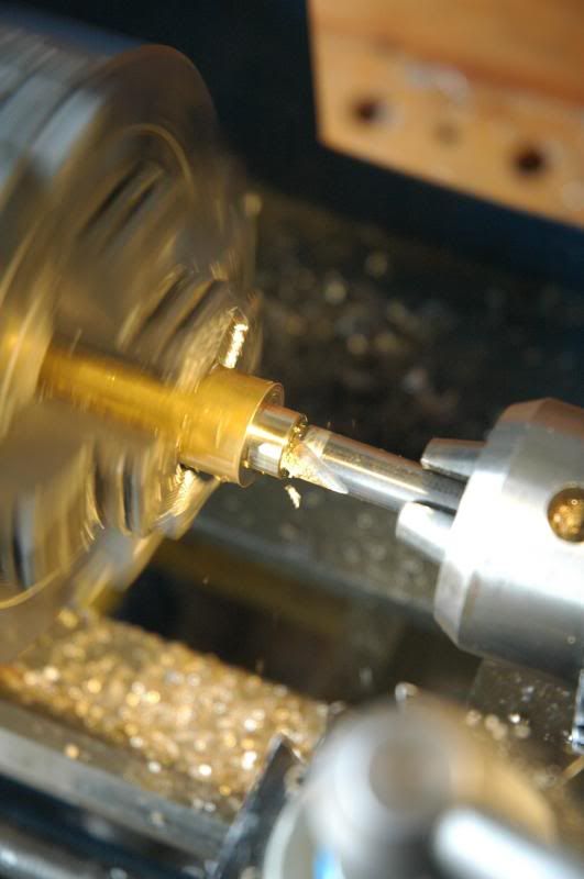
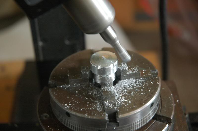
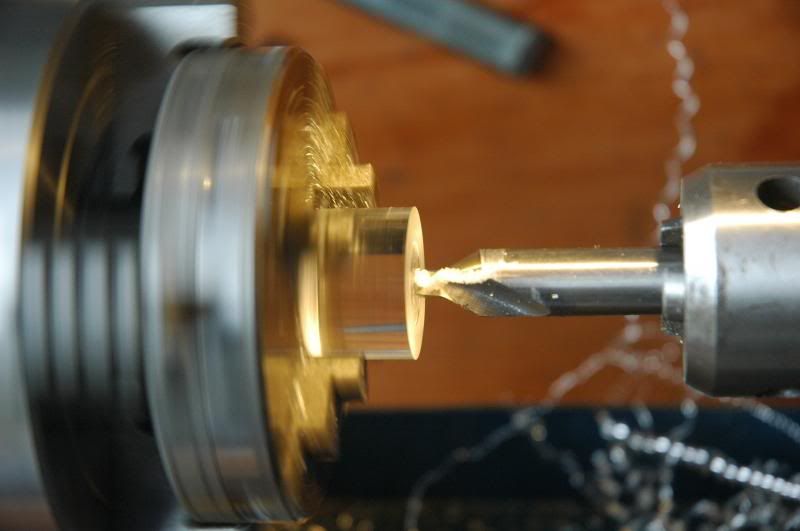
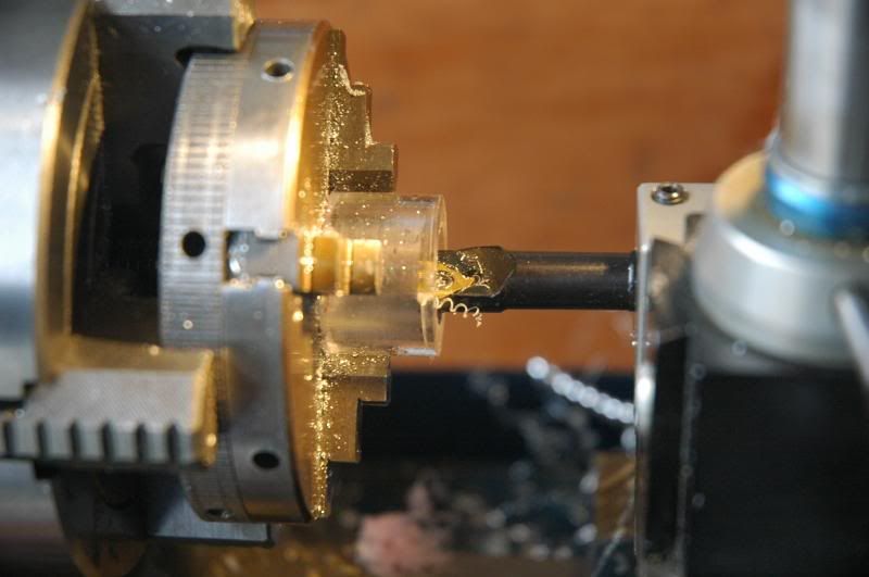
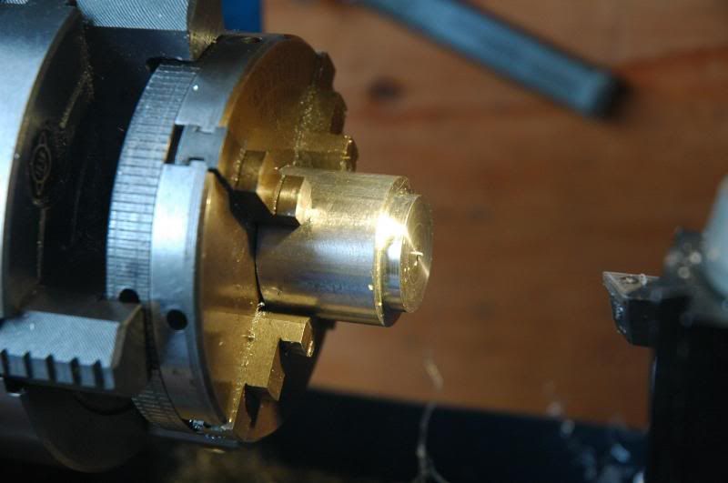
The setup for drilling out the tailcap
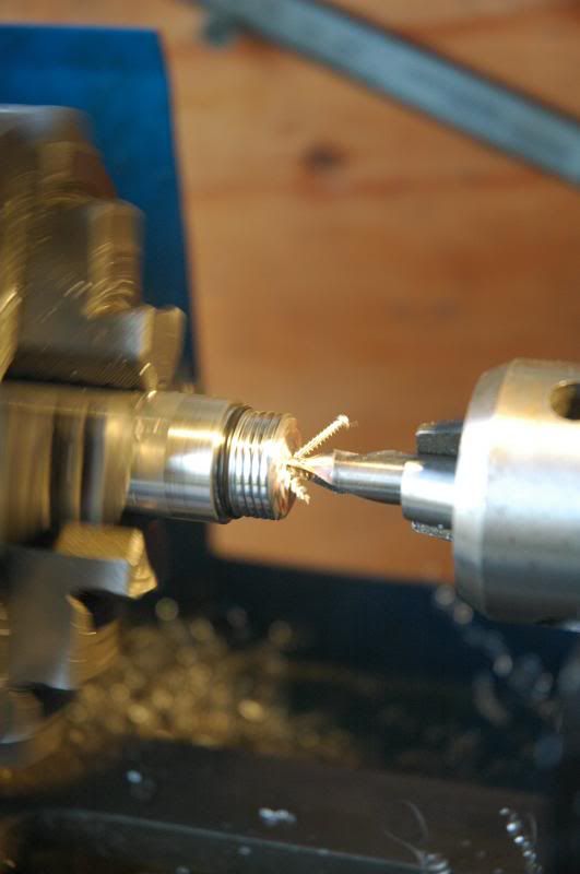
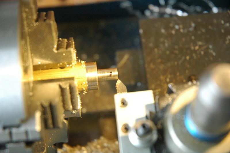
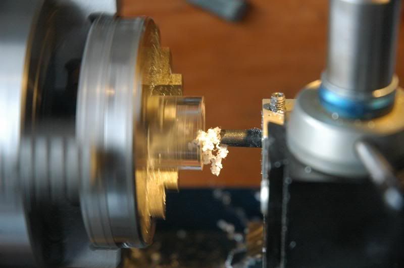
Starting the drilling with a centering drill bit
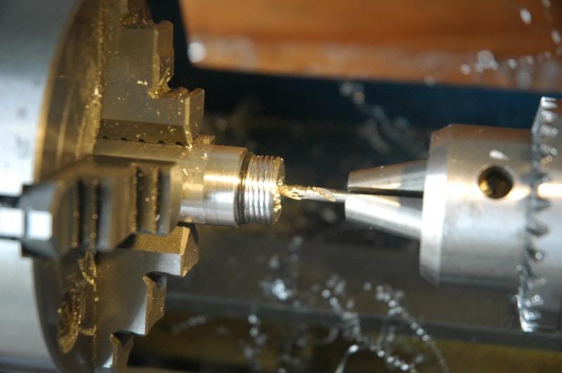
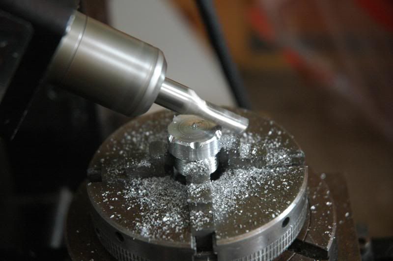
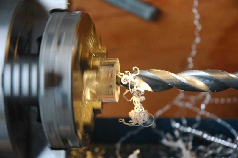
Moving on to a 1/8” drill bit then a 1/4” bit and eventually the 3/8” bit going only 9/16” deep
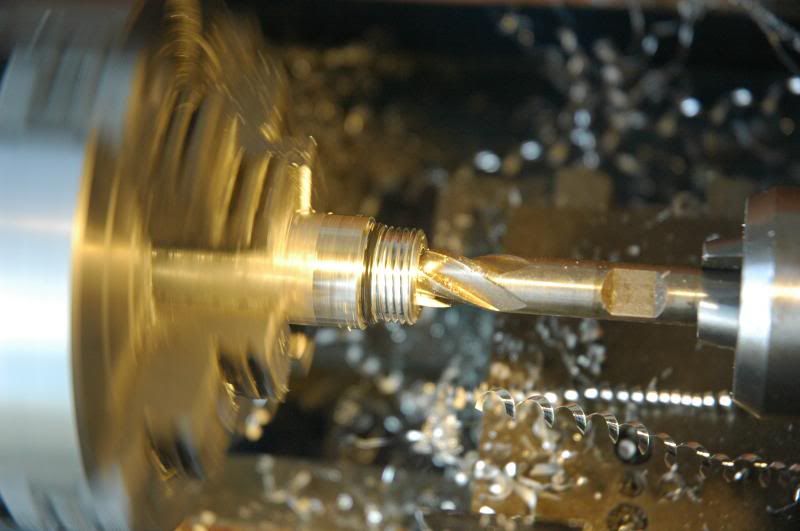
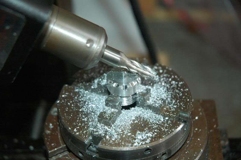
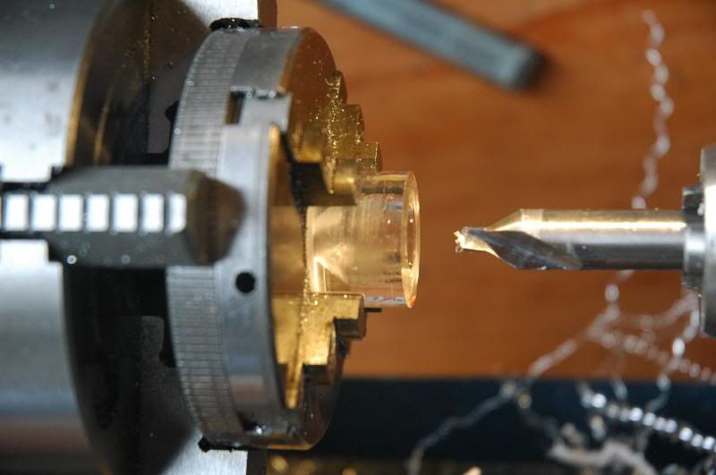
Chucked a 3/8” end mill in the drill chuck and squared off the corners inside the hole since the drill bits leave an angled hole bottom
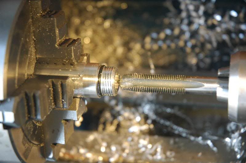
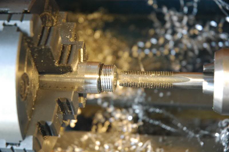
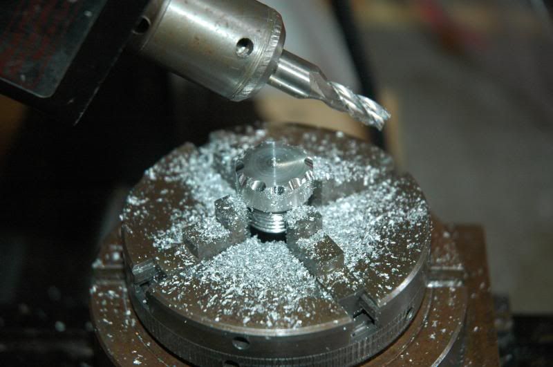
The next three operations use three M10X1 taps, the first being a standard tap, the second being a modified one that is almost bottoming, followed by a bottoming tap. Only about three threads are cut
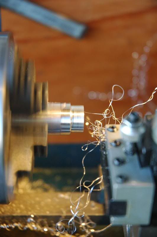
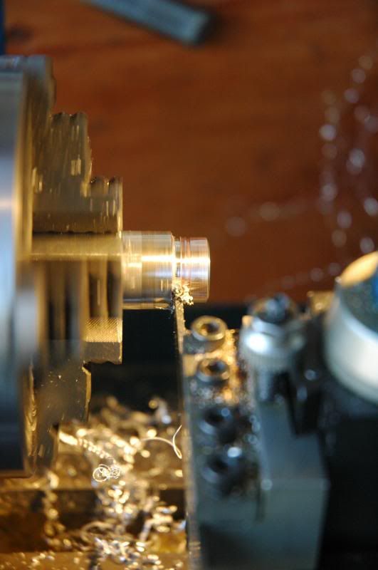
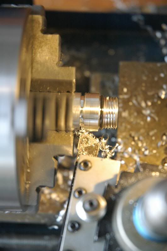
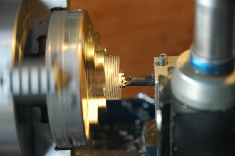
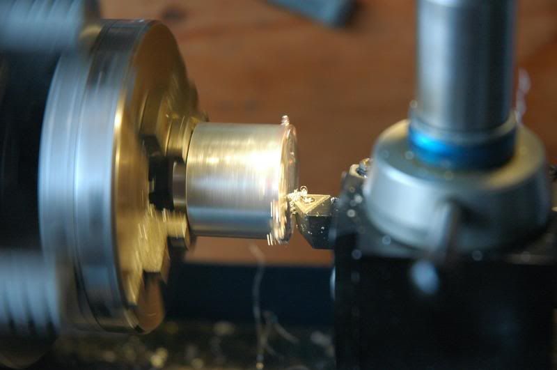
Using the parting tool, start parting, but, stop after a few millimeters
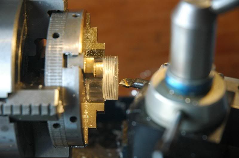
Reinstall the turning cutter and rotate it 15 degrees to put the cutting edge at a 45 degree angle
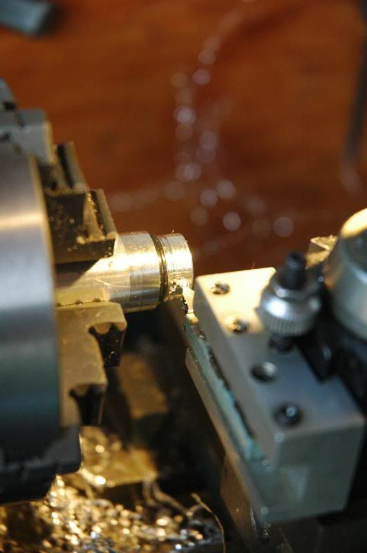
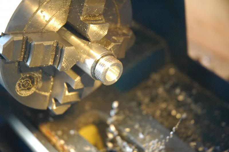
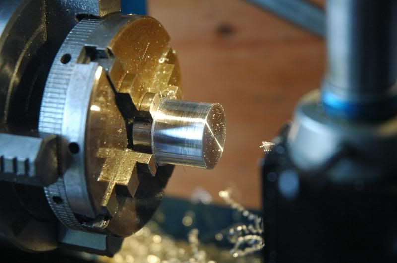
Cut a 45 degree bevel then finish parting the tailcap
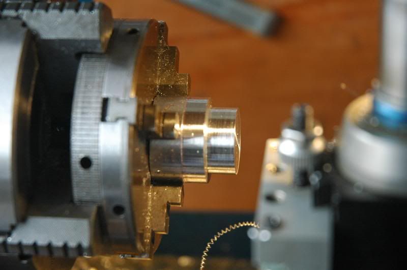
Remove the 3/4” aluminum and chuck the 5/8” brass then center it
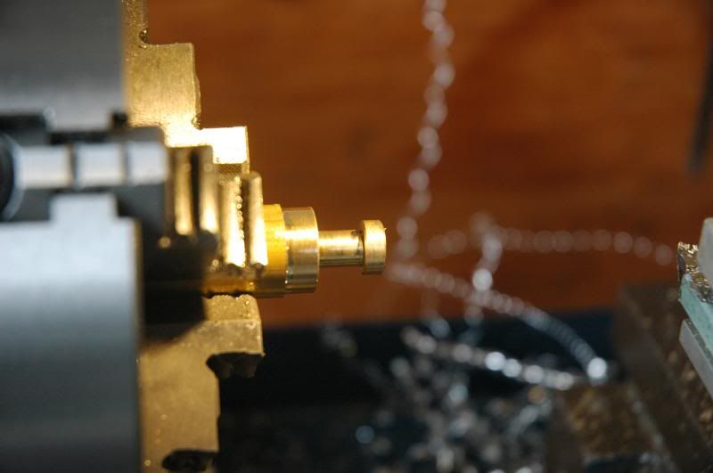
After a quick facing operation turn it down to 10mm then cut half of it to 3/8” diameter, about 9.4mm
The tailcap slides onto the narrower part, but, not the wider part
Cut a groove to differentiate the two parts I’m making. There are two retaining rings being made
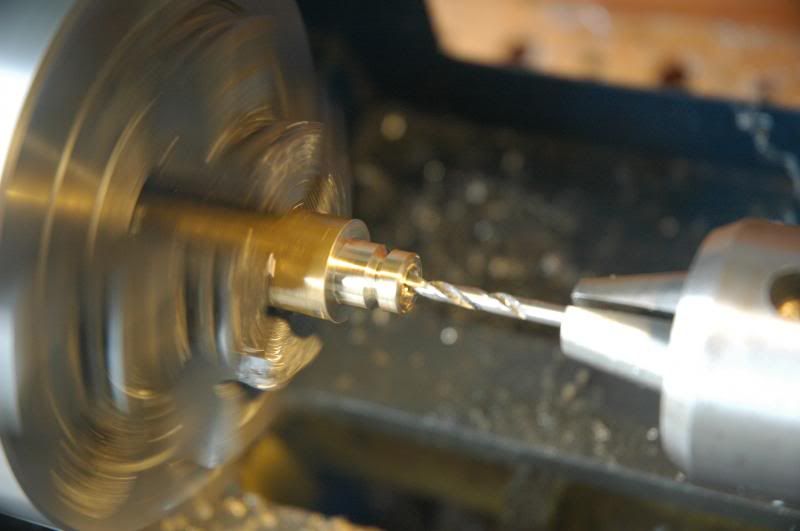
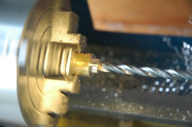
Using the center drill again, start a hole, followed by a 1/8” drill then a 7/32” drill
Using a 1/4”X20TPI tap, tap the hole

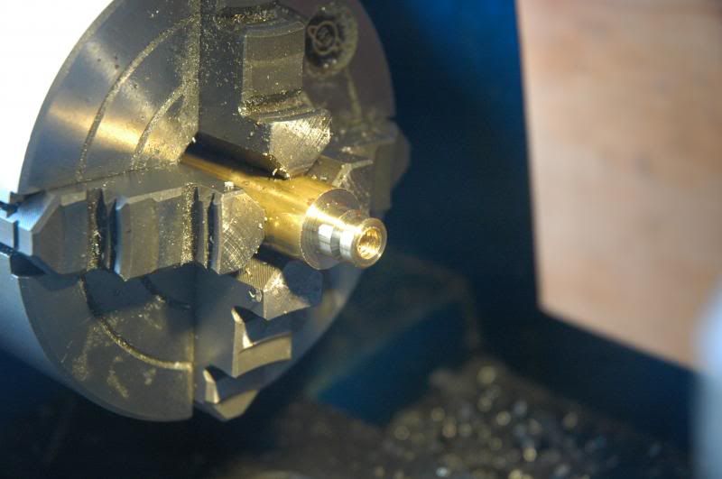
Part off the internally threaded retaining ring
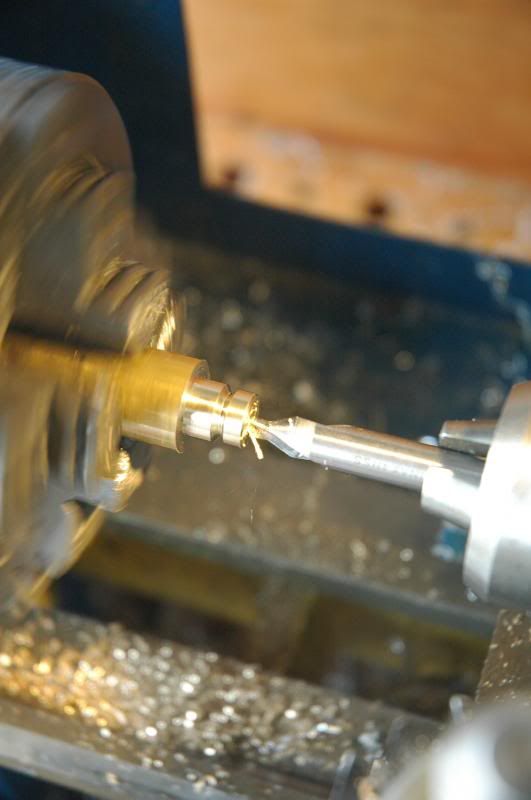
Using the centering drill, clean up the edge so that the drill bit goes in straight
Using the threading cutter, bevel the hard shoulder for clearance before threading
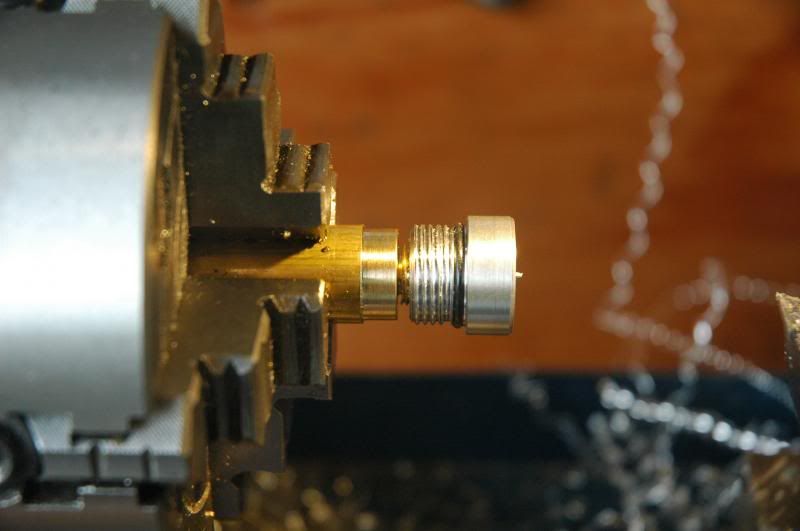
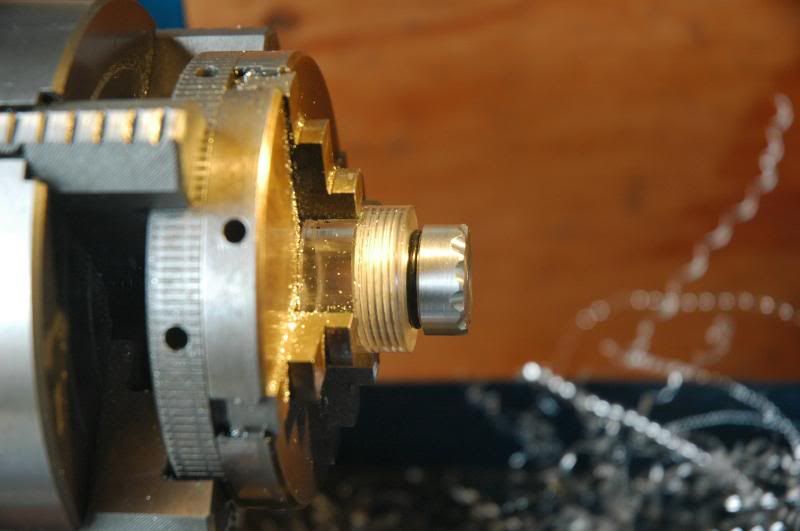
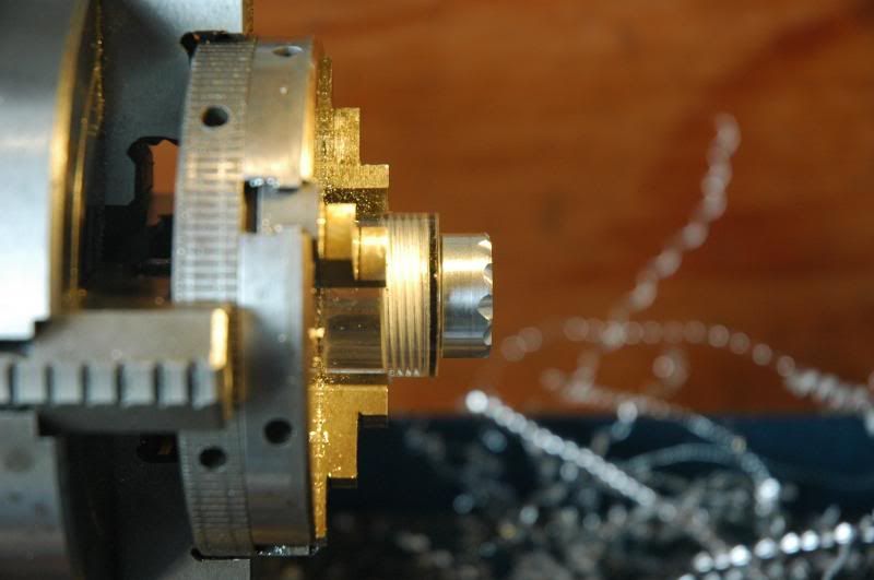
The tailcap threads onto it
Part it off
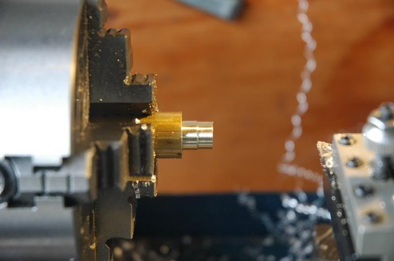
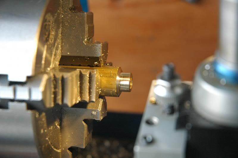
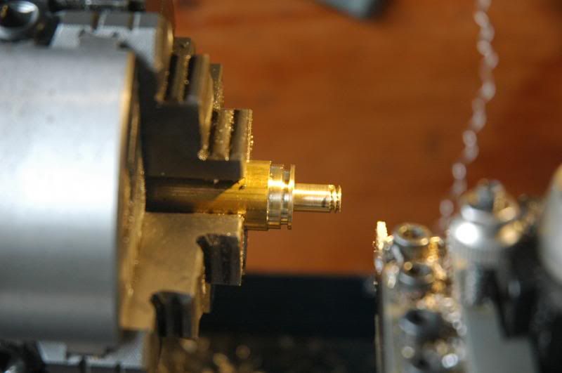
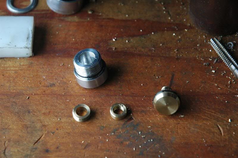
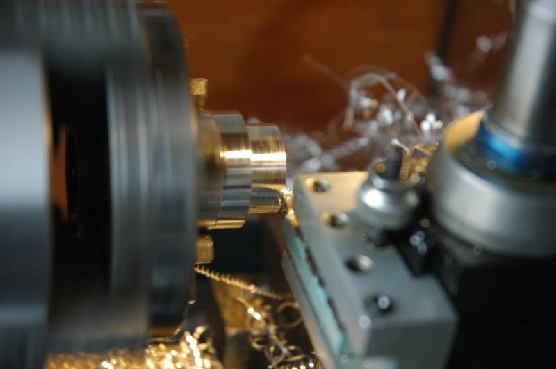
Rechuck the brass about 7/8” further out, face it then turn it down
The left-most part is cut to 14.5mm. The right part will be cut down to 1/4”
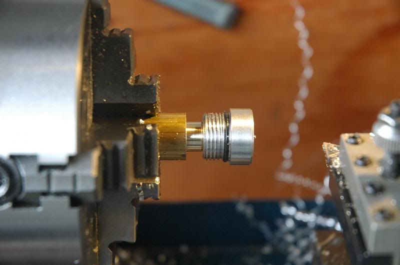
The externally threaded retaining ring slides right on
Mark where I want the threads to end and thread it to 1/4”X20TPI
The internally threaded retaining ring screws on
Taking advantage of the handy retaining ring holder, I cleaned up the flash left from parting
The relationship of the three brass parts and how the tailcap attaches
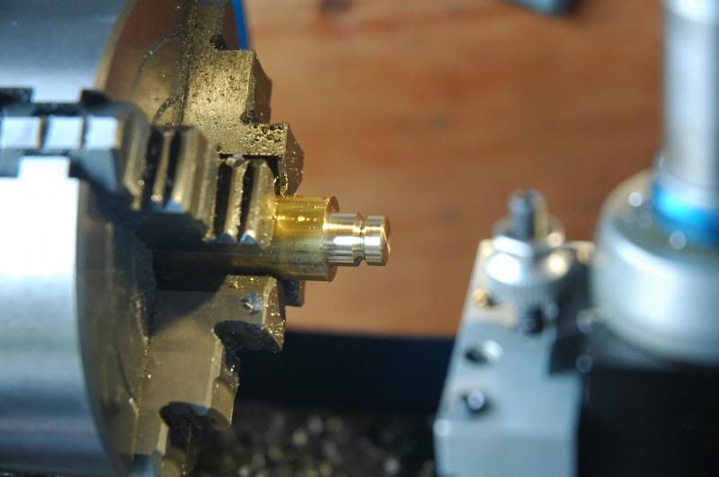
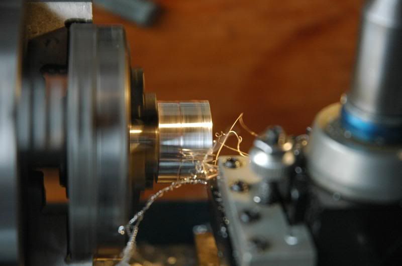
Bevel the sharp edge
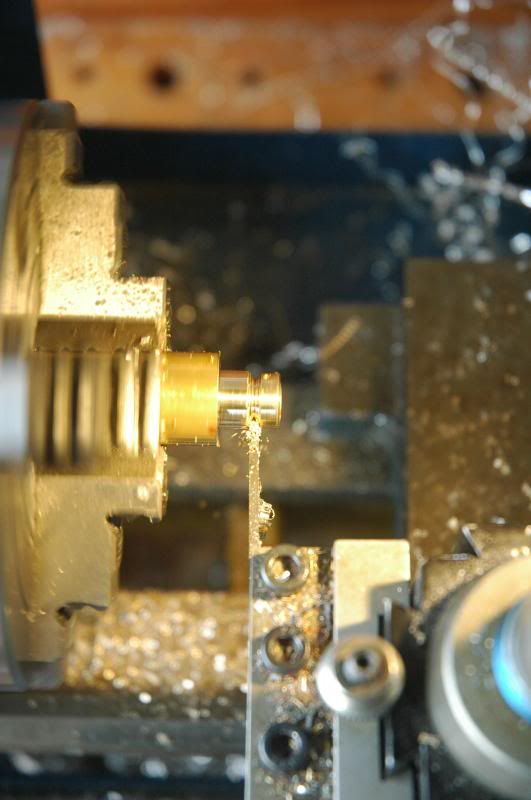
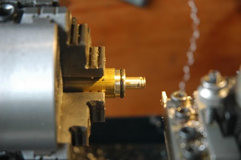
Next, cut a groove for the O-ring using the parting tool and install it
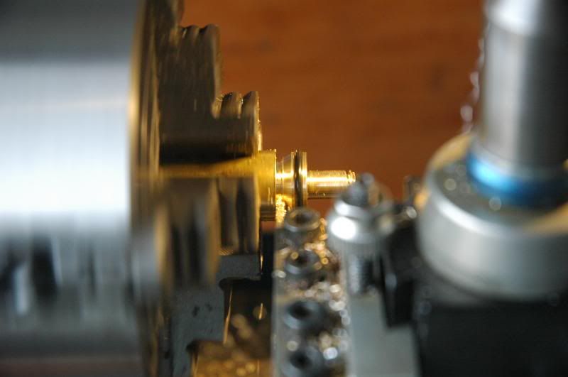
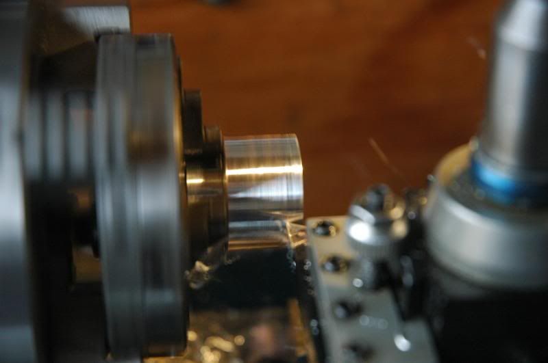
Using the turning cutter, cut a bevel
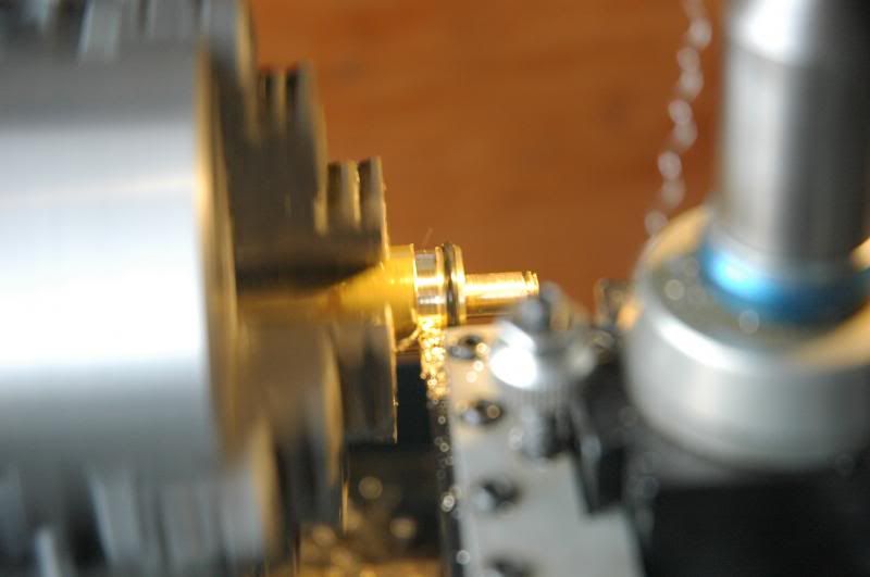
Part it off
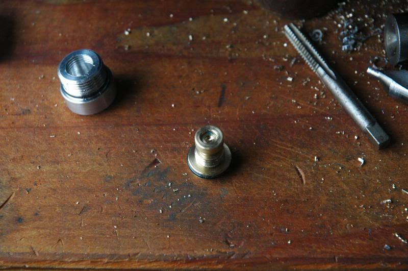
The plunger assembly assembled. The internally threaded retaining ring is screwed on using Loktite
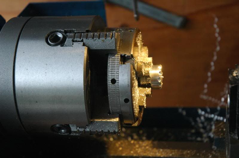
Reposition the mill head assemby at 60 degrees, install the tailcap in the four jaw chuck, then center it on the Y axis
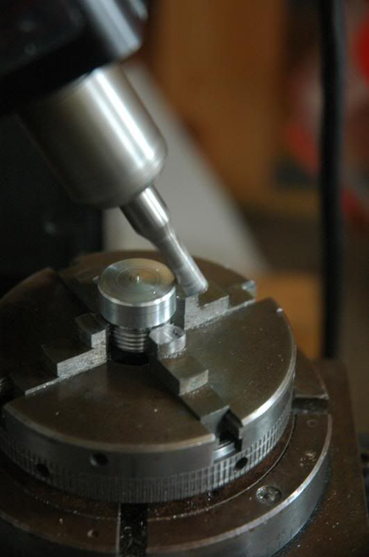
One notch every 60 degrees
Reposition the mill head assembly at 30 degrees, rotate the tailcap 30 degrees and cut another series of notches 60 degrees apart
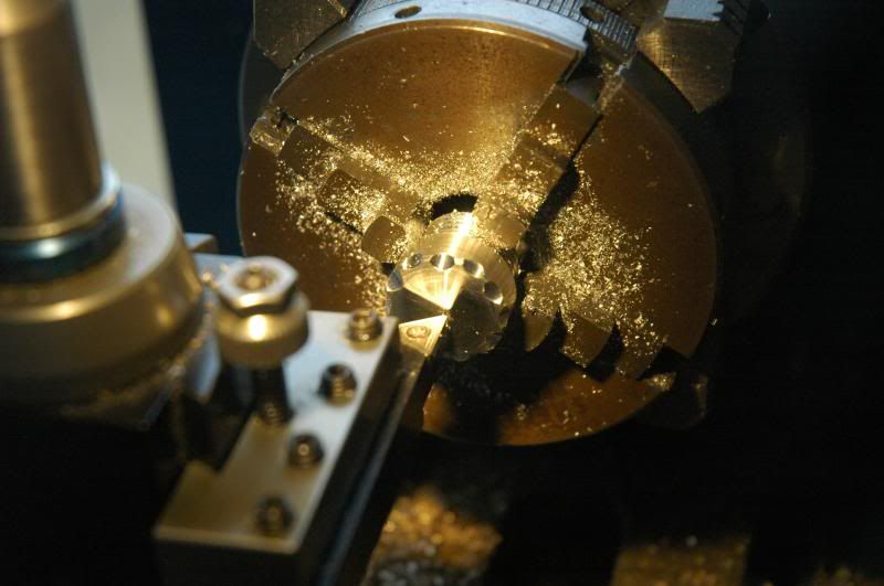
Remove the chuck from the mill and attach it on the lathe, tailcap and all
Face the tailcap. Shiny finish
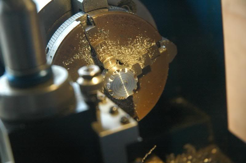
Cut grooves into the face of the tailcap
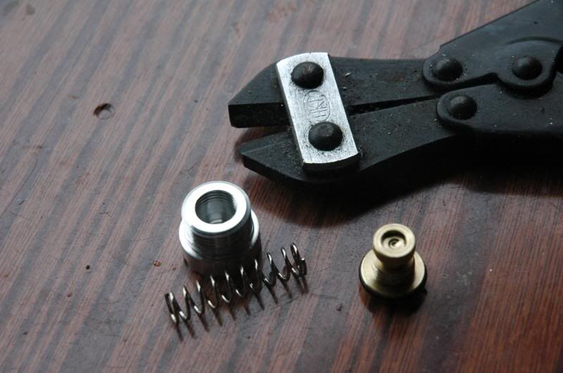
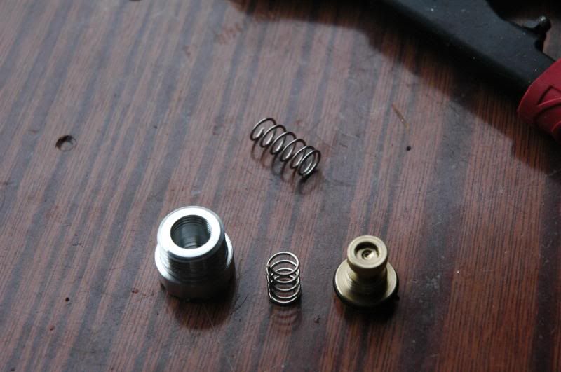
Ready to assemble, but, the spring is too long
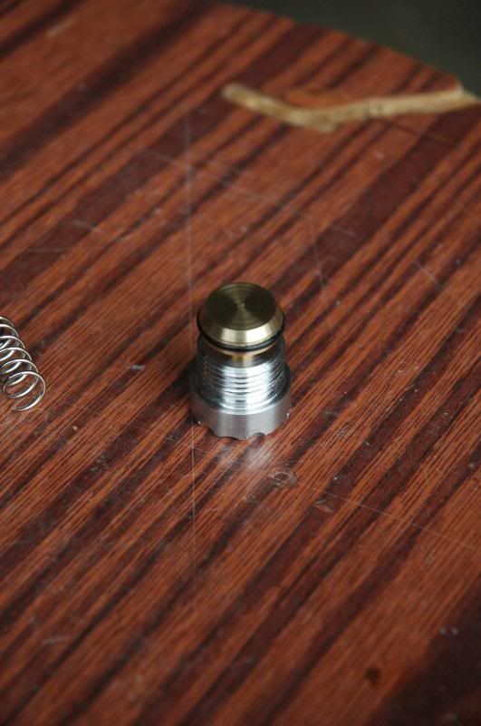
Tailcap assembled showing the fully extended length and the compressed length
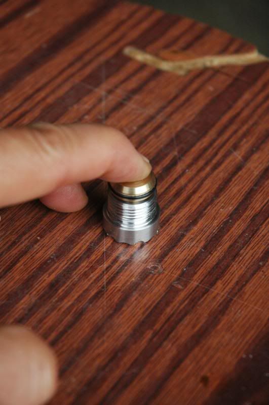
After the last picture was taken I adjusted the spring length and that allowed the plunger assembly to have a longer travel, about 1/8”.
Tomorrow, the head…
4/21 update
After giving it some thought I had realized that I had made a mistake: the diameter of the aluminum tailcap is too close to the diameter of the O-ring and the O-ring will contact the threads of the body. To test this I took a scrap of acrylic rod and made a piece that will mimic the flashlight body. Additionally, I made this because the head is going to use the same exact threads so that the body is reversible.
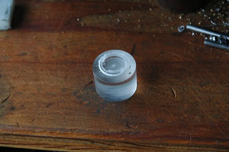
The scrap acrylic
Chucked in the lathe and faced
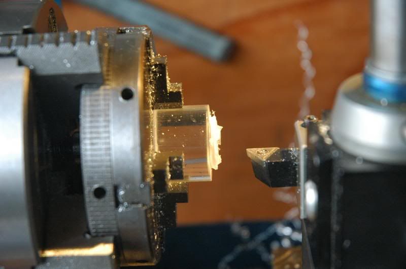
Drilled it, first with the center drill then with a 1/2” bit
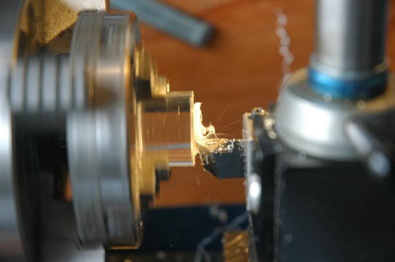
Using the small boring bar, opened it up to 15.0mm
Cut threads until the head fit (removed the plunger assembly for fitting)
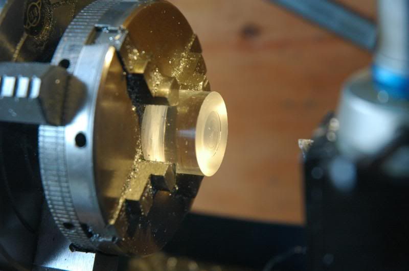
Cut off the end of the threads for the O-ring and flare the end to allow the O-ring to slide in
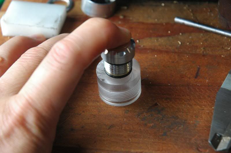
Just as I had suspected, the plunger is too large and the O-ring groove is not deep enough. You can see that I’m putting pressure onto the tailcap trying to force it into the body and it’s not going.
The plunger itself needs to be redone so it’s not a total loss. The remaining pieces can be reused. Since the steps to make the replacement plunger are essentially the same, just using different dimensions, I won’t document it here. Needless to say, I’ll be using a smaller O-ring in addition to the plunger with a smaller diameter. Flying by the seat of the pants has its ups and downs…
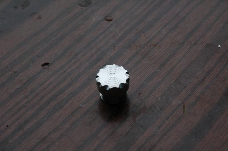
4/24/2014 Update
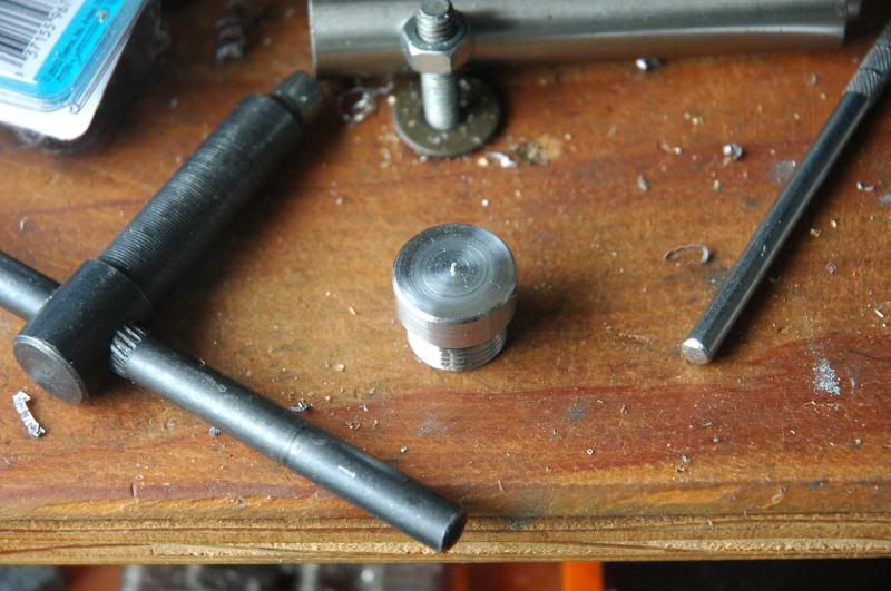
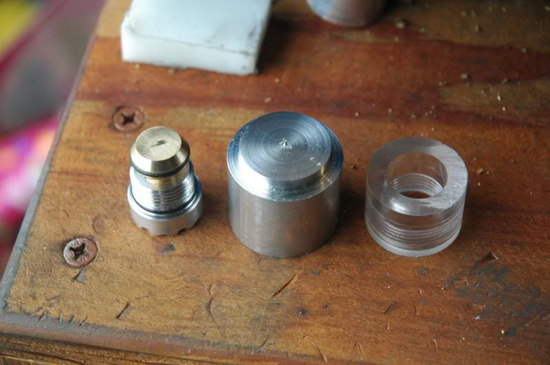
Finished the plunger. It now works the way I had wanted it to.
Picture shows the finished tailcap, the slug of 1 1/8” 7075 T6 scrap that I found, and the temporary piece to test the threading of the head and tail. Mind you, this scrap piece was what was in the chuck while making something else and that other part was finished, leaving this piece of aluminum.
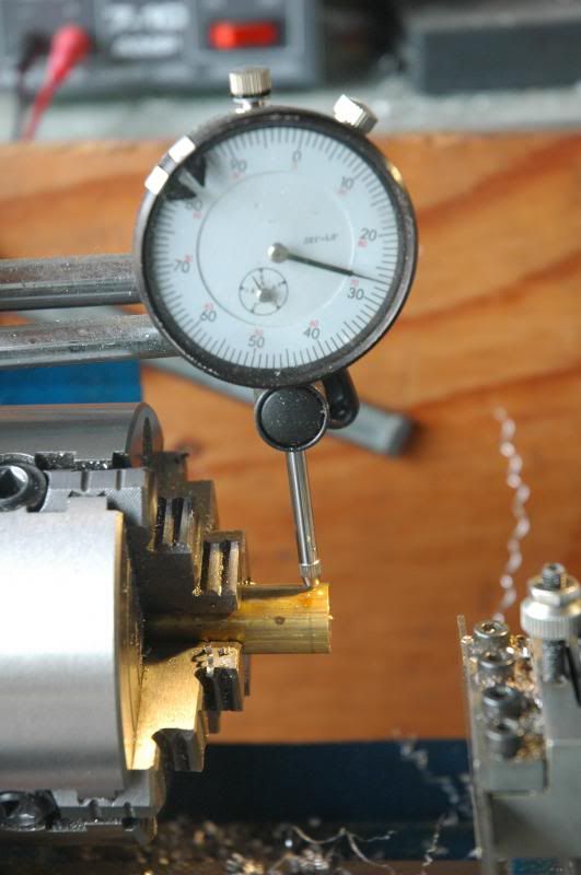
The aluminum is installed in the centering four-jaw chuck that was installed in the lathe. The saw marks on the back of the slug needs to be cleaned up.
It didn’t need to be completely cleaned up just yet. The small contact area where the chuck holds the piece had me worried that the piece would pop out of the chuck so I cleaned it up with skimming cuts and it took quite a few passes to get to this stage and I wanted to cut the other side to get more contact area
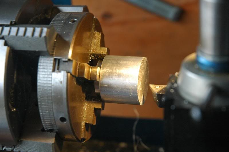
Reversed the piece and started removing material. I centered it around the smaller diameter part
Using the threading cutter, removing the sharp edges
Now that there’s a longer shoulder for the chuck to grab onto I flipped the part again and turned down the outside to match the diameters then turned it down further to 22.7mm. The target diameter is going to be 22.2mm, which coincides with 7/8”
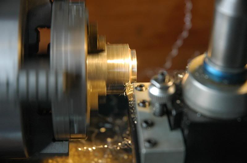
Now that the diameter is closer to where I want it to be, I can finally finish facing it
Rotate the facing tool 45 degrees and cut a bevel
This is as far as I was able to get to today. Tomorrow I should be able to start the pocket for the reflector and emitter. The other end still needs to have the diameter reduced to 16mm, the 0-ring groove cut, threads cut, and the pocket for the driver. After that the positive contact and some other things made to get the head finished.