So please,is there a CW choice?
Not stock
It is V6 3D for the LEDs
Other tints must be reflowed by users
A 7 ledded srk clone arrived today. No time to check it but finally some measuring myself.
it might have been asked before, but i was wondering if there is a general ETA?
Let me again say more about fins. I think deeper and tapered fins will make a significant contribution to how bright it can be run continuously. And I think the whole flashlight culture may benefit from this. I am tired of seeing square fins.
Here is another example of how it is done:
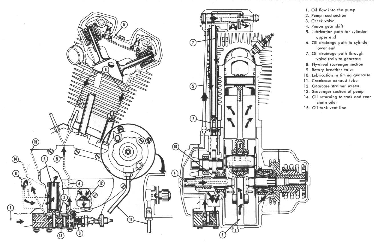
Making the fins deeper is a clear advantage in steady state cooling, at some cost in burst heat because it reduces weight and in price because it requires more metal to be machined off. The reduction in weight is not really a disadvantage because it makes it easier to carry and cheaper to ship. The slight increase in machining cost seems justified by the performance gain. Tapering the fins will probably compensate for the cost of making them deeper. Deeper fins allow more air to flow and more area for it to contact the metal. They improve radiation by allowing the luminance to come closer to the black body level before it is exposed to the outside.
The main place where they can be made deeper appears to be behind the reflector where the drawing shows a lot of solid metal.
The effect of tapering appears to be less well recognized, but advantages are clear from physical principles.
Advantages for convective cooling are that there is more space for the air to flow between the fins near the outside where more flow is needed to cool the air near the bottoms of the grooves, and that there is more metal to conduct heat on the inside where more heat needs to flow. More air is needed near the tips where most of the heat flow is in the air, and more metal is needed near the groove bottoms where most of the heat flow is in the metal.
There is another layer to this that is even harder to explain clearly. The metal is solid and transfers heat by conduction, that is by diffusion with a high heat conductivity. The air has a very low heat conductivity but transfers heat over longer distances by thermal convection (or wind if there is any). The convection is strongest around the light where the air is warm but free to move. It is slowed by viscous friction, that is by diffusion of momentum through the air from the stationary fins. So the ends of the grooves should be wide not just so the heat can be carried out but so the momentum can diffuse in and move the air inside the groove. That is the wide mouth of the groove allows the faster air motion outside to drag a slower but important air motion inside the groove. The bottom of the groove needs to transfer less momentum as well as less heat and can be narrower.
The advantage for radiant cooling is that (looking at it backwards because the process is reciprocal) incident rays more often need to be reflected more than once to escape. Unless the surface is perfectly black to thermal infra-red, the more time a ray is reflected the more is absorbed. With square fins all light striking the fin end can be reflected in one bounce, with tapered fins more or all of the light strikes below the fin tip and may reflect to another surface.
I think that narrower fins are more effective for convective cooling without forced air, because heat transfer through the air is not as good a through the metal. That isn’t as solid an argument as those above, because it depends on numbers I don’t have at hand, but I think it is right. This of course is the big trade off with thermal mass and machining cost. The SK-68 cross section probably shows a design heavily weighted to cost reduction.
This is good, but you need to make few calculations to understand that deep fins will enlarge host area by few % only.
I know only one flashlight with fins that enlarge host are by more than half - lux-rc fl33.
Upd. If you want to leave light in bare hands for long time its area should be at least 15 sq.sm per 1 led watt.
OK Fritz please pm me your email address and I’ll send you some more source files to edit.
I like your commitment and the whole spirit of the Q8 is getting people involved andan oh man what nice cool in depth input we got.
So yes if you can improve something please do!
No
As you can see this is a work in progress.
For example V4 of the driver is now heavily discussed.
For now it is “it is ready when it is ready”, sorry for not being able to give an ETA.
Thanx Fritz. I understand this point more clearly now. It seems the tapered fins are commonly used on motor heads, etc. - it looks very familiar in that picture. From the drawings in the OP, we don't have much room in depth to work with, as with most flashlights. I agree though - more metal/weight is not always a good thing. I've had a SupFire M6 get very, very hot, and took a fairly long time to cool off, but it's finning is also very limited, though it's a heavy, thick body host. It seemed like all that extra metal just held the heat longer.
It is interesting to ponder the matter of cooling fin design, but perhaps air-cooled engines are the wrong direction. Most were designed before the age of CNC. The tapered fins probably are necessary to facilitate casting of the air-cooled parts.
More relevant, there are plenty of designs of finned heat sinks for computers, electronics, liquids, etc.
It turns out that one of the main factors to consider is turbulence of the air passing through the fins:

Interesting as all of this is, cost and ease of manufacture are going to be key for the Q8.
I would not hold my breath for any fin designs that are not easy and cheap to make on the CNC machine.
That said, it would be valuable to test Fritz’s theories and generate some hard data.
Put me down for one Q8, please!
To shed heat it is all about surface area. But the optimum spacing of the fins, if not using forced ventilation (a fan), is about 10 mm for a typical aluminum heat-sink profile. Probably less for shallow fins. And the fins need to be aligned with the natural convection of the air. So vertically.
Talking about something like this: heat sink profile
How this all translates to a flashlight I am not sure.
I am not basing the argument for tapering on engine practice. I am basing it on physics. I don’t think the shapes above will work well without forced air.
That is a good point that the fins should be vertical. Most flashlights have them vertical, unless they are tail standing. But not all:
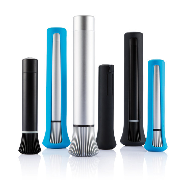
I like these anyway, because they are different. It says “Netherlands Brand”. Some heat sinks are that shape, with the advantage of having more space between the fins as they go out.
Put me down for one if it’s not too late.
My SRK was the flashlight that got me excited about flashlights and modding. I tried to mod it but mine is one of the junky ones with no screw in pill nor any shelf. I improved the driver but the LEDs immediately desoldered themselves. I would love a proper SRK style light.
Fritz, thanks pm received.
I will email you some files tomorrow, thanks for thinking along!
Others will update OP tomorrow yo actualize the interest list.
Pooptoast (lol @ that nick ![]() ) this is exactly one reason for starting the Q8 project!
) this is exactly one reason for starting the Q8 project!
That still makes no sense at all. I can easily turn your reasoning around and argue that light exiting the top of the flat fin is directly leaving the light while light exiting the sides of the tapered fins is more likely hit the fins again and be reabsorbed.
Face it: physics is hard and without the even harder math to back it up, that kind of reasoning does not bring any reliable conclusion.
You’re also still conveniently ignoring that in the worst case (very short fins, as we have here), the tapered fins will have 20% to 30% less surface area. That’s a hard fact and I don’t see how it will help convection cooling.
Tapered fins would add cost. Machining straight fins is one step while tapered would be 2 or 3. The cooling difference would be inconsequential as long as size is the same. Turbulence in finning only comes into play where you have some airflow, which won’t always be the case with a light.
Ages ago I read an extensive tech article about finning on motorcycle engines. A fully machined cylinder was developing hot-spots while the cast one didn’t. The slight difference in surface roughness of the fins was tested by filing the cast version smooth, whereupon it developed the same hotspots. They shot-peened the machined cylinder’s fins as best they could and it’s hot-spots were reduced. Thus IMHO there’s little to be gained reworking the finning unless you add fins or increase the surface area of the fins.
Aesthetics and durability are practical concerns which must also be part of this equation. Given that the Q8 is intended to be an improved version and not the ultimate performance light I think what has been planned will do well enough overall. Those running it all-out for long times without airflow are exceeding it’s design parameters but given the software I think the ramp-down or step-down will compensate adequately. In what will essentially be a low-cost production light it’s looking like it’s going to be unbeatable.
My only concern is that with all the ‘premium’ stuff (compared to similar lights being sold now) we may have a pricing problem. I hope not. And of course I want mine yesterday, but who doesn’t?
Phil
Put me down for one too, if it’s not too late.
Not too late, we have a long way to go I fear ![]()
But one thing I’ve learned about BLF lights (if the BLF A6 was any indication, that is): the longer the wait, the better it is.
And I gotta say I get off on seeing smart people dedicated to just doing something damn better. It’s awesome, and contagious… you can feel it.