Q8, PMS SEND TO THOSE WITH ISSUES BLF soda can light

I got some homework to do. I'll go thru our spec list this eve and see where we stand.

Just to update that list for fixes:

Correct XPL V6 3B 3D LEDs

Little larger oring at the lens - might be able to stretch it out, gotta see

Good finish of inside of tube

Latest Narsil

Maybe another FET, maybe

Things are better:

Stainless steel bezel

A true Narsil driver

double springs

lost the retaining ring but we do have screws

BLF Q8 labeling

Other things to note:

  • tube no longer LEGO's with other SRK's, but there were issues with that anyway
  • new one is 2 mm shorter (good)

3D

(edit: Tom beat me to it)

To really test thermal compound, you need to put it between a heat source and a heatsink. Then, with controlled power in the source, measure the temperature at some relevant location on the heatsink for various power inputs. While current through a device does have a temperature dependence, I am not sure this is a preferred evaluation technique. Mapping the device curves for current could be useful. But how much of the observed effect is in reality a temperature feedback loop within the semiconductor device. And then again, I could just be perusing angels and pin landing sites.

For picking a compound, Google some of the PC overclocking sites or just general testing sites. Be aware, some compounds also conduct electricity.

Big Big thanks for that!!! I am searching for a FW with Ramping (for clicky lights) for a long time. Hope that it will be available soon! Even if i have to change the tiny13 with a tiny25 to get the best result.

@Tom E
Can you see which FET they used on the latest Proto Driver?
Is the polarity protection ring on top of the screws glued in? I have to say i do not like glue in a light! And i absolutly do not like countersunk screws to secure a driver!
It looks cheap and the slightest misalignment between the holes in the driver and the holes in the light could warp the driver. Also if you are using countersunk screws on a PCB you can easily crack the PCB if you are not really careful with tightening the screws. I really hope that they find another solution!!!
It might be ok for most of the people but it is not really mod friendly. Sure i can find a mod solution (glue in a new driver. . .) but i would only use glue as a last resort!

Yes, we know what FET it is and we will ask them for a change on it. It's the NXP PSNM3R0-30YLDX, so not the better one. Better one is: PSNM2R0-30YLDX.

Yes, the polarity protection was glued on, but not badly. I used the pry tool shown in post #5314 to get it loose with some minor damage. We are discussing options there with them.

Agree, not the best way to go w/screws there, but they seem committed to it, being that the battery tube and head were designed for it. For modding, a replacement driver could be press fit with no glue - this is what I usually do, but couple dabs of thermal epoxy could work also.

Oh boy -- driver diameter is 47.6 mm, slightly bigger than most SRK clones, and our BLF Q8 (OSHPark) driver at 45.86 mm. HQ's driver is 46.23 mm with wider tabs to sand down.

Oh, it’s already available. It’s a bit off-topic here though. Check the recent posts in the firmware thread in my signature for more info.

I don’t mind the screws as a retention mechanism: probably easier to put back in than a ring and as long as it can all be taken apart, it’s ok. Future drivers can certainly be designed with the holes.

I wonder though, how is the ground connection achieved? Is it through the screws only? Or does it depend on the tube screwing in until it contacts the driver? It looks like the driver sits on an anodized shelf so not there for sure. The screws don’t seem like a very reliable way to connect to the driver PCB, especially at high current as there’s only a tiny contact line between the copper layer of the PCB and the screw head.

If it depends on the battery tube contacting the driver, this seems bad too. It’s subject to driver PCB wear and very sensitive to tolerances (tube too short or driver too thin = no light).

Or am I missing something obvious? I’ll admit I haven’t taken apart that many lights but this seems like something worth looking at more closely. It’s my only real concern with the screws.

I think the driver contact with head does not matter too much because the head ground path need to go through the anodized tube threads which need for lockout. So the only route for ground is the tube’s edge to driver.

Question: Since Thorfire has included double springs for this version, is it still advantageous to do a spring bypass? Or are the gains minimal?

Double springs aren’t as good as a bypassed spring, but they’re a lot better than a single spring with no bypass. You could probably improve it a little with a bypass, but it’s a matter of diminishing returns and the extra spring makes the bypass harder to do.

So, this makes it better by default but a little harder to mod. We get like 80% of the benefit of bypassed springs, but that last 20% is a little less convenient.

If double springs behave like two single springs, the resistance will halve, while a bypass will make the resistance in the order of 15 times less, that is quite a difference. (see my ‘springs!’ test via the sigline below)

But if upon compression the two springs touch each other in multiple places, it could be that resistance is lower than expected.

Also, I have seen in the X5 and X6 lights they used quite thin wire for the double springs, that makes the advantage less.

As with the turning on to check if it works I guess with the springs the Pareto Principle goes :slight_smile:

Thank-You for the quick answer ToyKeeper Djoz

Hmm… what to think…
At this point its looking like:
Priorities From High to Low

Best Stock Light
Safety
Modification Ability

ThoreFire has definitely switched gears for both good and a bit less than good.

Whats that principle Miller?

Sounds reasonable.
I can’t see whether the issue is a real problem from the photo provided but anyway, my Roche m170 has good led alingment, my way cheaper SRK clone has good led alingment. I see no reason why Q8 should be different.

TF anyway is going to sell Q8 under their brand afterwards and people definitely won’t be happy with that (possible) drawback. Possibly someone will face an issue while modding after LED reflowing, etc.
I think this should be at least addressed to TF and then check their reaction.

Pareto Principle
20%/80%
20% of labour achieves 80% of the work
20% of clients will earn a company 80% of profits
20% of clients will have 80% of problems

So double springs being 20% of work and trouble compared to good spring bypass will gain 80% (while some want to go 100% and need to fo a bypass thus putting in allbtge work)
Switching the Q8 on makes TF spot 80% of issues, a very in depth long lasting test procedure would elevate that but at a high cost.

Sorry, had to catch up on some sleep.

The contact to ground is made via the battery tube's top edge contact to the drivers ground ring. The nice feature about this light is the battery tube's threads and o-ring fit nicely under the head, as it threads in, so I don't believe tolerances and wear will effect this ground contact negatively. There's no hard stop for it threading in, another words. Also nice it has a simple mechanical lockout, but that feature could wear out in time. The anodizing is not high quality. Dang - haven't taken close-up pics of the threads yet, they are supposed to be square, but if you don't have quality anodizing, I would think the wear will eventually break the mechanical lockout.

The bad side? Well, I mentioned before the driver's diameter is wider than normal SRK drivers, and the battery tube's top edge is thin in order to clear the new polarity protection plastic cover added. So for driver replacement, stock SRK drivers might be too narrow for ground contact - it's a risk, didn't try it myself yet so not sure.

I re-assembled proto #3 last night, stretching out the lens o-ring seemed to work out to make the assembly easier. Proto #3 that had the weaker #'s seems to have improved now. The screw holding down the reflector was definitely loose before, now it's tight, and I think the LED's look much better centered.

The thing I like a whole lot about this light is the low profile LED alignment pieces. The cheap SRK clones are awful - thick base, high sides - these are really low profile in both dimensions, which I believe translates to more LED in the reflector, more light out.

Here's what I'm talking about.

One big copper DTP MCPCB, best setup, appears identical to proto #1, accept for the screws:

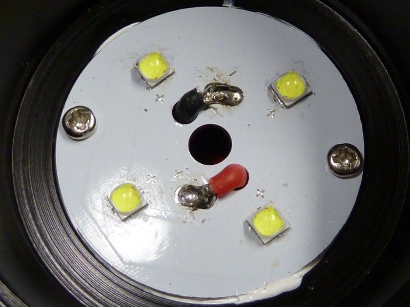
This is where they made some changes - same reflector, same dimensions (18mm high, 51 mm wide, 23 mm I.D. reflectors, 7.05 mm holes), but backside machined differently. The screws were changed from flat head to pan head - an improvement because pan heads will not apply force to potentially buckle the copper MCPCB as flat heads would if hole alignments are not perfectly set. To make room for the pan heads, they drilled out holes. They also made the center hole slightly wider to properly clear the solder pads.

The low profile alignment pieces. Proto #1 used similar ones, but they are jammed into the reflector, partially broken, as if they didn't fit right. These are about a perfect fit.

Close up view of the side switch. The 4.7K resistor is way too low for these green LED's (2). The parasitic draw with these on is 0.4 mA, and with them off is 0.038 mA. The LED's are very bright, bright enough to light up your path in pitch darkness. I'd suggest about a 10K, and that should lower the drain to about 0.2 mA

I've been saying the LED's that came in the prototypes were not acceptable - CW with hints of blue and green. Thinking maybe like a 1S or 1B tint. Here's comparisons - 4X SRK clone with XM-L2 U3 3D's on the left, proto #2 on the right. First a lower output level:

Higher output level:

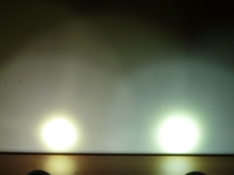
These wall shots are about what I'm seeing. Did a bunch of camera settings checks to get it matching pretty close. Maybe the blues and greens are a little more emphasized in the pictures, but they are there in real life.

If it turns out that the driver dimensions plus screw hole fixation of proto2 will make it into the production Q8, with 1000+ Q8’s around I can see modders adapt their Oshpark designs for the screw holes and new dimensions.

I kind of like the way the proto2 board is fixed with screws (although would like to see the plastic ring screwed together with the driver board), but of course it would be more convenient if the Q8 uses the standard dimensions of SRK boards.

Thanks!

hmm that driver size can we see that as issue?

Ah so first screw ledboard to shelf, then reflector to ledboard, then place driver.
Makes sense and two screws for the ledboard, nice.

Good picture to show the 3*D* :wink: tint.

Do you see any diffence in switch setup on the two latest protos?

Thanks for the new pics Tom, so with the two screws we have good clamping force between ledboard and shelf! I really like how the construction is now, it was not how we figured it beforehand (reflector screwed against shelf with the ledboard sandwiched in between), but this will do the job well!

Is the ledboard the same as proto1?