Q8, PMS SEND TO THOSE WITH ISSUES BLF soda can light

I do like the pan head screws better.

For driver size, dunno - the slightly bigger size makes it more complicated but I'm liking this design. A retaining ring has it's merits though

For the switch, they fixed up the mounting for sure - much better. Didn't take apart proto # 2's switch, but proto #2 activates too easily (longer center stem?) and proto #3 activates too hard (shorter center stem?). The stem in the rubber switch is pretty short in proto #3. There is slop in there for positioning the PCB while you tighten down the switch. This could also be the problem, and might explain differences if proto #2's switch PCB was not centered properly.

I'm definitely concerned about this now the more I think of it - too many things can go wrong in production assembly, and the feel of the switch is an important aspect of a UI based on ramping. I'll have to take some pics to show this in more detail, and take apart proto #2's switch.

Yes - the ledboard (MCPCB) matches up identically with proto #1. Didn't take them out to measure thickness, but everything else matches.

I bet that the Thorfire engineers are surprised how well the Q8 construction works.

The BLF way (everything parallel, massively beef up the complete current path from battery to led) is not the solution that high end manufacturers choose (you see series constructions everywhere to keep the amperage down), but it does pay off bigtime!

Ok, not having a hard stop should indeed mean no tolerance problems and good contact. I don’t know about wear though. Do you feel like screwing and unscrewing it a hundred times or so? :slight_smile: Just enough to untighten it should do and I think any really major issue should come up by then.

It looks like we’re getting really close now. Congrats everyone!

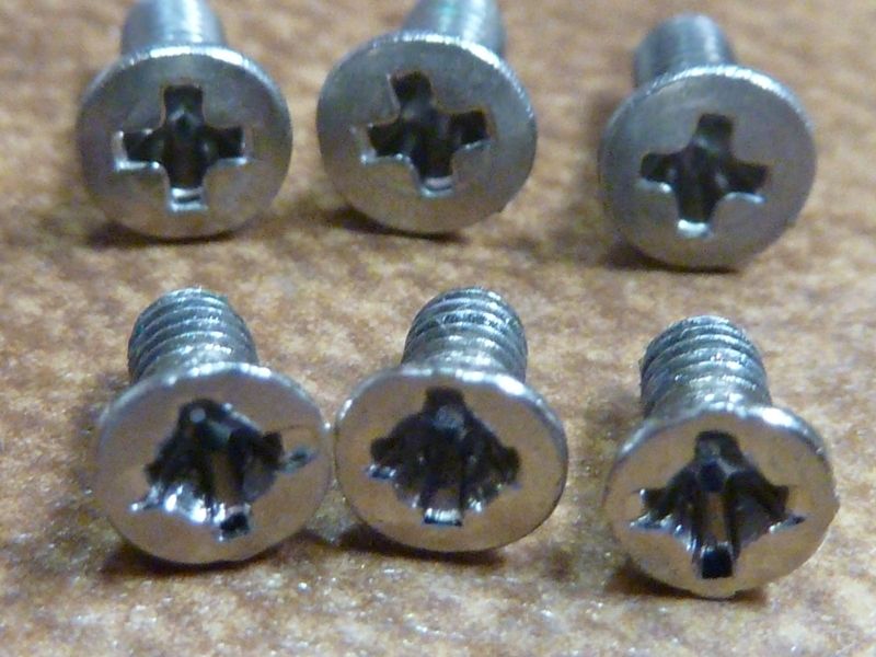
Manufacturing reality input here - a screw, even two screws, are a LOT easier to install than a very large diameter thin retaining ring. And by easier, I mean cheaper, faster, and more reliable good installation. IMO there is a very good chance that the decision to use two screws was a manufacturability decision.

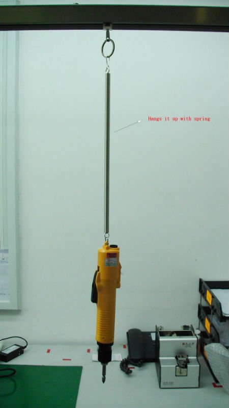
Two screws requires a (hopefully) Torque controlled electronic screw driver, and a magnetic bit, that’s it for “tooling”. Thorfire certainly already has that in house, and it will probably be about 3-4 seconds worth of process time to shoot two screws.

For a retaining ring of that size you either have to 1) slow down production to allow a worker 20+ seconds to fiddle with that retaining ring, which is an ETERNITY in manufacturing or 2) create custom tooling/fixturing/jigs to pick up the ring properly, align it properly, drive it properly, and torque it properly – and it still won’t be faster than two screws. All of that equipment costs time and money to design and build, plus it must be maintained during production otherwise it will cause more issues than it solves.

We all know how fiddly retaining ring can be to get them installed properly, and larger diameter ones are more difficult. Difficulty = time = money in manufacturing. Also, difficulty = quality problems and scrap cost when you cross thread them (and you will). Cross thread the retaining ring and you probably need to scrap the machined head and eat that cost. Cross thread a screw and you just run a tap down it and re-shoot the screw – a 60second rework process.

Other downsides to a retaining ring from the design POV: you either have to do another machining process on the head to create a second set of threads (cost, time, complexity), or use the same threads the battery tube uses, which risks the battery tube affecting the torque on the ring. We know that constantly screwing and unscrewing tailcaps can loosen switch retaining rings, the effect would be much more significant with a larger diameter ring.

And from a cost POV it is also obvious - two screws cost next to nothing, easily less than one penny. A brass retaining ring that has to be designed and manufactured specifically for this light probably winds up costing $0.20-$0.50 each (I’m a QC engineer not a buyer, cut me some slack on the wide range). That doesn’t seem like a lot to you or me individually, but it is a lot when you are making thousands of units that you are trying to profit from.

To me it’s really easy to see why they would use two screws instead of a retaining ring – unless we are willing to press the issue (and potentially pay for the retaining ring either directly with money, or by indirectly by sacrificing some other aspect), the screws are the better design for Thorfire.

With this “screw” system for the driver , 4s or 2s setup with TA’s driver is a bit tricky … Anyway , if it’s not difficult for them , retaining ring seems to be better , for me at least . (just my 2c)

Because of my lack of real hands-on experience modding flashlights, I’m not certain about how critical each of the designs on the latest prototypes weigh in the “really nice working flashlight for $40” vs “mod machine” continuum.

I know that one major emphasis on this light is modability, but with it’s out of the box performance, I wonder how many of the 1000+ lights will realistically ever be tweaked.

In a perfect world, there would be a retaining ring and no screws and better compatibility, stricter construction tolerances and the correct components, but I wonder if TF will be willing to make some of these changes for the modest price set in the first post.

I don’t want to settle for much less, especially with the potential for a truly amazing light, but where is the line going to be drawn for certain wants and needs, especially given that more and more changes will result in longer (maybe much longer) wait time.

I’m not certain about where I stand in this right now. I signed up for two flashlights with the idea of keeping one stock and hot-rodding the other. Just want to throw some of my thoughts out there for consideration.

If the production Q8 has the performance of proto2 , there will not be much hotrodding leftover to do :stuck_out_tongue:

Unless you go into the trouble of a total rebuild for XHP50.2’s of course.

I think for the battery contact, its better with a driver retaining ring. I think the drivers ground ring can wear off after some hundred lockouts.
A copper or brass ring at the driver ground ring would prevent it and the screws can hold the driver furthermore.

I think for the screw which holds the reflector, its not possible to use it with 4 custom MCPCBs. Modders have to use a longer screw and a stripe of metal with a hole, to screw the reflector against the shelf (base of the mcpcb) of the flashlight.
Three wholes in the shelf instead of one big would prevent this.

xhp35 hi :heart_eyes:

Lot of good input there, specially from sac02. In reality though on the China production lines, I've seen a lot of stripped head screws. My super 16X had them all stripped, mangled - had to replace them all, so a proper torque driver was either not used or not correctly used. Probably the screws are bad as well.

Replacements above, originals below, and this was in a $90 UltraFire (false brand, effective no-name) light.

But, you definitely have me convinced the screws is a cost reduction effort - very good explanation there. Thanks sac02!

Where I contract at (Biomed industry), we have "work cells", all designed, laid out for convenience, reduction of motion, all for time saving and quality considerations taken into account, and yes, all air powered tools hanging down on pull cables, but no torque based air tools - I was told by the production manager they were too expensive, plus need regular calibration. We are not high production though - typically 5-50 units per month. They use torque wrenches, but only limited use. Hhmm, I should take/post some pics because it is interesting... I'm afraid though there's not much of this level of thought and expense put into most work cells in China, from pictures and other info I've seen, heard.

Sorry, if I said strip (did I say strip? I’m to lazy to go back and re-read that wall of text I posted, lol) I meant cross-thread. If they crossthread a screw they can just run a tap chaser down the threaded holes in the head and refurbish the threads well enough for a joint that isn’t a safety critical joint (we have lots of those safety critical joints that we won’t allow thread repairs on cars, not so much on flashlights, lol).

If they strip the head of the screw, yes they should remove and replace it with a new screw, there’s no way to rework that. But that depends on them having decent QC standards and practices. If they don’t have good QC, well, all that maters is that they got it to seat, right? They only said to “install” the screw, nobody said anything about not damaging it in the process… :innocent:

Better add 1 for me, for a total of 2. I’m # 271.

You got a good point there. This is common in many lights, but with most lights, batteries aren't replaced at this threaded joint while on an SRK they are. Hhmm, reflow a brass overlay ring? Yikes. Gets back to why they did this - if pure cost savings, this is where the price is paid.

He also brings up a good point about the reflector being screwed to the mcpcb making it almost impossible for modders to mount the reflector with individual stars in the case of say an xhp50.2 swap.

Having the reflector threaded via the 2 outside holes and sandwiching the mcpcb in the middle would make such a mod much easier, including alignment of the LED’s.

Sac02, thanks for the insights
I gladly let them cut this corner and we will send that pic of Tom with the busted and good screws to explain that care must be taken when installing the screws.

Only issue with the two holes and driver is that either osh designs must be adapted (two options see below) or a dab of glue must be used when using a different driver
Option 1 adding tabs to file to the right size for a press fit
Option two screw holes with so much real estate this does not seem extremely hard, even an outer ring of 7135 chips can “wave” around the hole creating space for one or two extra maybe.

About polarity protection ring, I lean towards leaving it as is but ask for much less glue one a little spec so modders can take it of easier.

I kind of think we have a reflector, ledboard, driver, safe polarity protection, thick brass ring that work together
Based on our designs and practical choices.
Remember, when we started this a fat brass ring like this was not expected yet it is there.
Remember when we started the idea of one big copper DTP ledboard was a mere dream not expected to come true yet it is there.

Yes this config might make modding a bit harder, but honestly, the driver with Narsil is so sweet for a LED swap this will do just fine leaving only 6 and 12V LEDs as serious mods, people starting those surely can deal with what comes stock right?

All true, agree. Work-around could be adding a round plate on the underside of the shelf, inside the pill cavity, and using a min of 5-6 mm longer screw. The shelf is 4.92 mm thick, 16.5 mm center hole, so a round plate of 18-22 mm or so diameter, holes for the wires, center hole for the screw would do it. Must be fairly sturdy, thick alum or thinner SS - not sure.

I'm pretty sure the shelf is thinner now that it as in proto #1 - gottat check notes and/or pics. 7 mm rings a bell.

View of inside the cavity:

Proto #1, though all cleaned up and naked, top view:

Dang, the more I look at the proto #3 pic above, the more confused I am at what I'm seeing. Almost looks like a copper plate under the MCPCB, and the anodized alum shelf is even thinner. I measured 4.92 mm thickness simply by the top of the shelf, as seen here, to where the gauge made flat contact... Hhmm....

A reason to want a different driver in a single die situation is the new low voltage leds like Nichia 219C, XP-G3 and XP-L2. Their voltage is so low that you may want to regulate the current with a lineair driver instead of direct drive.

This issue with this for a mod where you want to glue the mcpcb’s in place and have them centered is that if you put together a backside mounting plate it would be extremely difficult to ensure it was perfectly centered, meaning that the whole assembly could be off.

Not impossible to work around but not ideal by any means.

This is a good point but then I suppose people can go old school and glue the driver in place as well. As long as there is a lip to hold the edge of the shelf this should be possible.

What about this? If you’re going to ask them to change something, why don’t you ask them to reverse the direction of the two screws holding the MCPCB down? Thread the back of the reflector for those two screws, drill out the holes in the shelf (leave un-threaded) and run those two screws from the back of the shelf through the MCPCB into the reflector!