Yes but one has to mod it in oneself ![]()
We did say wherever possible the most mod friendly solution would be picked.
This is Version 1 and we are going to mail it to Thorfire tonight so their EEs can look at it.
Thanks keengeorge!
Yes but one has to mod it in oneself ![]()
We did say wherever possible the most mod friendly solution would be picked.
This is Version 1 and we are going to mail it to Thorfire tonight so their EEs can look at it.
Thanks keengeorge!
Nice work PD. Looks amazing. Now I just wish I understood how it all works. ![]()
In for at least one, thanks
Peetz
Looks nice. Nice board layout. Please put me down for one NW as well.
“BLF premium edition SRK type monster flashlight”. :smiling_imp:
Well, that one sounds quite goody!
Please put me on the list for one of those.
Macs
Add me to the list please.
+1 for me please!
And driver design emailed to Thorfire!
Well, I didn’t get in on time I guess, but I’d like to ask about the driver design. Is the layout, placement of components and quantity/layout of vias going to be sufficient for the current draw? Mostly, I’m thinking about the LED+ pour with the vias in the shape of ‘Q8’. Is that number of vias enough for all the current draw? It looks like there is plenty of room for more vias there, so why limit it? And, if possible, a very thick pour would be nice.
That number of via’s should be more than plenty for all the current that you want.
Well, not that I’m personally gonna push any limits, but we did say mod friendly design, right? What if somebody wanted to put in 4x SBT-70’s at 10+ amps each? :smiling_imp:
I dont think the fet could allow more than 30 amps . Just my thought…
Mod friendly, hhhmmm. Within reasonable means.
The simplest way to remove any doubt would be to fill the vias with solder, or drill your own holes and fill them with copper, soldered in - simple mods, if vias is your concern. As a modder, there are far more challenges than those vias for high performance, and to tell you the truth, I for one probably wouldn't touch that area, since filling in the vias is probably not a measurable difference.
The SIR800DP FET is spec'd to handle 50A continuous drain, as listed here: mouser.com/ProductDetail/Vishay/SIR800DP-T1-GE3. According to some BLF posts on it, it handles high amps very well - stays cooler than any others we've tested. Dale and I swear by them, but RMM also commented favorably on it. This is why I think it's great for a multi-emitter, high amp light. The old style SRK drivers, with separate driving circuitry per LED is not necessary with this type of FET. Mostly it's an overkill for single LED lights, in typical ranges, up to 8A or so.
Ohh - cross posted, but +1 with djozz below. I ordered some SIR404DP's - they have a slightly higher max current drain spec of 60A and lower resistance (http://www.mouser.com/ds/2/427/sir404dp-247417.pdf vs. http://www.mouser.com/ds/2/427/SIR800DP-244520.pdf), and comfy noted they could perform better than the SIR800DP. The SIR404DP does cost a bit more though, and, of course is untested in an 85 based driver, as far as I know. That is until I receive them 
Even at 40A I see hardly any resistance caused by this number of via’s.
It is a BLF-thing: if twice the thickness/weight/number of anything gives 0.05% performance gain, people say yeah, let’s go for it ![]() But design-wise it is not the way to go.
But design-wise it is not the way to go.
Well, I don’t know enough about driver design, so I ask. Thanks for answering! If you say those vias are enough, then I’m satisfied. Like I said, I’m not the one who’s going to push 40A through an SRK anyway. ![]()
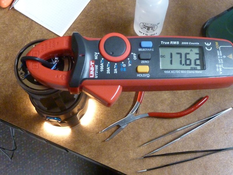
Also fyi, I've only reached as high as 17+ amps in an SRK clone mod, but plan on doing a bit better than that. If 20A is hit for a 4 XPL full mod, I'd be real happy.
David input is much appreciated!
Well, I was looking at Richard’s BLF SRK FET driver V2 to see if I could recognize similarities/differences with this design from PD68. I did see some differences. One is that Richard includes LDO option on his board (pads for components). I know we’re not going to need LDO, because we’re using ~3V emitters. But, if the layout could be designed so that LDO can be shoe-horned in by a serious modder bent on making 2S, 3S or 4S drive, that might be cool. Maybe just tweak the layout of the traces, so that the mask can be scraped to reveal pads for LDO components. Is that possible? It shouldn’t add to the cost of the PCB’s, right? And, if it’s covered with mask, it won’t make anything difficult for Thorfire’s assemblers or testers. Once again, this is not anything I will use. I’m just trying to cover all the angles for the benefit of others. :innocent:
Sharpie about your short concern
I tested it in all my SRK type lights.
If there is a flat base the button top is supposed to make contact the wrapper of any cell prevents a short.
So only if cells without wrapping or very torn wrapping is used there is a risk.
On a flat surface 100% on the wrapping around the base is preventive and on a elevated ring less so the cheaper to make ring-less driver design is actually safer!
Also cells with buttons are do clear in what the plus and min poles are and so easy to spot if are placed wrong thus some with button in view other with the flat part.
So I don’t see much danger here.
Ohh yes, we carefully reviewed your list - great input!! Wish we could have gotten some of these things in for the first go-around, but also some imply complex enhancements we can't handle right now. An MCU with a lot more I/O pins (Tiny84), or method of pin sharing would be required. A lot has been developed, but not all shared or completed, so some of these advanced features can't be accommodated at this stage. Dunno if it's weeks or months away, but we can't plan on it for now, and I'm more than bizy on the firmware enhancements.