Recoil Laser Searchlight Build - XR10 [WIP]

Welcome everyone to my new searchlight build :slight_smile:

I have been away from the forums for several years since my last build, the SyniosBeam, but have returned with some newfound inspiration to build another superthrower!

The goal for this build is to improve on what I learnt during my last project, which was a liquid-cooled recoil reflector LED build achieving close to 5k lumens and 10Mcd.

These are the goals for this build:

  • Recoil reflector (but this time glass instead of electroformed, for more precision and rigidity)
  • Laser-phosphor (LEP) light source (going for intensity over lumen output this time)
  • Heat pipe passive cooling (no moving parts, fans, or pumps)
  • Full billet aluminum construction
  • Glass AR-coated front lens
  • 4 or 8 high capacity 21700 cells
  • Built-in USB C fast charging

The reasons for going with recoil reflector this time again is for the following reasons:

  1. The 220mm diameter reflector only costs ~$1300 CAD while a 150mm lens would have cost me $3500 CAD and resulted in less area and therefore lux
  2. The recoil reflector results in a clean beam with no chromatic aberration (lenses will have a slight rainbow effect as the red light bens differently from the blue light)
  3. Recoil reflectors are cool and I can make the flashlight flatter instead of longer

So, based on this, I began the design in CAD.


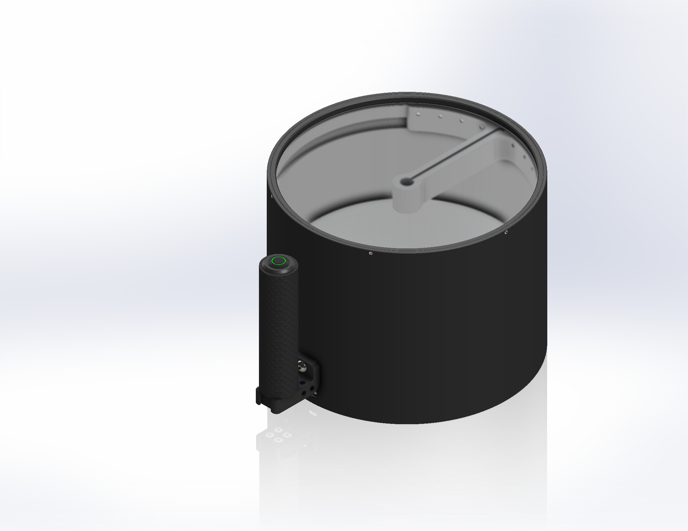
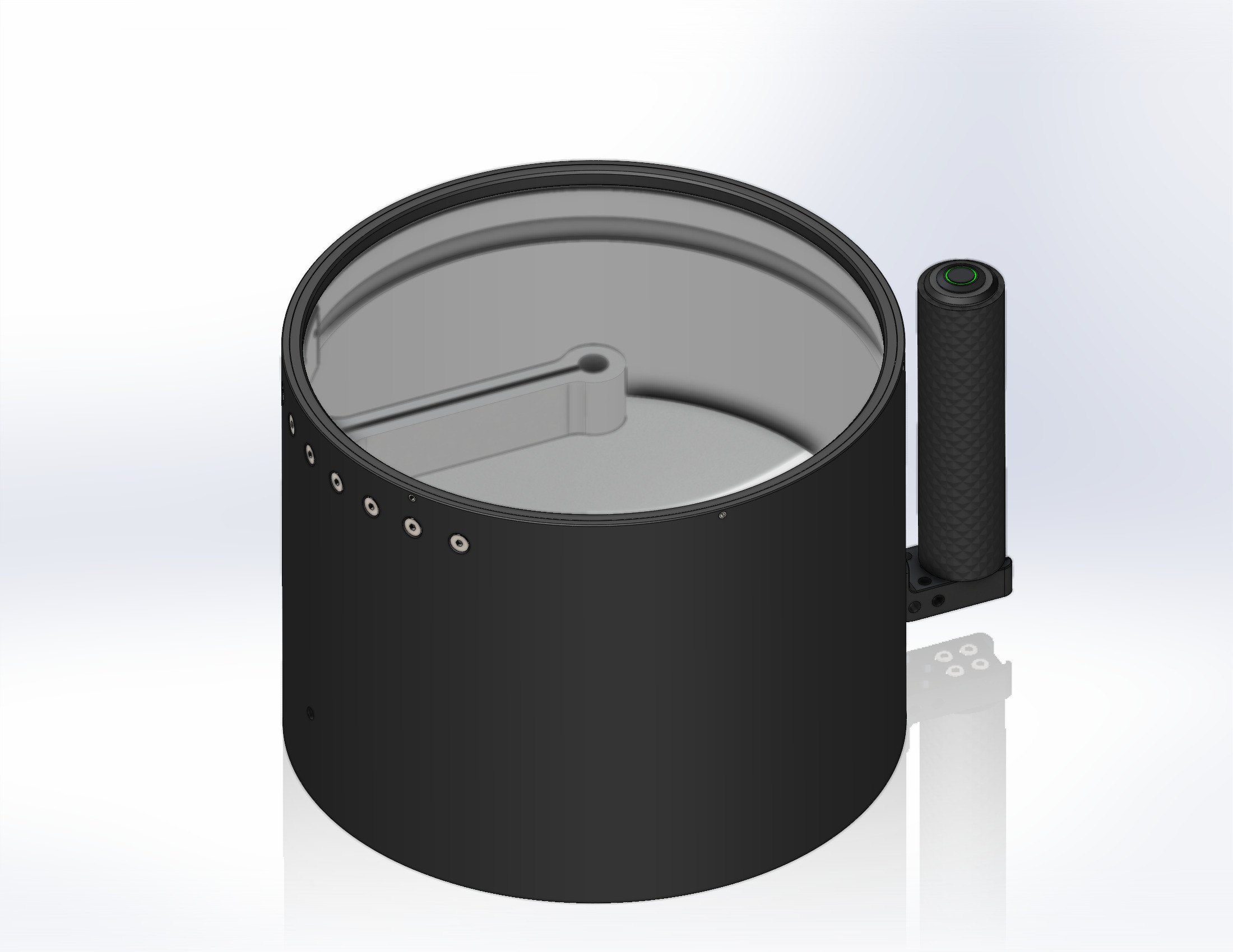
It is a 240mm diameter, 180mm height (4:3 radio) perfect cylinder, with only the handle protruding from the side.


The handle is an off-the-shelf camera top handle from Smallrig, but this specific model is discontinued. A latching push-button switch is installed at the front of the handle.


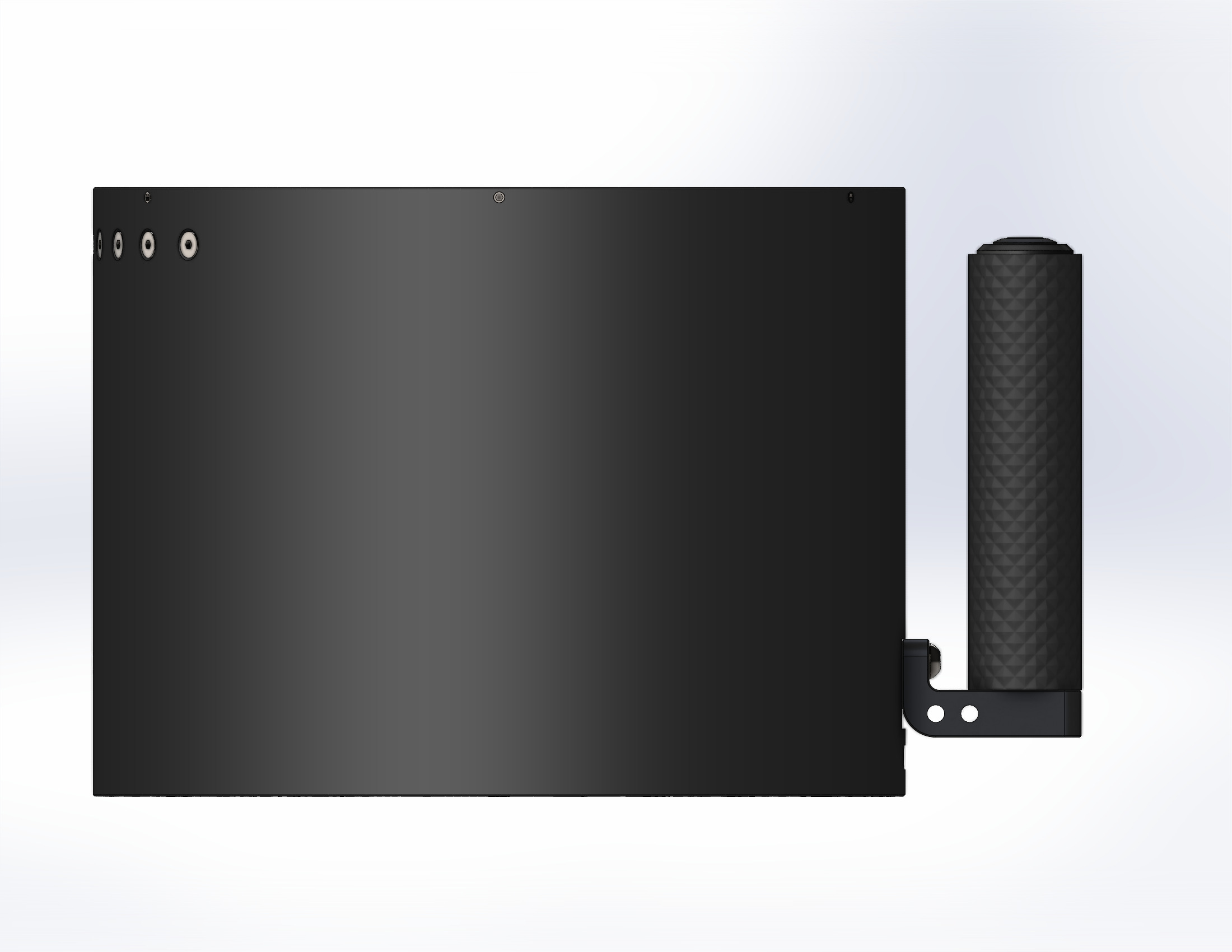
Other than some fasteners at the bottom face and around the front lens, the body is clean. It will be made from black anodized 6061 aluminum, fully CNCd.


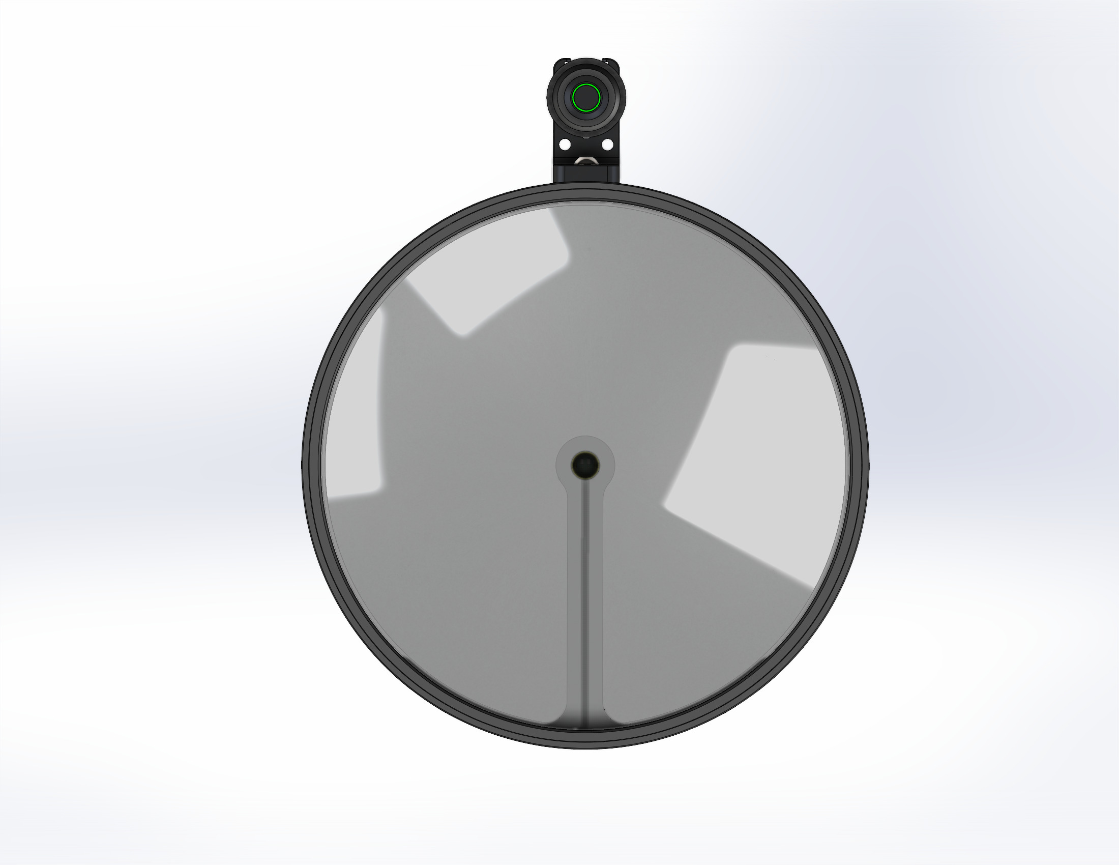
The front of the light I tried to optimize to be as much optic as possible. Body diameter was minimized, and the only obstruction is the single arm holding the laser phosphor emitter in the center.


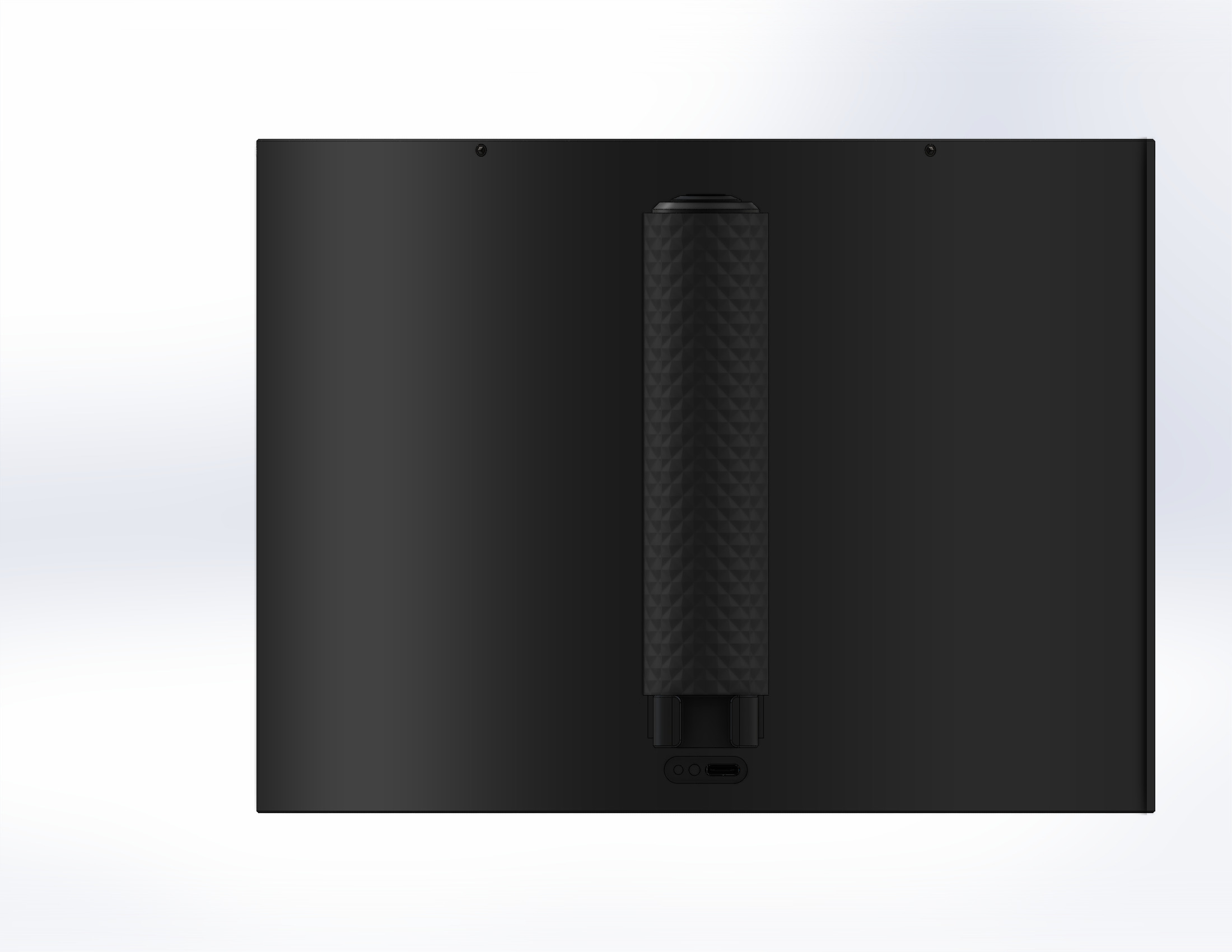
Underneath the light there is not much going on other than a 1/4"-20 tripod mount and 6 screws holding the back panel on.


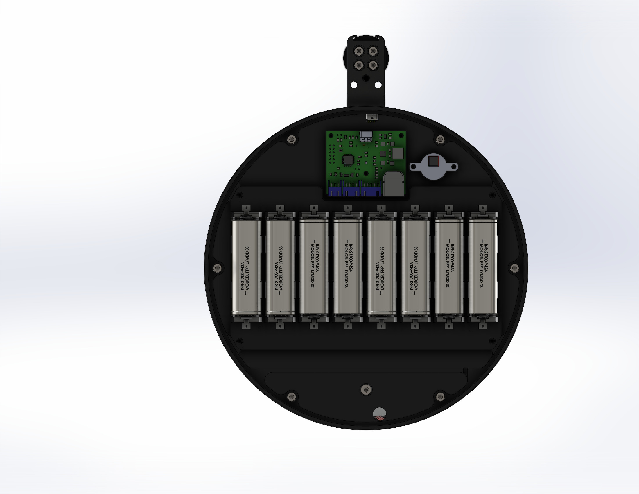
Inside you will find a custom PCB with 21700 cells, a USB C charging circuit, and a constant-current buck LED driver.
Here I have the cells arranged in 2p4s configuration, which theoretically allows for almost 10h of continuous runtime at max power.
I might decrease this to 4 cells just for the first revision, but we will see.
The goal is to have a single PCB that can do everything (battery holders + charger + driver) all in one in the future, but I am very new to PCB design so to start I will be using an off-the-shelf driver and charger.
The charger is the LiPow USB C fast charger which can do up to 60W fast charging, and the driver is a buck constant-current driver from MTN electronics.
I plan to use Amprius SA112 21700 cells as they have the highest capacity and I need very little current.


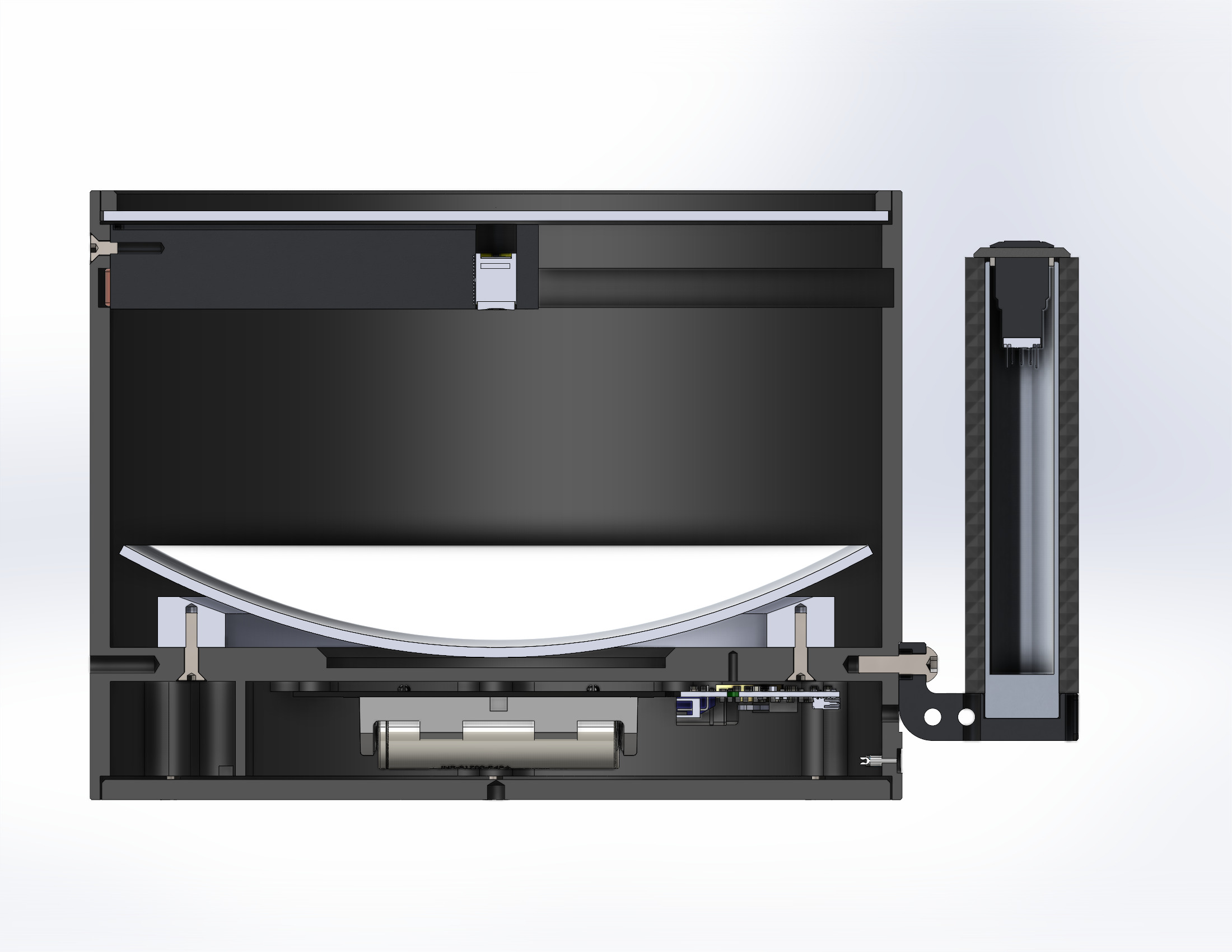
In the cross-section of the light you can see how the reflector is held in front of the laser phosphor diode.
It appears to be floating right now because to aid in vibration and impact dampening I will be using RTV silicone to hold the reflector to its mounting ring.
It is a very expensive and fragile glass reflector so hard impacts would shatter it without a shock absorbing mount.


Looking from a horizontal cross-sectional view we can see the aluminum arm holding the laser in place.
Two 200mm heat pipes are run through the arm to contact near the diode and provide heat transfer from the center to the outside of the searchlight body for cooling.
Because this laser only uses 15W, there is a very minor amount of heat being generated.
My hope is that the heat pipes are enough to keep it within adequate operating temperatures, but we will have to see during testing.


Overall it is a simple and clean design, which should be robust and water resistant while providing excellent range.


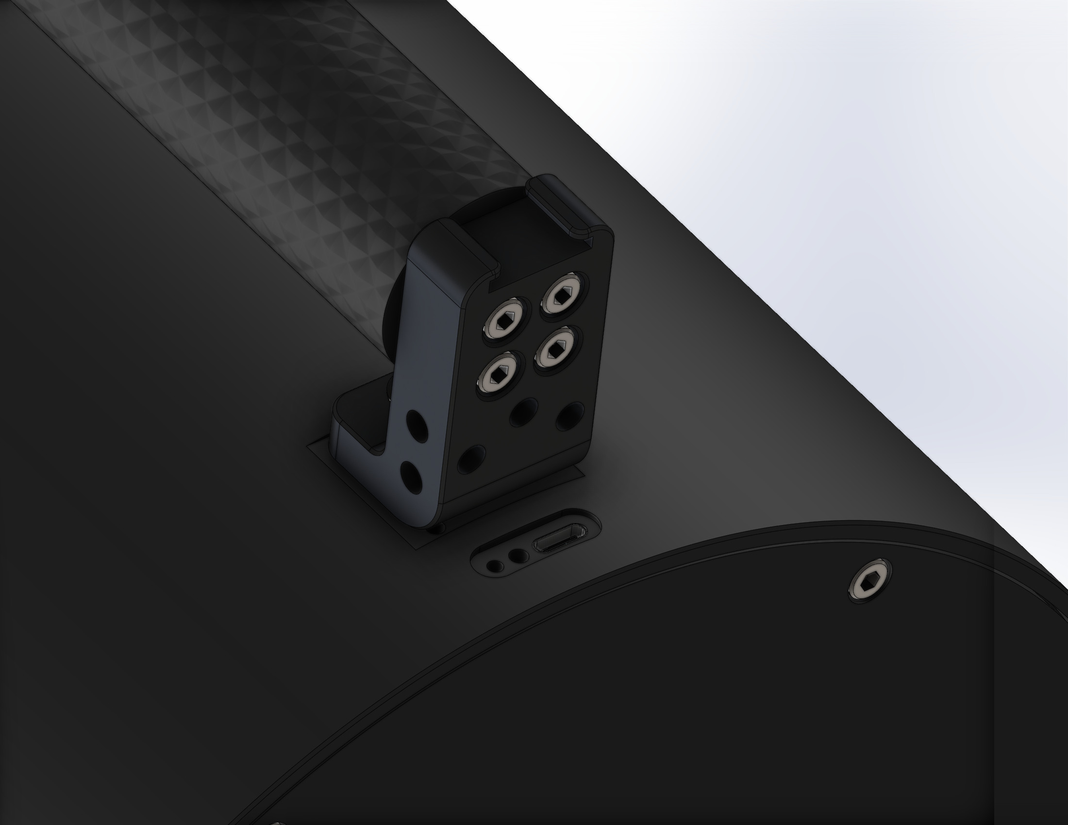
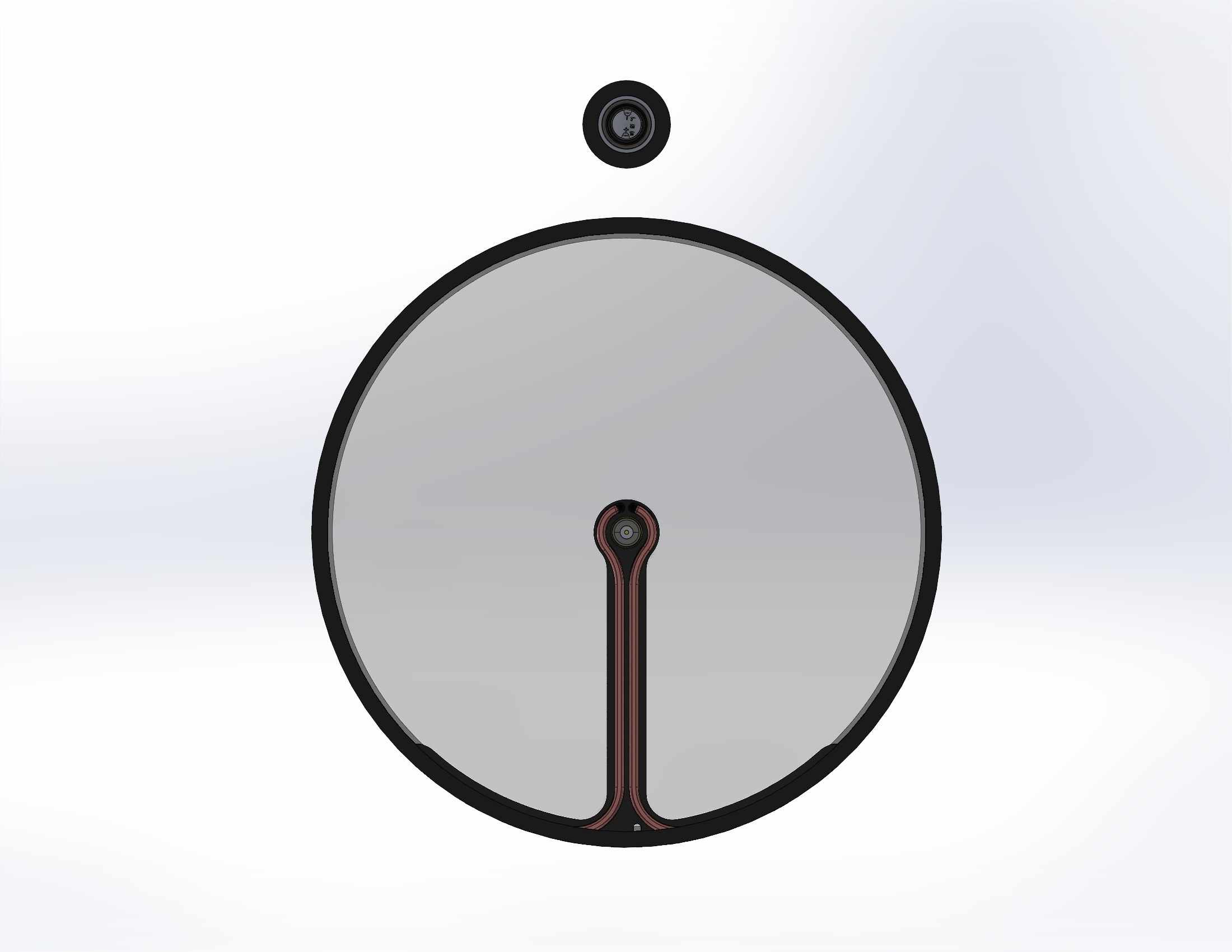
To aid with the water resistance the USB C port will be sealed on the back using silicone and a rubber cap will also cover it from the front to prevent dirt ingress.
The charger has an LED to indicate the battery charge state, and this will be routed to the second hole using a flexible light pipe.


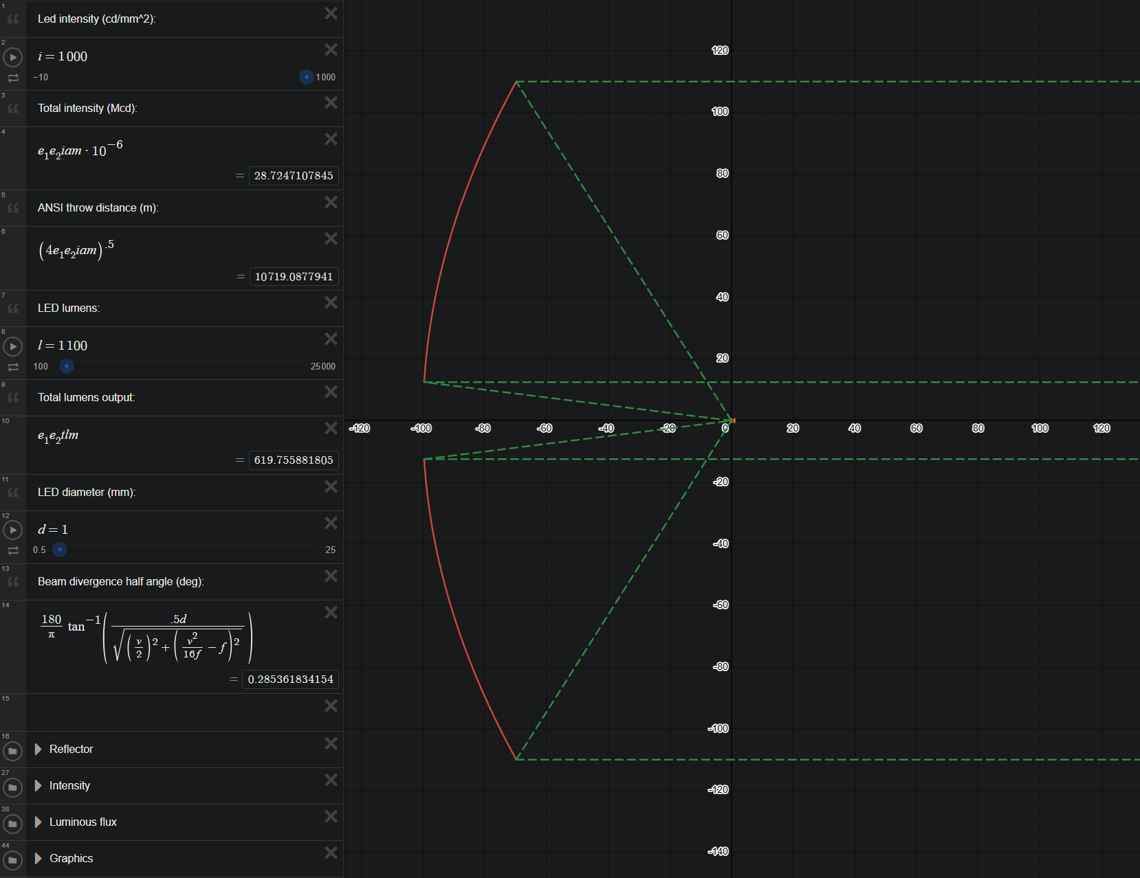
Using my recoil reflector calculator I am estimating approximately 600 lumens OTF and over 25Mcd, which will result in a 10km ANSI beam distance to 0.25 lux.
This is more than 2x the throw of my last build!

Stay tuned because in the next few months I will be putting this together and testing it :slight_smile:

Parts list:

  • Edmund Optics 220mm dia 100mm FL precision parabolic reflector (received)
  • Edmund Optics custom 232mm dia 3mm thick AR coated glass window (received)
  • Custom 1100lm 1000cd/mm2 laser-phosphor module from whitelaserlighting.com (received)
  • Custom 4s input MTN Electronics 3.5A buck driver (received)
  • LiPow USB C fast charger (received)
  • USB C port cap (received)
  • Vapcell F63 Amprius SA112 21700 cells (need to order)
  • Battery holder PCB (need to design and order)
  • Heat pipes (received)
  • Handle and pushbutton switch (received)
  • Aluminum parts for body (need to order)
  • Fasteners (need to order)

Latest updates:

15 Thanks

Nice project :+1:

That would be the Amprius SA122 at the moment, might be more durable than the Vapcell too, although that’s just speculation before knowing the results of Pajda cycle testing.

2 Thanks

Thanks!

Interesting, I was not aware of the SA112, but looking into it it seems like its nominal voltage is quite low, only 3.46V.
This results in a nominal energy of only 22.5Wh according to the datasheet, which is about the same as the 22.5Wh of the F63.
Since I am using a buck driver, power draw is constant, so a higher Wh is what matters in the end.

Another few cells I looked into is the M65A from Molicel (23.4Wh), and the FEB 68E (23.4Wh), both which are 3.6V 6500mAh.
Unfortunately I don’t have a way of purchasing these two yet, and the M65A samples aren’t available until later this year.

1 Thank

Pajda on his patreon tested the Amprius, vapcell and FEB and got :
0.2C 1C 2C
SA112 : 23.42 21.73 20.30
F63 : 21.61 20.17 19.26
21700G: 22.57 21.02 19.92

All three have nearly the same discharge curves except after ~3.1V where they start to diverge.

So the difference is small but the SA112 does have more energy than the F63 (or FEB).

2 Thanks

Interesting, might have to look into buying some then, thanks!

That’s strange that the cell with the lowest average voltage ended up with the highest capacity.

Regardless, seems like they are all really good, can’t go wrong with either one :slight_smile:

Well except the FEB, can’t find that one available for purchase anywhere…

It’s both that the F63 had lower tested capacity than rated (typical) at 6.131Ah at 0.2C and that the average voltage is lower than rated at 3.52V.

Also the SA112 tested higher than rated capacity at 6.772Ah and 3.46V average voltage, exactly as rated.

1 Thank

so excited to watch another enderman build. best of luck to you

how much do you estimate this to cost?

2 Thanks

Ah ok perfect, thanks for the data :slight_smile: I will be switching to the SA112 then.

Thanks! I’m excited too!

If we consider the raw parts cost for a single build it will be ~3.5k USD, but because of MOQs on some parts I will end up spending about 5k USD total.

Reflector - $1000
Lens - $500
Laser engine - $100
Charger - $200
Driver, PCB, batteries, etc - $200
Aluminum machined parts - $1000 - $1500

2 Thanks

Wowsers
Do you do any of the manufacturing in-house or is it all jlcpcb and similar services

Planning to use JLC or PCBWay, unfortunately I don’t have access to a 5 axis, the body is quite a complicated part and would be easiest to do on that.

Could be done on a very large lathe and 3 axis mill, but yeah I don’t have those tools in my house :frowning: haha

1 Thank

Can’t wait to see it in action!

2 Thanks

I’ve also recently returned after several years off the forum. I remember enjoying reading about your previous builds - I look forward to this one as well!

Seeing the LEP floating out on the long aluminum arm made me curious about how much of an impact thermal expansion from the heat generated by operation would affect performance. Given you’re using a small, high-intensity source, I think this would be a bigger deal than if you used a (larger, lower-intensity) LED, but I have no feel for whether distortion from heat will be enough to even notice.

Did you ever notice a difference in focus/intensity of your previous builds when they were cold vs. as they were heating up vs. after they were heat-soaked from operation?

I did some rough hand calculations for this new design, and depending on the actual temperature of the arm, the LEP might shift ~0.1 mm when the arm is 40°C above ambient and ~0.2 mm when 80°C above ambient. Since you have your recoil reflector calculator set up for your design, what do you see as the change in beam intensity if the LEP moves off-center by this much?

Assumptions for calculations:

  • Thermal expansion is primarily controlled by the Al arm and not heat pipes
  • CTE for Al: 23 µm/(m*°C)
  • 110 mm arm length
  • Arm has a consistent temp along length
  • Displacement of LEP is purely along the long axis of arm
  • Ignore thermal expansion of outer shell (I don’t know how valid this is - I wonder if expansion here might offset lengthening of the arm? It might also cause movement of the LEP in the axis perpendicular to the arm…)
4 Thanks

Thanks!

Good question, on my last build I had a 3-spider arm so the LED was always mounted in the center, but I can guarantee you that the manufacturing tolerances were much looser than 0.1mm.

Because the light emitting surface is about 1mm in diameter, even if the LED or laser was shifted by 0.1 or 0.2mm the focal point of the reflector would still fall on the light emitting area, giving you the same intensity and throw (assuming constant LED/laser intensity over that light emitting area)

What does happen if the LED or diode is not centered is that the beam will not be perfectly straight, so if the LED if offset 0.1mm and the focal length is 100mm, the center of your light source is 0.00057 degrees off axis. (equation is arctan(0.1/100))
This means that the resulting beam output from the searchlight will also be 0.00057 degrees off center.

As you can see it has very minimal effect and the beam would still look perfectly straight to our eyes.

It is only when you move the light source significantly far away from the centerline and there is no light emitting surface at the focus that you will start to see the reflected beam distorting shape and also going off to the side.
Thorlabs · Focus or Collimate Light with an Off-Axis Parabolic Mirror

So yeah, I am not really concerned about the expansion for this reason :slight_smile:
I think the laser will get damaged if it gets that hot too, so hopefully it doesn’t, but it’s only 15W so I’m pretty confident the two 90W heat pipes will be able to keep it cool.

3 Thanks

Thanks for the reply. Glad to see thermal expansion won’t be an issue for you.

I’m also curious about the LEP you’re using. The link you posted isn’t working - I’m guessing you bought from https://white-laser-lighting.com and the hyphens got left out of the URL? From your drawings, it looks like you’re using one of the threaded modules (like in the picture below). You mentioned you bought a custom item - what did you get customized and why?

1 Thank

Yes good catch, it is actually white-laser-lighting.com

I bought a modified version of the TNL1000S because that one only has a 70 degree full angle which works fine for lenses but would be bad for a recoil reflector that collects a much larger angle of light.

My modified version is called TNR1000S and has a 160 degree full angle light emission, so the full dish is lit up. The main difference is the phosphor being much closer to the front of the module and a very lower profile front cap that blocks minimal visibility from the sides.

I had to buy 10 of them because they were custom, so if anyone wants to buy some of my spares they cost $100 each, just send a DM

I chose this LEP because the 1000lm version of the Kyocera SLD diodes is discontinued and hard to find, and even if I got one the light projection is not clean at all, there are a lot of artifacts around the spot. LEP modules from eBay also don’t seem to go higher than about 500-700cd/mm2 so this one seemed significantly higher quality and better performance.

PS - I made an error in my previous post, I should have used arctan(), not tan(). The actual angle is 0.00057 degrees, significantly larger but still minuscule and likely unnoticeable :slight_smile:

Heat pipes are in the wrong place, hot side needs to be at lowest point, gravity is what creates proper flow inside the pipe. All you have to do is move the handle to the opposite side, where heat pipes are. swap up and bottom. TBH for 15w I do not think you even need them, solid aluminum “arm” attached to the body will dissipate 15w with no issues, indefinitely. If you had 150W then you’d need somethign faster than solid AL, but 15 is not much at all for the size of your light.
But it is very interesting project, looking forward to see it finished. I like the idea a lot.

1 Thank

Good points there! I have thought about all of those during the design though :slight_smile:

I previously did have the arm hanging from the top side where the handle is, but decided to change it for the following reasons:

  1. I wanted the large screws going through the body to be less visible, so moving them to the bottom is the easiest solution, next-best to drilling blind holes from the inside of the cylinder which would be very hard to do and require some special 90-degree machine tools.

  2. Heat pipes do perform best when they are vertical with the heat source on the bottom and condenser (cold) on top, however they are not required to be in this orientation. Some quick research showed that they still function quite well in other orientations even upside down as long as the distance isn’t very large. This is due to the sintered wick having very good capillary action and still working well against gravity. Because the distance is only ~100mm, it seems like the performance hit will not be that bad.

  3. The light will mostly be used as a sky beam and pointed towards the sky, so about 45 degrees or 90 degrees vertical. In these cases the heat pipes will be at an angle or fully horizontal so it will make even less of an impact to performance. The light is designed to sit on its bottom pointed up most of the time.

  4. As you pointed out, two 90W heatpipes are severely overkill for a 15W heat load. A solid aluminum arm would probably work fine. However, I always prefer to overdo the cooling on my builds rather than risk lower performance. For this reason I also think the inverted heat pipes will not be significant, as they will still be much better than solid aluminum, even with their reduced performance.

Thanks for the input :slight_smile: you do know your stuff haha

I assume LEP efficacy is, like LED, also affected by temperature, so it’s better to have it at a lower temperature with heatpipes even if would be ok at higher temp with just solid Alu for heat transfert

2 Thanks

Just judging by the size of the arm and surface area of the housing it could easy dissipate 30-40w imo, but it sure will not hurt if you have more heat dissipation.

Some years ago there was a designer who build high end light engines and high performance lights that cost more than SF, they had sapphire glass, gemstones for a button, customizeable UI was programed by simply holding them against computer monitor while running special app, name was LUX-RC, his high power light head was basically on a thin stem with few fins, he was very active on Russian flashlight forum, so we asked him why is the “leg” that held the head was so thin, would it not dissipate heat better if it was thicker, like basically any other light on the market, and it would seem logical, bigger chunk of aluminum could conduct more heat, but his thermal imaging tests showed it was not the case, heat traveled faster in thin leg than in a thicker one, pretty counter intuitive.

Here is the light I’m talking about.

2 Thanks