Likely because there is so much more surface area for heat dissipation..
1 Thank
I remember seeing that light a long time ago 
The reason a thicker leg doesn’t perform as well in that specific light is because a thicker (larger diameter) stem would eat away the surface area of the cooling fins, resulting in better thermal conductivity but overall worse temperatures.
The amount of cooling provided (measured in watts) is only proportional to surface area, so this makes sense.
Thermal conductivity (influenced by stem thickness, heat pipes, liquid cooling, etc) only changes the temperature gradient between the hot and cold side.
What this means is that because we cannot change the ambient temperature, that’s an inherent property of where we use the flashlight, thermal conductivity will dictate the delta-T and therefore maximum temperature of the heat source.
If the arm has 1000w/mk vs 100w/mk it would mean the LED/laser temperature might be 20C above ambient instead of 40C, but this is only assuming the cooling area is identical. At 20C ambient, this would result in 40C vs 60C. But in both cases it is the exact same heat going in and out, 15W for example.
This is analogous to a circuit with a resistor, the current in is the same as the current out, but there is a higher voltage gradient the higher the resistance is.
For that specific light you showed, where an increase in stem size would decrease the cooling fin area, then you’re changing two variables at once and I can definitely see why temps would go up with a thicker stem. For my light, because the cooling area is technically the outside of the flashlight body and not the stem (there are no cooling fins on the arm) a thicker arm would always improve cooling performance. Not by helping remove more watts, but by bringing the diode temperature closer to ambient temperature and reducing the delta-T. However, instead of doing a thicker arm which would only help maybe 50%, I used heat pipes which have tens or hundreds of times higher conductivity than solid metal, resulting in theoretically 1000%+ better conductivity performance and should get the diode even closer to ambient temp.
Yes, I am not exactly sure what diode is used in this engine but yeah lower temps typically mean better performance maybe I can even push a bit of extra current into it if the temps are good.
I would need to be careful to not burn the phosphor, however. That’s an issue that LEP engines can run into with too much laser power.
Hi Enderman
Like allways an intesting projekt.
Your SB. knocked my socks off -
At your new projekt based at my experience.
I have a strong hunch/apprehension.
The result will be good, I have no doupt about it.
The LUX results ,super.
That’s where my fear lies.
that yor SB will you more satisfy with the SBT 90.
For this time I am out to play with LEPs.
Your bigger diameter helps more to reach higher LUX results.
Just my two pence
But what do I know..
Good luck and I am watching you 
Regards Xandre
1 Thank
Hi Xandre,
Thanks! I always look forward to your creations as well!
I occasionally pop over to TLF to check out any updates from you haha
The goal for this one was not so much lumens but more just high-reliability stable performance and really long runtime.
This light could run for an entire 8h+ night non-stop, allowing for some sort of daytime solar charging and nighttime discharging.
More lumens will always require more battery power and cooling which ends up being more complex and expensive and also a larger/heavier light.
I do have plans in the future to do something more powerful and higher lumen output but for now this is all I can afford haha
Not to spoil the surprise, but I will likely go back to lenses after this and use some pre-made LEP engine as those are becoming more common.
There are some with 10k+ lumens and >2000cd/mm^2 that are designed to work with lenses, but unfortunately due to their narrow emission cone I could not use those for a recoil reflector.
This is about the best I could find that had close to lambertian emission.
Cheers!
2 Thanks
Some pics of the lens and reflector I just received 
Lens is left covered until assembly to avoid scratches and dirt.
The lens is custom cut (by the manufacturer) from 3mm thick AR coated float glass window from Edmund Optics.
Reflectivity is almost 0%, and transmission is close to 98%.


The reflector is a 220mm diameter parabolic aluminum-coated reflector, also made of glass and from Edmund Optics.
Hopefully the additional rigidity and precision of the glass compared to my last build’s electroformed reflectors provides an even more focused and sharp hotspot.
It should be a tighter beam regardless, due to the longer FL and smaller light source I am using in this build.
The goal is a sharp pencil beam with low divergence!


The edge of the reflector has a flat all the way around so instead of gluing a mount to the back I am going to change the design a bit so that I clamp down around the reflector to hold it in place.
Currently finalizing the CAD design so I can order the metal parts for the body of the light in the next few weeks.
Cheers everyone!
12 Thanks
New update! - Custom PCB!
I have spent some time the past couple of weeks learning KiCad and have finally designed my first official PCB
It is very basic because I wanted it to arrive quickly and without issues as I want to have this light built and working within the next month.
Therefore, all it contains is four battery holders for the 21700 cells and some solder pads for wires.
I do plan to add more functionality over time, so this is most definitely not the final design.
And yes, I did accidentally place the output pads on the opposite side of where my driver is 
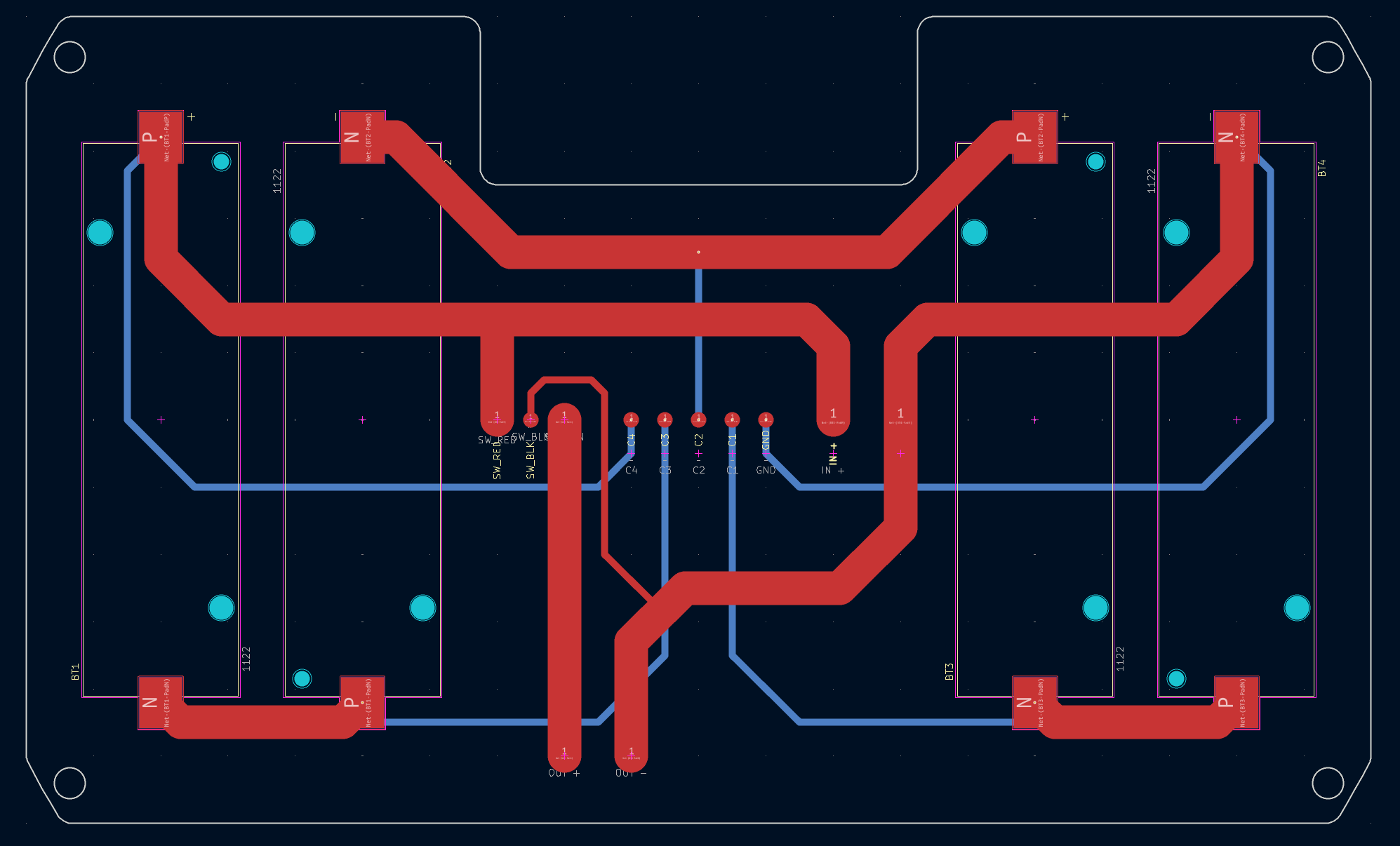
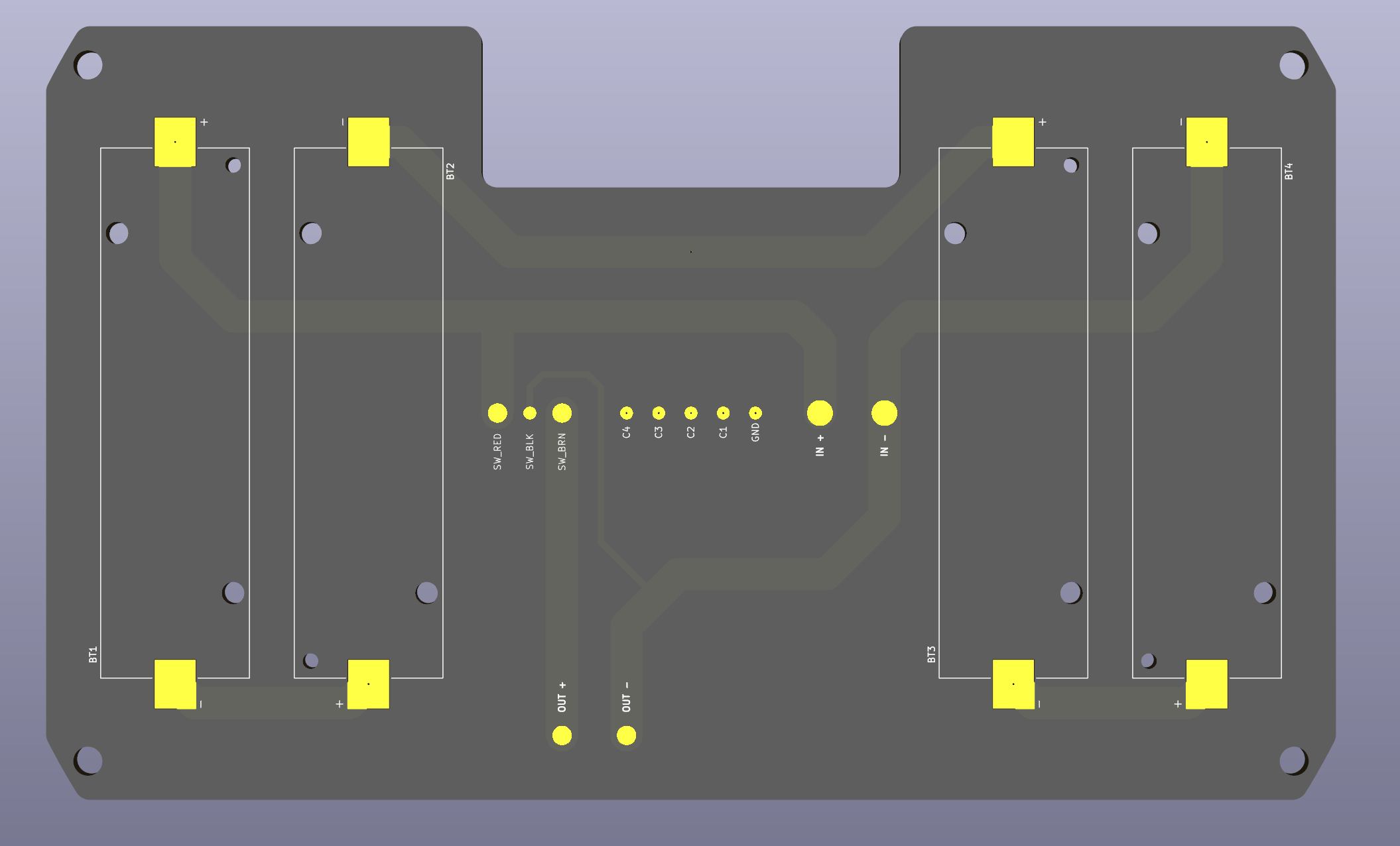
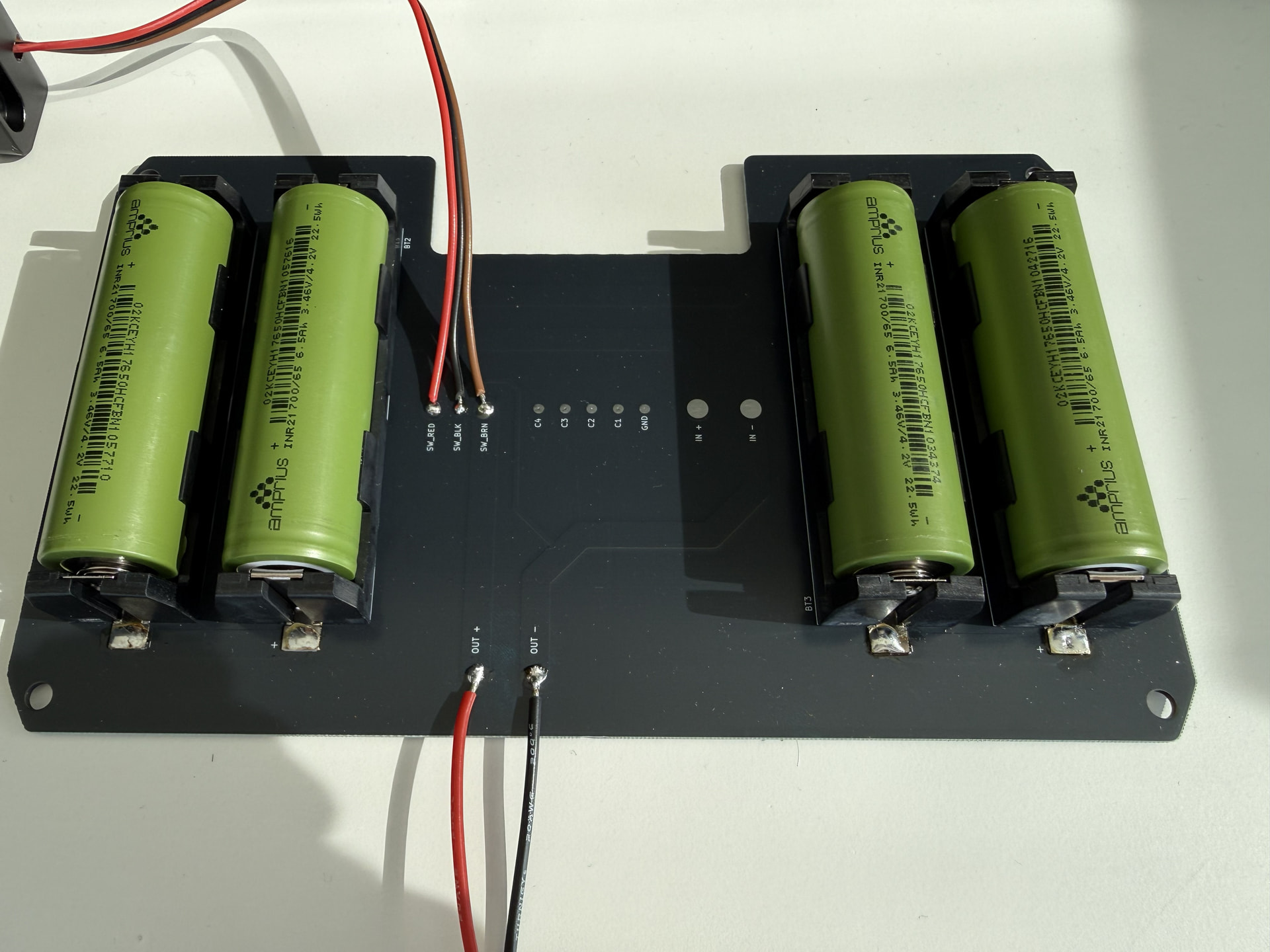
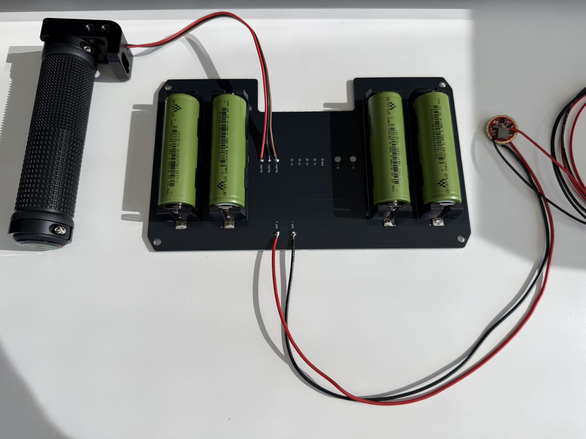
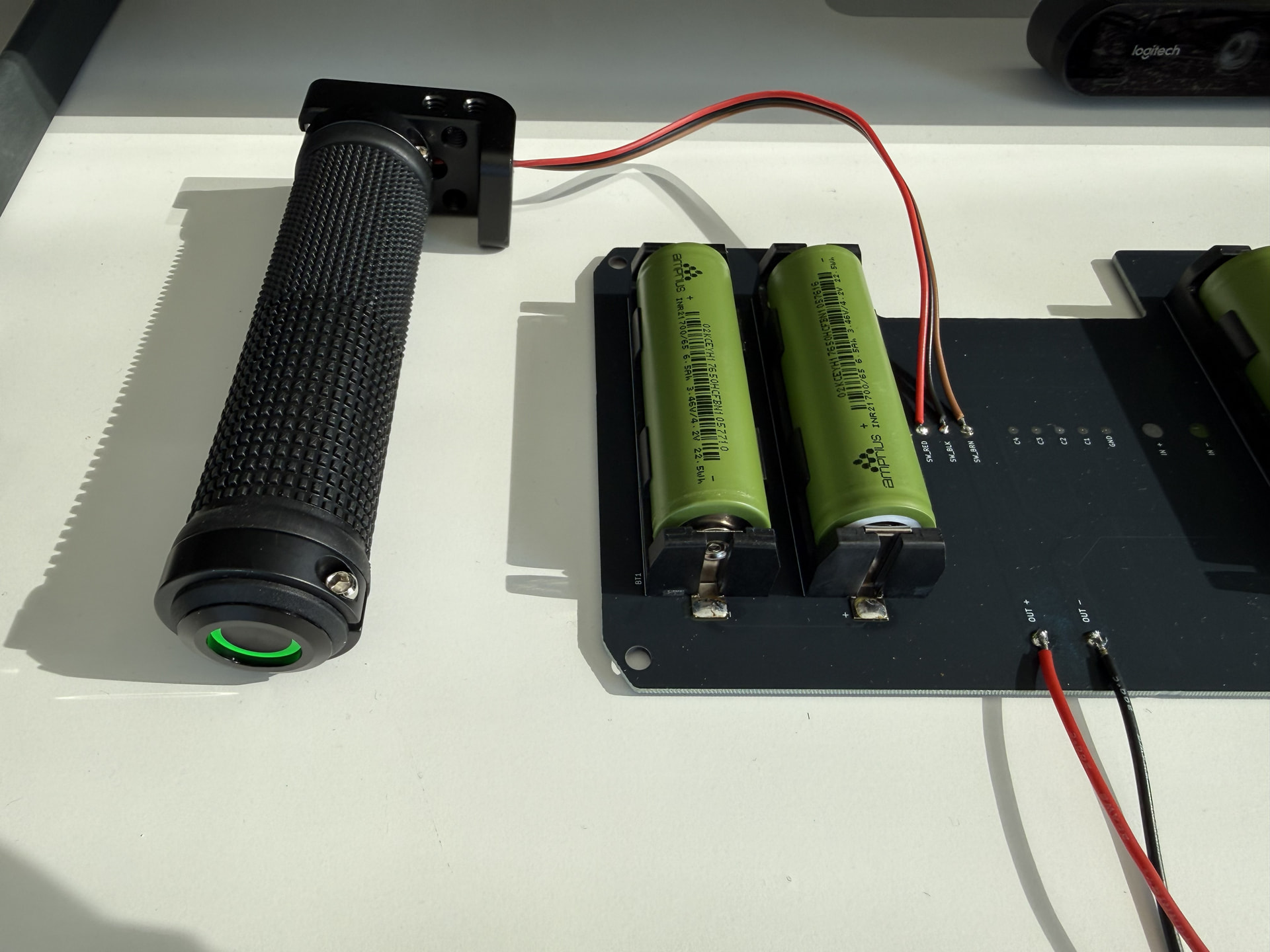
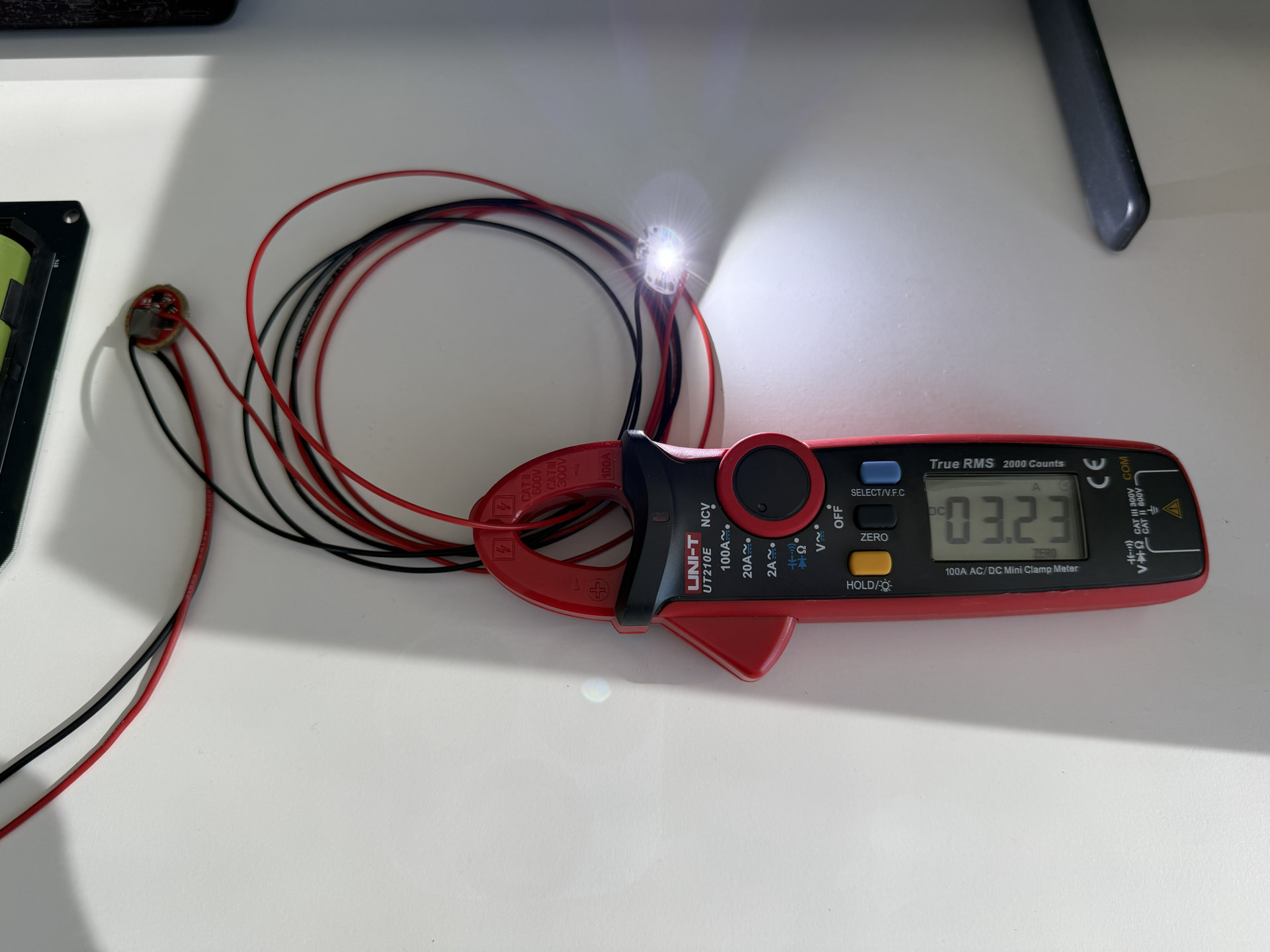
(testing with an LED here, not the LEP diode)
Current features:
- 4x 2170 battery holders in 4s1p configuration
- Charger input pads
- Charger balancing pads
- LED switch pads
- Driver output pads
Future additions:
- Connectors to replace solder pads
- Cell balancing fuses
- Main output fuse
- Voltage/charging status indicator LED
- Buck driver (to replace the external driver I am using)
- USB C charging circuit (to replace the external charger I am using)
- Zero-drain shutdown or ultra-low quiescent current
3 Thanks
Following with keen interest—I’m super curious to see how well the large reflector plays with the tiny LEP source.
Going off the listed spec of 1100lm @ 1000cd/mm^2, assuming a uniform, Lambertian emitting source, it would have area (1100/pi)cd/(1000cd/mm^2) = 0.350mm^2, and diameter 0.668mm. Pretty small, but still within the same order of magnitude as the black flat from your previous build, maybe reasonably tolerant of thermal expansion. I wonder how well the uniformity assumption holds up for LEPs.
If the above assumptions hold up then in theory pi(110)^2*1000 = 38Mcd is possible; I don’t think that reflector/lens losses + blocking from the LEP mount is enough to bring that down to 25Mcd. What am I missing?
Going off your Desmos diagram, the edge of the reflector is 70mm away from the emitter’s plane and 110mm off to the side, with distance from emitter being 130mm. This means that the divergence angle of the central hotspot is roughly 0.668*cos(arctan(110/70))/130 = 0.00276 radians, or 0.158 degrees, almost within the range of some lasers and over 3 times narrower than the angular size of the moon and very demanding of reflector precision. Quite a cool light to behold, and equally difficult to aim!
1 Thank
Thanks for the interest!
Yeah it is a pretty small hotspot, but this time it is round and should give an even nicer beam shape than any lens thrower with a square led
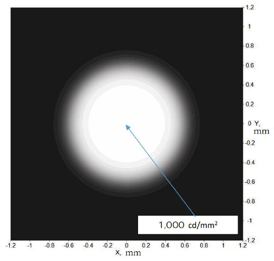
From the LEP datasheet^
Significantly better than the Kyocera SLD chips which have horrible reflections.
Several things actually bring down the final performance, see below:
- reflector reflectivity is 85%
- Front window transmission is 98%
- Reflector actually has only 210mm usable diameter due to an outer lip
- Area losses due to the 25mm diameter center holder and 20mm width arm
- LEP module true intensity, driver current variances, and temperature influence TBD
I think if you do the math it should match up with my calculator Laser Recoil | Desmos
If I reach 25Mcd I will be very happy, otherwise I will probably try pushing some more current or improving the cooling.
I also sent some single crystal phosphors to whitelaserlighting so they can do some testing and see if they can extract more performance or push higher laser power.
Unfortunately I don’t really have the time or setup to test that myself at the moment, but theoretically it is the best way to get maximum LEP performance.
Latest status of machining:
-All parts complete except the main body tube, which is by far the most complex part (and cost $900 USD  )

1 Thank
Looks like there’s considerable gradient in brightness across the LES, as the true diameter seems closer to 1.5mm than the 0.67mm derived from uniformity assumption. This means the region of maximum luminance (1000lm/mm^2) is smaller than predicted, which demands even higher optical precision.
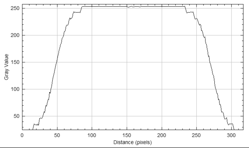
I wish they had a proper diametrical profile plot–there’s not much information about beam shape to be extracted from this diagram, aside from the circular shape and the central intensity label of 1000 cd/mm^2.
Here’s ImageJ’s attempt at a profile plot. The suspiciously well-behaved curve (stepped, with odd symmetry about the inflection points) suggests that the image is an extremely crude illustration–not even a simulation–that offers little information about intensity distribution.
Thanks for explaining! I’ve underestimated losses at the reflector and didn’t account for the reduction in effective diameter. 25Mcd is starting to sound an optimistic estimate.
My greatest fear is the reflector not having enough precision to focus the region of maximum luminance, or the mounting being insufficiently rigid to keep the reflector/LEP from moving relative to each other. But I’ve never worked with such high-precision builds before and don’t know what to expect, so I expect to be pleasantly surprised.
This sounds really interesting! I’ve never heard of single-crystal phosphors but the concept does make a lot of sense–powdered phosphors are lossy at grain boundaries, the combined area of which a single crystal minimizes. The Nichia 519A has a much rougher phosphor than the 219B, presumably with this in mind.
I am very curious: are you sponsored by an institution for these projects, or are you paying everything out of your own pocket? I’m also curious what you do as a profession, but recognize that it is too intrusive to ask in public.
1 Thank
Yeah that intensity diagram does seem a bit unrealistic haha but I guess we will find out soon!
My previous experience with a recoil reflector was that it was actually not that hard to focus when aiming for “focus at infinity” or perfectly collimated using my paper and hole method.
You can see this effect pictured here in my focusing guide: Light collimation with an LED flashlight
As the distance grows so does the projection of the light emitting surface (LES) so if you’re off by a fraction of a degree from perfectly parallel you still end up measuring the same intensity with a luxmeter, because everything is overlapping at far enough distance.
Obviously this is much easier with a lens since you have a nice front-facing LED even at the edge of the optic, while a recoil reflector would only capture a sliver of the LED at higher incident angles.
This reflector I picked for this build doesn’t capture as wide of an angle as my last build, and the focal length is longer, so both of those factors will make focusing easier.
Actually the main issue I had with the previous reflector was that tubing and wires would touch the side of it and push on the edge, which caused the parabola to deform and not focus properly on the LED. Electroformed reflectors are pretty bendy.
I am hoping that the glass construction of this new reflector completely solves that, it should be as rigid as a lens.
The main benefit of single crystal phosphors is that they have excellent thermal properties, being a single crystal, so you can pump lots of laser light into them without burning it up.
Powdered phosphors also require some silicone or other medium to hold the powder together, which also makes them more likely to burn under high laser power.
Ceramic phosphors are better but not as good as a single crystal from the research papers I have read.
The down side of a single crystal phosphor is the cost, which can be hundreds of dollars for something just a few mm in size.
If you couldn’t tell already I am an engineer haha
I make enough money to spend on my hobbies from time to time but I hope to commercialize some of my ideas in the future as well.
2 Thanks
This is a very illuminating idea in an exceptionally clear writeup! Great way to see how to make the beam approximately parallel.
I tried it on a forward reflector out of curiosity, and it works a bit less well–for a circular LES, the projection varies a lot in both shape and size depending on where the hole is, from ellipses to lunes. Recoil reflectors shouldn’t have this problem as there is a coherent, roughly circular virtual image.
The writeup also makes it clear why a reflector is a must for this project: the chromatic aberration produced by the lens may subtend an angle wider than the hotspot, effectively diffusing it.
That’s a great solution! Reflectors deforming under mechanical force is not something I encounter often with common lights, though as things scale up in size they do become less rigid. I hope the glass reflector works out!
Ahh I see, thank you for explaining! Is ceramic phosphor the stuff Osram uses in the CSLNM1.TG and related emitters?
1 Thank
Yeah the chromatic aberration is pretty bad and although special multi-stage achromatic lenses exist I’m sure it would make the already extremely high price of an aspheric lens even more astronomical 
However, a longer focal length lens bends the light less, and therefore the effect can be lessened.
Larger emitting surface also makes the separation less obvious.
Still, reflector with zero chromatic aberration can’t be beat
I am actually not sure what they use there but I would guess it is.
Looks very different than the “painted on liquid” that the Cree emitters seem to have.
2 Thanks
So true! Decent single-component aspheric lenses are already very expensive, a multi-stage achromatic must be truly astronomical.
Very true about the longer focal length! The only downside is that it makes a light unnecessarily long. I wish catadioptric optics can be had in the 200mm diameter range–it produces a design that is much more compact than regular TIRs and convex lenses, while avoiding the heatsinking and occlusion problems with recoil reflectors.
Make perfect sense–it boosts the signal (projected image) to noise (aberration) ratio.
Incidentally, recently I’ve been noticing this phenomenon a lot playing with Fresnel lens throwers. Compared to a bare emitter behind the Fresnel, I actually get more candela after slapping a collector in between, consisting of an achromatic doublet followed by a regular convex lens, which should incur at least 7% reflection loss. This collector magnifies the virtual image (and thus projected image) by a linear factor of 2, which made the quite bad chromatic aberration barely noticeable.
Before buying the Fresnel I built a recoil prototype using a $1 “solar burner” parabolic mirror about 10cm diameter and roughly the same aspect ratio as your reflector, which resulted in severely misdirected reflections near the boundary, achieving only half of the candela of a quality optic with comparable size. After spending hours reading reviews to assess the quality of cheap recoil reflectors (mirascopes), I decided that I should just get Fresnel and live with chromatic aberration in exchange for much more diameter per $.
It seems to me that Cree, Luminus, and Osram all have their style of phosphor consistency. Cree is usually suspended in silicone, Luminus domeless emitters are truly domeless and appear to be some some of powder compactified into a disc–the surface is still visibly rough and a magnified image shows randomly-colored patches.
Osram is the strangest of them all–the phosphor surface is hard, shiny smooth, and completely uniform in color, which made me guess ceramic.
1 Thank
Yeah, its always a trade off between either a tight beam or compactness.
Impossible to have both because you can’t shrink a light source, only move your optics further away.
Mentioning catadioptrics reminded me of the Carclo ones I have, and I started thinking about whether it is possible to make something similar using reflectors only, similar to a telescope with primary and secondary mirrors.
That would allow placing the light source behind the primary reflector, shining onto a small center reflector before bouncing into the main parabola.
I am not sure if a spherical convex mirror would suffice, it might have to be hyperbolic or some other more complex shape to get the focus right.
Also the benefit of easier cooling/mounting is offset by the losses in the secondary mirror, so a multi-stage design might not be worth the effort.

I also searched for a long time and considered various mirascopes, makeup mirrors, etc. but never found something of sufficient quality for a good beam.
That’s why I had to go with electroformed for my last project.
As the focal length is longer, it becomes easier to focus light, as you found with fresnel lenses.
They can be plastic or pretty cheaply manufactured and still work well.
However a mirascope mirror has a few cm focal length is very close to the light source and any imperfections will result in huge aberrations.
This is also why large NA lenses are so hard to make and expensive.
Yup, and according to my estimates they have made another big leap forward in intensity performance with the new Black Flat X, which nobody has tested yet.
Might need to buy one and test it myself
1 Thank
I was thinking about trying something like this too! I gave up on it because I couldn’t think of a way to cheaply source the convex secondary mirror with the appropriate shape.
In the diagram you shared, if we assume the “focal point” (call it P) is the emitter (or its virtual image through a convergent lens), and that the primary mirror is parabolic with focus Q, then I believe the secondary mirror should be hyperbolic with focus Q and conjugate focus P (with the remaining degree of freedom, curvature or aspect ratio, adjusted according to the dimensions of the parabolic primary). This way a ray emitted from P reflects off the secondary mirror with a virtual image at Q.
You’re quite right that the increased losses might not make it worth the effort, since you measured a rather high 15% loss from your very high quality parabolic mirror for this project. The intensity just can’t afford to take another 15% hit.
A somewhat unrelated question for you–when people make plano-aspheric lenses used for focusing thrower LEDs like a zoomie, what’s the curve on the aspheric side? Is it parabolic or hyperbolic or some harder-to-describe shape? I haven’t been able to find a consistent answer. My eye could not distinguish the curve from a paraboloid.
That makes sense. I also had a look at some acrylic concave mirrors on aliexpress sold as decorations or fire starters, but became unconvinced after seeing the reflections in the product image and noticing how badly warped straight lines became.
I’ve got some Fresnel lenses with focal length roughly equal to diameter, and with a sufficiently large emitter (say with diameter at least 1/50 that of the lens), the intensity per area seems to slightly exceed that of forward reflectors. This is all in spite of deformations in the lens, which are easily visible as unevenness in the beam at close range, before it converges to the projected image. I’ve been able to “cheat” compactness despite the long focal length by making the structural body collapsible when not in use.
I had a quick look at the datasheet–for some reason the rated max pulse current is lower than that of the White Flat (1.5A against 3.3A). Also, the die seems a bit bigger–the dimensional drawings show 0.96mm edge for white flat and 1.15mm edge for HHL631, so the LES is (1.15/.96)^2-1=43.5% larger, which would offset a 1.4x higher brightness. What am I missing?
1 Thank
The 85% was for this specific aluminum coated reflector, some places offer enhanced aluminum with 90-95% reflectivity, or if you can do with less environmental resistance silver can get you 98%+
The best is a cold mirror coating which typically has 99%+ but those are not cheap.
It’s neither, its a custom equation, which is why they are so difficult and expensive to make:

Yeah, fresnel lenses are the only affordable way to get large diameter lenses at the expense of some imperfection and losses.
For my next project I would like to use a 200mm non-fresnel aspheric lens but that will cost $5500 
Oh good point I did not notice that, you might be right…
1 Thank
Ah I see! I had no idea that the reflective coating gets this good if one is willing to shell out money. I’m surprised that they decided to pair your reflector’s amazingly precise geometry with an inferior coating.
Thanks! Do you have an expository article or some sort of writeup behind this expression? I’m trying to make sense of it and running into some difficulties. From what I gather:
- R is the radius of the lens, r in [-R, R] identifies a point/ring along the base of the lens, and z(r) gives the height of the lens at radius r
- kappa, a_4, a_6,… are secondary parameters for determining the exact shape, and only even powers are present to ensure symmetry and smoothness
- For simplicity I can just scale to let R=1, and the main term simplifies to the equation of an inverted ellipse (here kappa = 0.5)
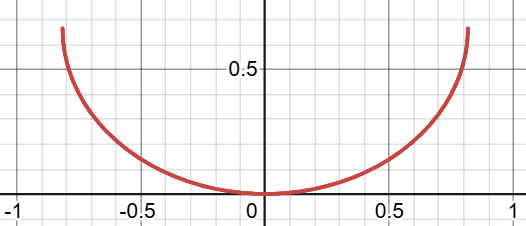
I’m having trouble with this because
- The shape is not supported on the full radius |r|<=1,
- It looks upside down, and
- The curvature increases near the boundary, which is opposite of what I observe in aspheric lenses.
Any insights/clarifications would be much appreciated!
I wouldn’t be surprised if they do come up with the next throw king. Among throwy emitters, the Osrams are the only ones I’ve seen that use both a flip-chip design and a (presumably) ceramic phosphor, which might explain why they still remain the reigning king of surface intensity (>1000lm/mm^2) after 9 years. It is long overdue for an update.
Yeah I guess it’s just what they had as a stock option, it would have probably cost a lot more to get it with one of the other coating types
Yeah that is from Edmund optics where they explain it pretty well: All About Aspheric Lenses | Edmund Optics
That isn’t the radius of the lens, that is the sag of the lens, or how much it deviates from a parallel plane
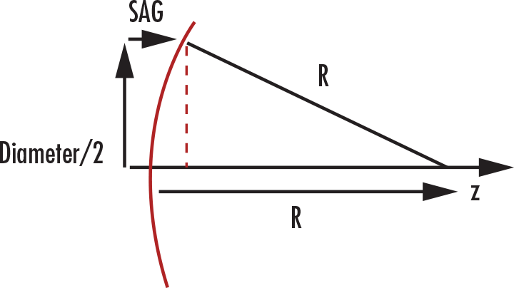
Its done this way because its basically a variable radius surface but when machining/polishing the physical part the machines work with x/y/z coordinates rather than radial polar coordinates from the focal point.
The machine has no idea where the focal point is, just how far from the center axis you are which is the ‘s’ term in the equation (note that it is not the r from the focal point like pictured above)
The Edmund Optics page actually shows the equation with s instead of r to avoid this confusion, unlike the equation in the first image I posted which has r in it.
Yup! LEDs are still much cheaper and easier to use than LEPs so new high intensity options are always nice
1 Thank
Wow thank you for this resource! Having a read.
EDIT: my previous guess was indeed off at a few places–most importantly, the kappa parameter is negative and determines the type of the conic, with the ellipse/hyperbola boundary at -1. Thus it can be thought of as the negative of eccentricity. And R is not radius but a curvature parameter.
It would be very nice if there existed some ray-tracing demonstration to show what effect the various parameters have on the lens…
Very true! You had multiple builds in the past using the Wavien collar, which roughly doubled the surface luminance from what I’ve read, and I don’t think any bare LED can achieve that any time soon. Shame that such a simple (I might even say obvious) idea can be patented and that nobody is doing anything with it. (Im)patiently waiting for the patent to expire in 2031…
1 Thank