You’re right DBCstm, that’s certainly one major difference! I encourage everyone to build their own. :-p The only drivers I currently offer to build are the drivers in my Lux-Pro kit.
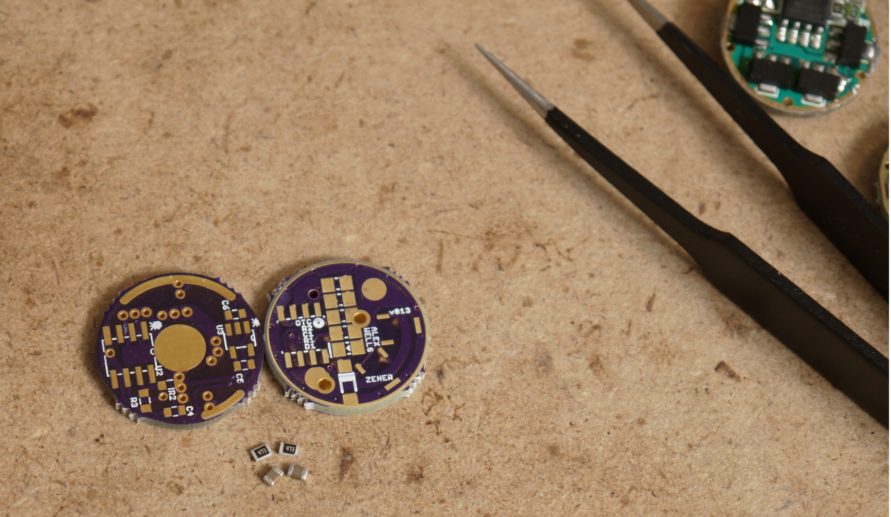
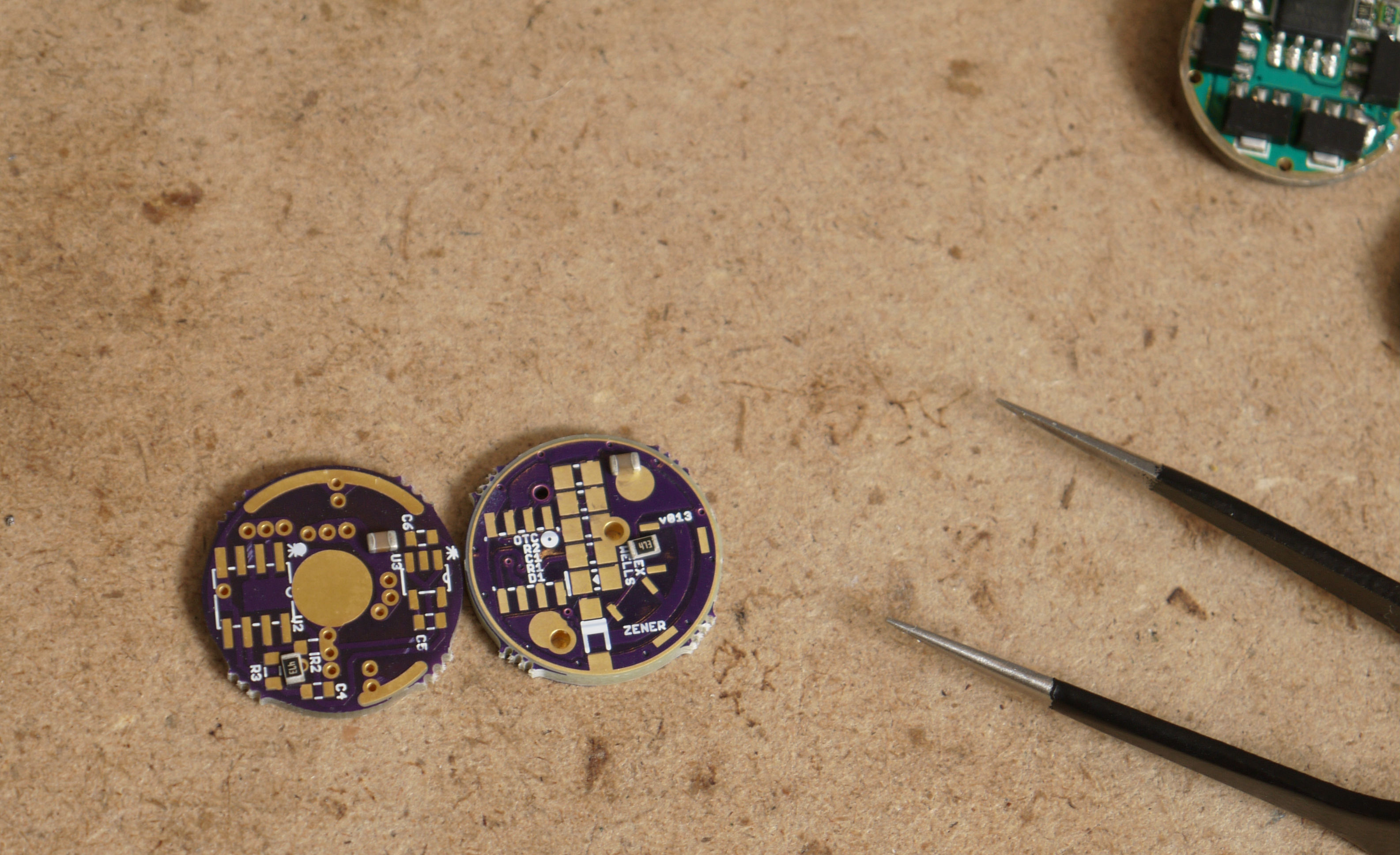
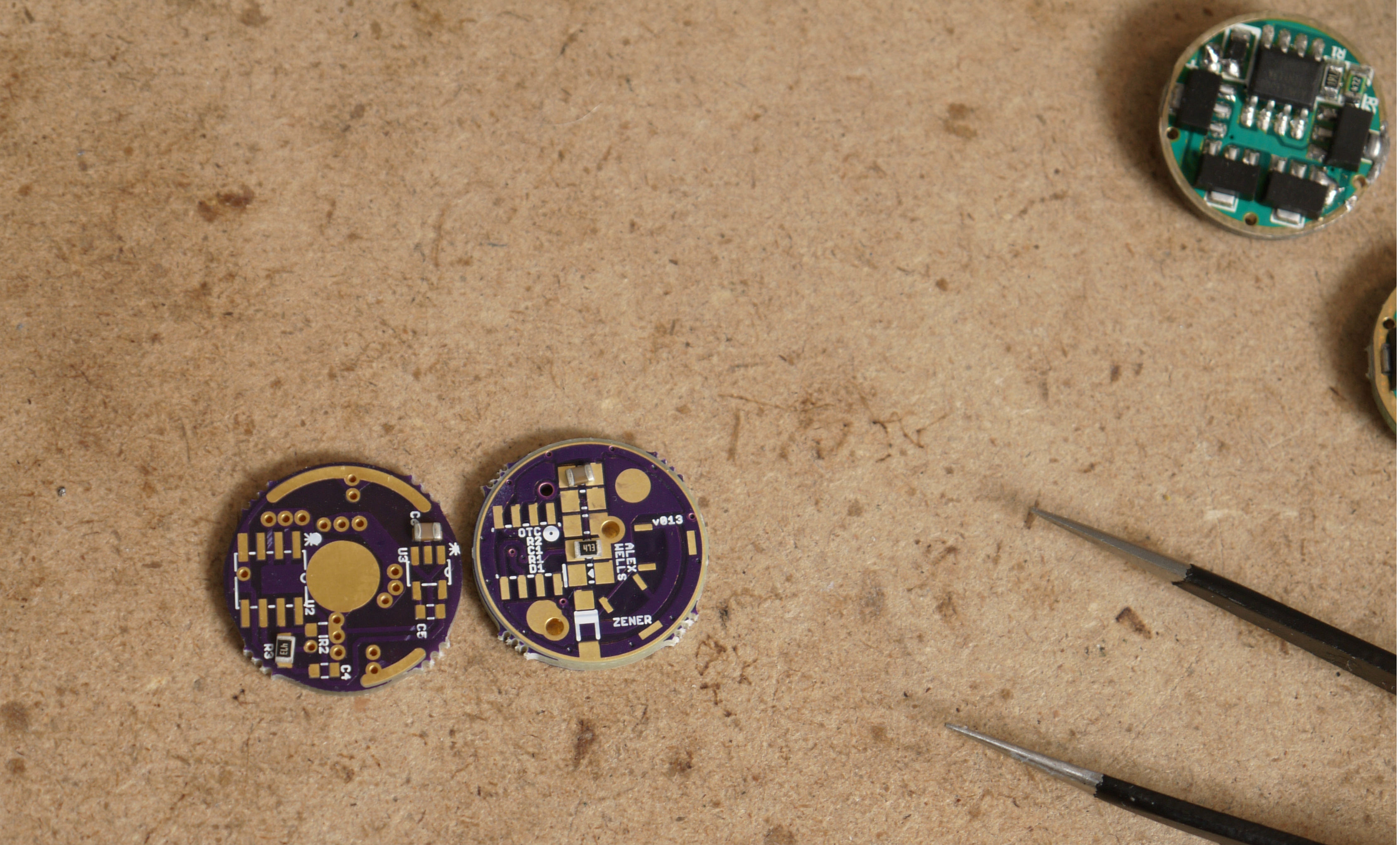
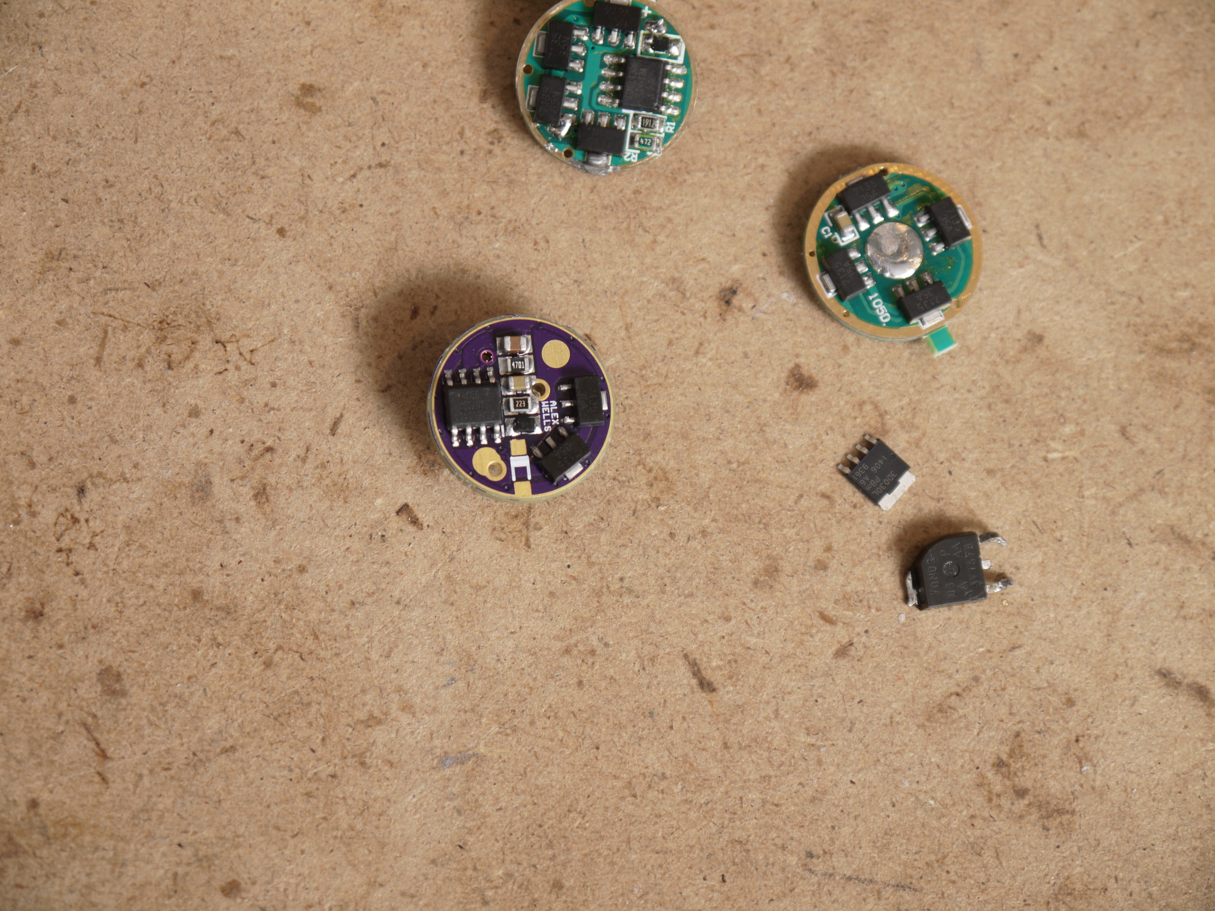
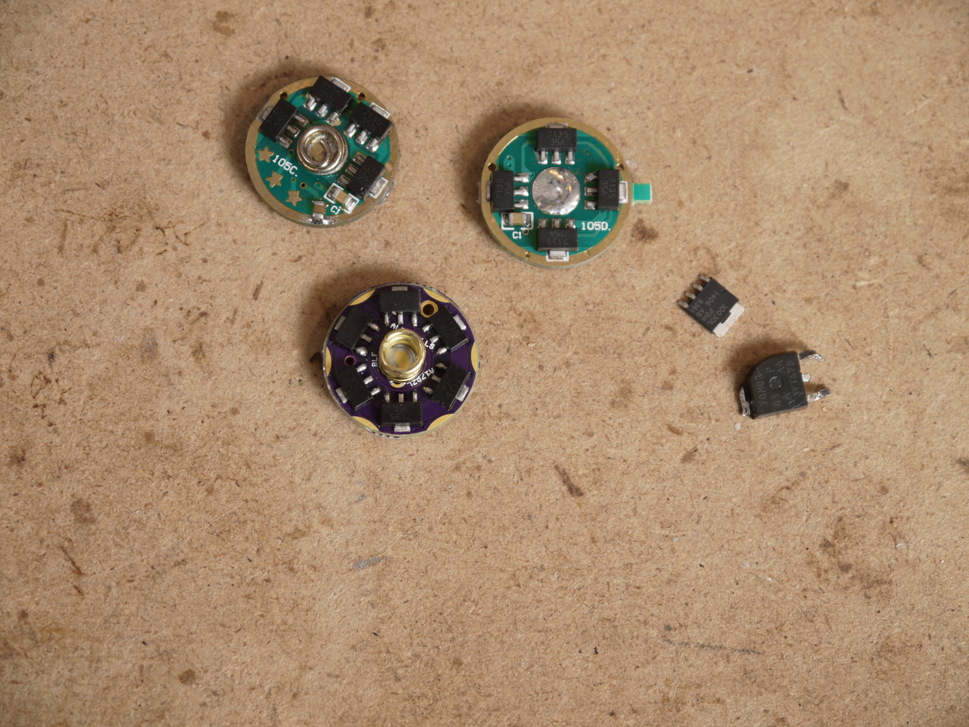
To underscore that point: These 3 pictures show my A17PZL driver (which uses full size 0805 footprints) on the right and a different driver which employs 0603 footprints on the left. As you can see I’ve got a pair of 0805 sized components for each driver and I proceed to lay them onto the pads. 0603 pads are usable for 0805 (and there is a specification for using that sized pads for 0805, it’s not just some hack). The difference is that hand soldering, inspection, and rework are all more difficult with the smaller pads. Click for big versions.
I like that PZL driver, works great and looks really cool installed.
I do believe that’s the first time I’ve ever put 7135’s on a board that didn’t have 7135’s under em! lol (to make myself feel at home, I did that as well. )
I felt like I was leaving something out and sure enough I was. I forgot to mention that these were actually pics of the second A17PZL I’ve seen assembled. DBCstm got started a bit earlier than I did!
These look so awesome. I got my boards from Oshpark about a week ago… hoping to assemble a few in the next couple of days. Can’t wait to try them out… and also to get my feet wet on messing with firmware.
One question… any issue with using 1912 resistors (like from a standard 105C or qlite)? Noticed you used some with slightly higher value above. I’m far from an EE so I have very little understanding of what the resistors even do for the MCU. Is the difference something I need to account for with the voltage monitoring parameters in the firmware?
Thanks grantman321. The 19.1k resistor can work fine with tweaked parameters, it’s not a problem. 22k is cheap and easy (it functions at least passably with the stock values). Take a look at the comment section at the top of STAR_off_time.c to see a description of how those resistors are used and a summary of the math. Understand that we’ve moved the input for the voltage divider from the back of the diode to BAT+, so the “~.25 v drop from the protection diode” which JonnyC mentions is now gone. I just use a voltage divider calculator (this one).
I go on a bit more on the subject over here, and probably some other places too: Oshpark Projects (#917)
As I see it, you’re already running dual PWM by utilizing the single chip for moon. To select a second mode to also use that chip would maybe take a 3rd PWM channel? And available pins on the MCU are scarce? Or is it for a totally different reason?
Totally different reason. It’s all just software limitations. JonnyC’s method of controlling the two PWM signals together is fairly straightforward, easy to implement, and easy to understand.
The method used in STAR_off_time and STAR_on_time is simply to draw a line in the sand, say for example at 40/255.
Firmware mode level:
Primary PWM out:
Alt PWM out:
255
255
255
200
200
200
100
100
100
45
45
45
35
0
35
9
0
9
We only maintain one “PWM/mode level” variable (0-255), but we have two outputs. Various features like stepdown & rampdown manipulate that variable directly. Workarounds can be implemented to get 255/255 out of our ALT PWM output and 0/255 out of our primary PWM output at the same time, but they’d potentially behave badly during stepdown and things. A full rewrite is a lot of work and doesn’t seem to get us a lot.
Positive is the pad close to the LVP components on the other side or you can use the via that touches R1 and C1 that’s almost in the center of the board.
I can’t get it to work. The only thing I can think of is that my diode doesn’t have a line on it, so I’m not sure which way to orient it, however I’ve already tried it both directions. Is it possible I bought the wrong diodes?
If you take a close look at the OSH Park images (zoom in if you need to, I do) you’ll see that:
The 7135’s all dump into thick traces which terminate on the pads next to the Zener, this is LED-.
The central via is attached to a pour which extends over diagonally to the other circular pad, this is LED+.
Ignore all the little horizontal lines, these are just rendering artifacts.
In order to figure out which way the viadiode goes, use “diode test” on your meter. This may be the same as continuity test (with the beeping).
One way will show a number on the meter (forward voltage of the diode).
The other way will show no number.
Once you find which way shows a number, make note of which end of the diode your red lead was attached to. That pin goes to BAT+, the other pin on the diode goes towards the line/arrow/etc on the PCB.
EDIT: Struck where I mistakenly wrote “via” rather than “diode”.
Ok I switched my LED- wire and sure enough… I feel like an idiot. First impression: the lower moon is SO NICE compared to the qlite.
.
It’s going to take some thinking for me to understand the diode test part.
Better to learn by doing here. Your DMM has a diode test marked with a diode symbol. You may test the diodes either in circuit or out of circuit, it won’t matter in this case. Seeing the behavior will help you understand.
Low moon over Texas. With this one I just built powering a triple Nichia, moon shows .345 in the lightbox. Turbo is 1042 lumens. What a range! That’s with 12 chips at 4.57A from a PanPF.
Nice Wight!
Edit: Did I just admit to building a light within emitter specs? Shhhhhhh…….