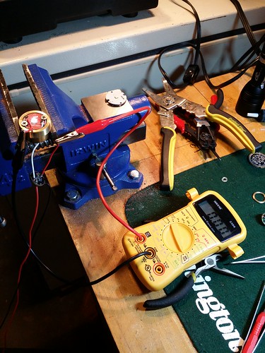
Sure looks like v013. Could it be an unplated via? I suppose a continuity test from pin 5 to one of the top side chips would tell us something. Some alcohol and a toothbrush would help too.
v013
Please flash the current stock STAR_off_time firmware. The stock output pin is Pin6, the pin which is hooked up to 7x. That will quickly determine whether it’s a firmware issue.
I flashed the standard star_offtime originally without changing anything. It acted pretty erratically - switched modes constantly, several times per second. I figured it was because it was looking for the moon star and since that’s connected to a 7135 it was constantly changing the number of modes. But my understanding of how the firmware works is still pretty rudimentary so that could be totally wrong.
I’ve got a second driver built with the same edited star_offtime… gonna hook that up later tonight to see what it does. If it works, that’d mean there’s a hardware issue with my first driver.
It shouldn’t be looking for a solderable star on the other PWM channel… if it is, it’s a rather old version of STAR or you’ve got dual PWM disabled.
You can find the latest version at JonnyC’s site or at my code repo (linked in my sig).
ToyKeeper, that’s exactly what we are talking about. I specifically recommended that grantman321 flash with dual_pwm_start disabled in order to see what happened.
Grantman321, the initial setup phase which looks for stars only happens once each time the flashlight is turned on (eg power cycled). Once it’s up and running it does not matter what’s on that pin.
Gotcha. Well in that case I’ve definitely got something going on with the components. I flashed the newest star_offtime to it initially and it didn’t work anywhere close to right. Lemme check another driver I’ve built to see what it does. It’s also running the firmware I put up on pastebin as well.
Sounds good. If the other driver works I’d start by removing all your 7135s. One at a time if you want…
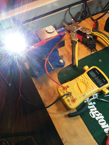
Welp driver #2 works perfectly. Low mode doesn’t even register on the DMM:
And high mode pulls between 3.00A and 3.02A:
I reckon it’s time to pull 7135s off the first one. Or maybe just salvage parts and chunk it. It’s pretty beat up.
I doubt that there’s anything really wrong with the PCB. I’d probably strip it and rebuild it, although I might throw out the 7135s. Or just check them all for shorts really quickly after I stripped it. If they don’t short then I doubt they are causing the problem.
Thank y’all so much for your help. Sorry it was somewhat of a wild goose chase. Haven’t decided yet what to do with driver #1… may end up fixing it, also might just salvage components and put them on another driver board. That one’s a little beat up and crusty with solder flux everywhere (from going in/out of brass C8 pills when testing).
Pretty psyched to have one of these working. Haven’t yet stuck it in a flashlight. Working on these has been somewhat on the back burner while I mess around with some other projects.
What LVP numbers should I be using with a 19k resistor to be somewhat conservative?
There is no need to guess about the LVP numbers. You can simply measure it. I have a firmware called battcheck which blinks out the raw ADC values, so you can just flash, measure a few voltages, plug them in to the firmware you want, then reflash.
So you can set the ADC values according to the internal voltage of a given mcu since they tend to vary 10% or more?
Not to be pedantic, but they do not “tend to vary” as far as we know. They tend to be very consistent based on the information I’ve seen. They may vary plus or minus 10% IIRC - I assume that this probably happens in the case of a production line change (semiconductor materials sourcing change or etc). Hopefully you don’t feel that I’m jumping down your throat!
From what I’ve seen posted here it seems that the primary differences probably have more to do with PCB layout and passive component selection (resistors, diodes, etc).
In any case you can flash this on a chosen driver and get real values blinked out of it specific to that driver. ![]()
So in any case batt check would allow you to set the ADC values accordingly whether the differences were internal to that mcu or in the passive components of a particular build, is that right?
Go ahead and light me up, I’m like one of those inflated, weighted punching clowns. :zipper_mouth_face:
is there more info on that batt check fw? As in, how do I translate “number of blinks” into values in STAR?
Oh, um, the battcheck firmware is in my code repo, linked in my signature. Information on using it is in a comment at the top of the source file.
I just pushed some updates to it, because I realized it doesn’t handle zeroes very well. So, now it’ll do a quick dim flash to represent a zero digit, instead of doing no blinks at all.
In any case, I generally plug in a cell at 4.20V, watch the blinks (for ADC=185 it’ll do 1 blink, pause, 8 blinks, pause, 5 blinks, long pause, then re-measure and repeat with a new value)… and then I plug in a cell at 3.00V and watch the blinks again. One more at 3.60V as a sanity check, to make sure it’s following a pretty linear curve.
It’s great if you can measure each exact voltage directly, but if not, it’s still pretty accurate to estimate the values using a straight line crossing two known data points.
From those, it’s possible to closely estimate the ADC value at any desired voltage. Basically, calculate the number of ADC units per volt, and add or subtract that from a known value until you get to a desired voltage.
For example, an AK-47 driver gave me ADC=174 at 4.00V and ADC=132 at 3.09V. I want values for 2.8V and 2.7V for LVP purposes.
(174-132) / (4.00-3.09) = 46.153846153846145 ADC units per 1.00V
Then, to get the ADC values for 2.8V and 2.7V, I can do this…
132 - (46.153846153846146 * (3.09-2.8)) = 118.6 for 2.8V
132 - (46.153846153846146 * (3.09-2.7)) = 114.0 for 2.7V
And it’s basically the same approach to get any other desired voltage, like for the battery check mode. For a “4-bar” battery check mode I generally need values for 3.0V, 3.5V, 3.8V, 4.0V, and 4.2V.
I also added an offtime capacitor value dumping tool, to help with calibrating OTC timings.
Exactly right. ![]()
Yes, take a look at the comments at the top of the C file. It simply blinks out the decimal number like so: 251 would be
…
……
.
looks like TK is already on it though. ![]()
Good idea? Is the general idea that we hold the tailswitch in the off position for the desired amount of time and then scribble down what it blinks out and adjust from there? Hmm.