During the Wallbuys New Years Sale, I picked up three of the 10W LED floodlights for $8.45 (regular price was $11.27).

I've seen similar products sold online for around $16 so I had to jump on this, even if the only good part is the enclosure. From what I have seen so far, they are well worth the sale price and there's room for improvement (check the first reply for some modding tips). it's not a bad looking light and the overall build seems good and durable. The lens is made of thick (4mm) glass (unsure if it's tempered). All external fasteners are made of stainless steel and there are weather sealing gaskets at every joint. The units that are built properly should handle any weather condition. They do not appear to be good enough for submersible use, however.
Product Specs from Wallbuys.com (SKU 5977)
- 10W 7000K 900LM High Powered Flood Light/Projection Lamp (100~265V)
- Silver grey shell
- Super bright: 850~900 lm
- Boast long service time
- Rated voltage:100-265
- 3-pin flat plug
- The whole weight: 480g (include package)
Packing dimensions:12cm( L )*9cm( W )*9.5cm( H )
size:12*9*9.5
The lights were packaged in a plain white box with no markings.

Out of the box, you get the enclosure with mounting bracket and Australia/Asia type power cord. Other parts of the world will need an adapter or change the cord. No user manual or installation instructions were included.

All three were fully functional out of the box. Only one had a small problem. The weather sealing grommet around the power cord was pinched and is not sealing the hole properly. I believe I can fix this, but I should not have to. It does indicate that the manufacturer may have some quality control/inspection issues.

OK, now for the fun stuff; tear down time!
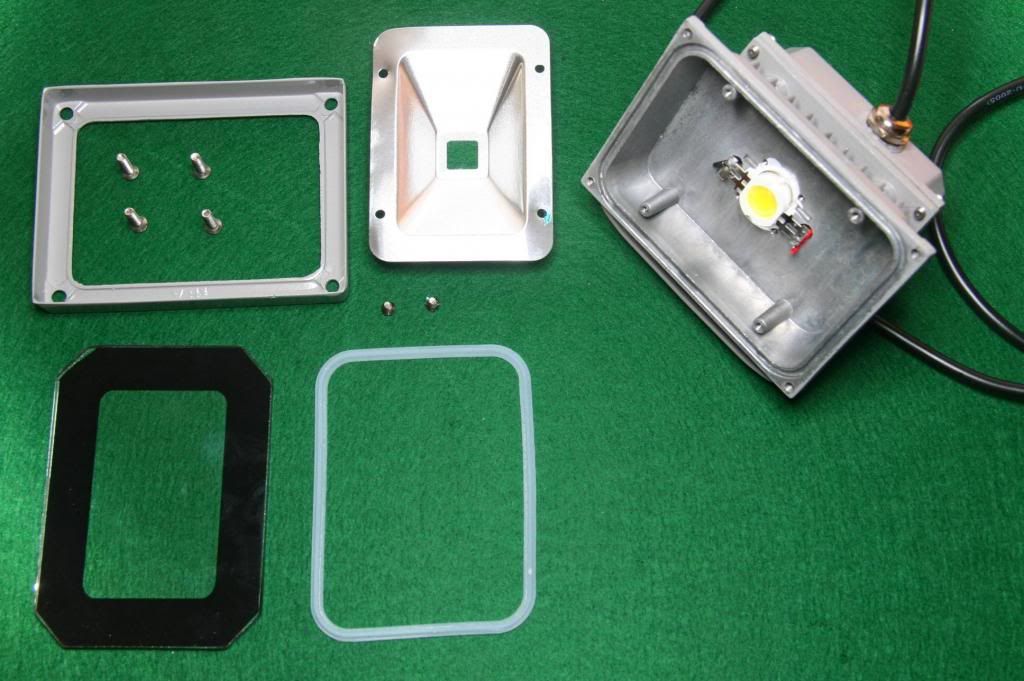
Opening up the front means removing the four front bezel screws. This allows removal of the bezel, lens, gasket, and reflector which is held in by two screws. We now have access to the emitter.

The emitter is held in place by pressure from the reflector. It also has adequate thermal compound and should be conducting heat away nicely. I did notice that this enclosure is designed for the square-type 10W emitters; there are four tapped holes perfectly spaced for that purpose (check the mod comment below for an example). Note that the reflector is also perfectly cut for this as well.

The wires from the emitter snake through two holes that connect to the driver compartment at the back. This also opens up by removing four screws. The driver connects to the emitter via a two-pin captive connector, which allows the two enclosure pieces to be separated. I included a 14500 cell in this shot to give a sense of scale.

Right away, I noticed a serious safety issue with this light; the earth ground conductor from the power cord is not connected to the metal chassis. This would likely fail every safety lab approval in any country. If the AC mains were to somehow contact the chassis, it would become live and present a serious shock hazard. In one of my lights, I used the inner grommet nut to fasten the ground wire to the chassis, but this was difficult to do and probably still not safety approved. The proper way is to have a separate metal screw in the chassis that the ground wire can be fastened to. I plan to add this before putting these in service.
Update: Upon further inspection, I noticed that the power wire gauge is very small. The sheathing states 0.5mm2 (~20awg), however it looks much smaller than that maybe 22 or 24. I am not up to speed on minimum wire gauges, however I have not seen products in North America with wire smaller than 18 gauge. This small wire is making it difficult to connect the wire to a ground screw without accidentally breaking it. I would recommend changing the power cord, especially if your jurisdiction requires a larger gauge wire.
The driver itself is enclosed inside a small plastic case to keep it from contacting the metal enclosure. I find that this might be restricting the air space for the driver and heat dissipation may be a concern (especially if modding). Adding some additional holes on the top and sides may help.
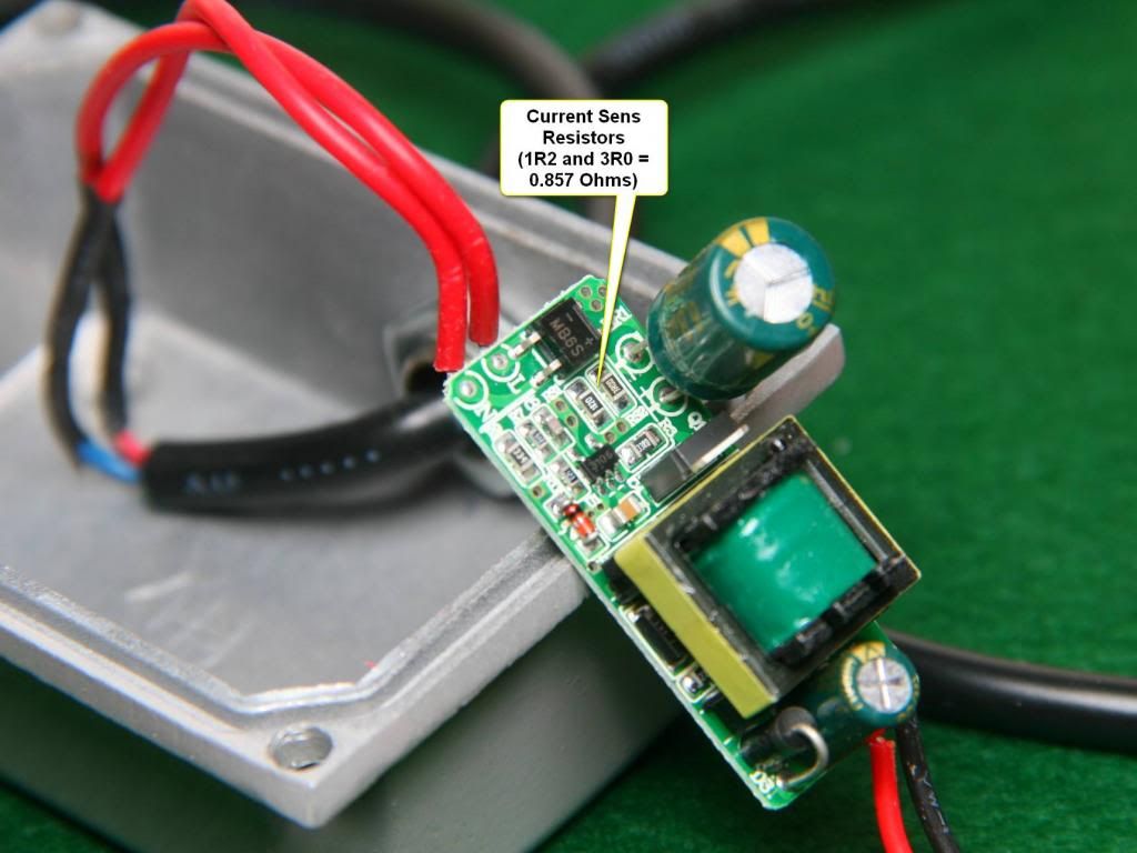
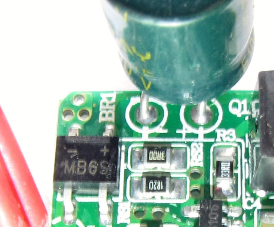
A close examination of the driver reveals the current sense resistors, located under the large electrolytic capacitor.

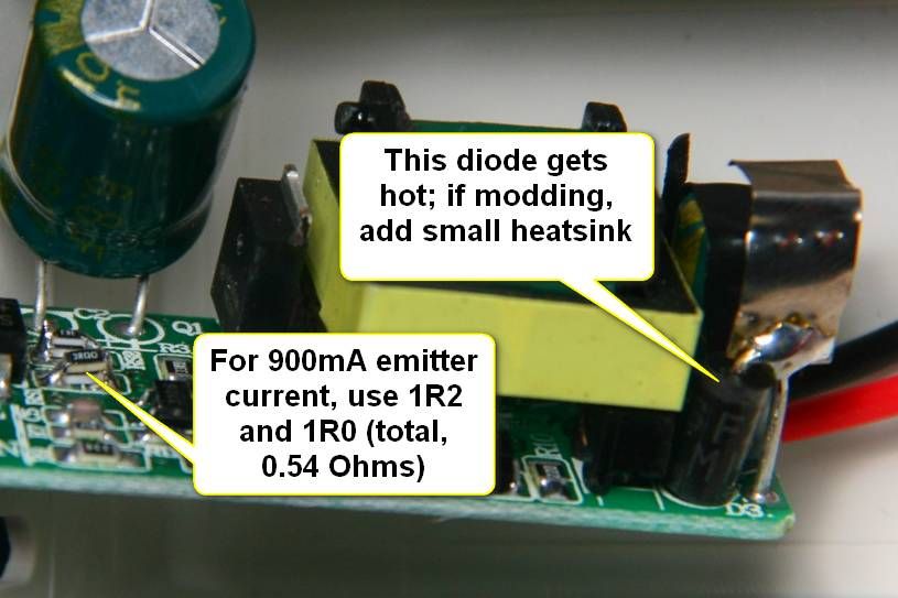
The stock unit comes with a 1R2 and 3R0 in parallel for 0.857 Ohms total. This gives about 600mA of emitter current for an output power of just under 6W. The Power in was measured as 7.2W (120V, 60Hz) for an efficiency of 83%. For a light that is rated at 10W, it's rather underdriven at stock. Luckily for the modders among us, there's an easy mod to correct it.
Light output measurements confirm the underdrive condition. The unit throws 417 lm OTF. This was just under half the minimum stated in the Wallbuys (likely came from the manufacturer) specs. Even with this, the unit can still light up a reasonable area; just don't buy this product depending on the manufacturers stated light output.
Thermal management was good, with the integrated heatsink/chassis quickly reaching a stable operating temperature (see table below). Driver temperature was not measured. One diode was noticed as rather hot, but at stock it should be OK.
Cautionary Note: Since this driver appears to be designed for 220V power grids and the current sens appears to be on the mains side, you should check if this mod is necessary by measuring emitter current before attempting any mods. it may output the proper current when running on a 220V supply. I have 220V access, but I have to drag everything out into my garage and I'm way to lazy to do that :)
Dimensions:
Width (Bezel): 115mm
Height (Bezel): 87mm
Depth (Bezel to back of enclosure): 80mm
Depth: (Bezel to mounting bracket): 103mm
Cord Length: Approx. 1m
Cord Plug Type: Australia / Asia type three-prong plug, 22 or 24 gauge wire
Reflector type: rectangular, aluminum
Lens: Glass, 4mm thick
Weight (including cord): 466g
Performance:
Power In: 7.2W
Power Out: 6.0W
Driver Efficiency: 83%
Light Output (no lens): 450 lm
Light Output (with lens): 417 lm
Light tint: Cool White
Thermal Management:
| Time | 0m | 5m | 10m | 15m | 20m | 25m |
| Temperature | 19C | 28.2C | 31.8C | 34.4C | 35.8C | 36.4C |
Relic's Conclusion
Overall, I like these little lights. They simply do the job for me (although I needed to mod it to get what I want, not a big deal for me; YMMV). Buyers looking for a 800-900 lumen light will be disappointed by the output. Even a mod to give the correct emitter current cannot come close to the manufacturer spec (see mod comment below). If you are comfortable with performing the safety fix (or brazen enough to use it as-is) and are OK with the actual light output, this light is very useable.
I would like to see Wallbuys check with the manufacturer about the earth ground wire.
Recommended for those willing to fix the earth ground and safety issue, or if Wallbuys has the issue addressed by the manufacturer. Otherwise, it may not be worth the risk.
Update: I also recommend a different power cord, something with a larger gauge wire.
Thanks for reading! searchID8934


