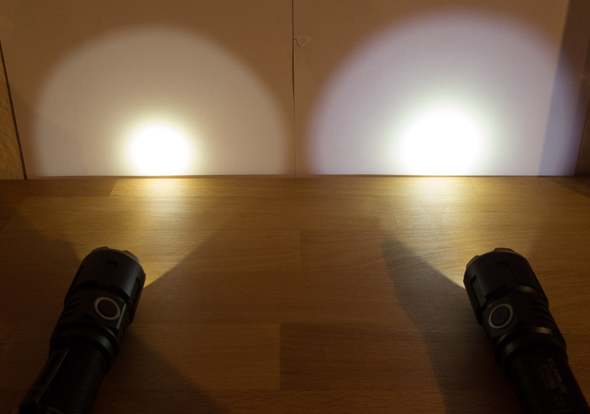
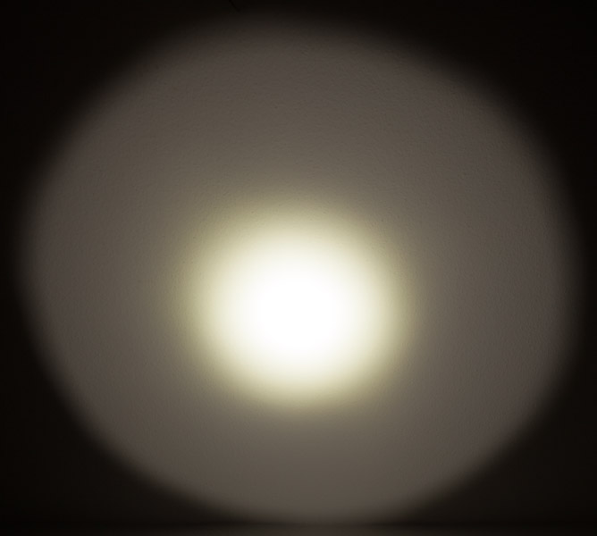
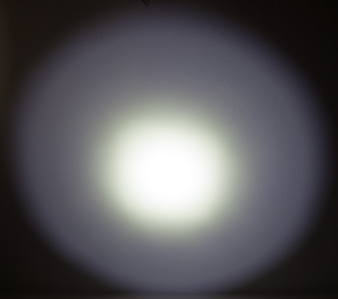
I received this light today I bought it on Banggood with freeme´s coupon code
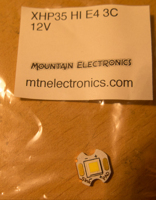
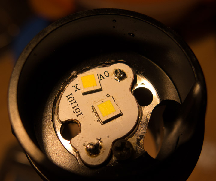
I was told that I got a new XHP35 HD version, but the old HI version is here now, so I will order a XHP35 HI E4 from mountain and open the light later
The light comes in a box.
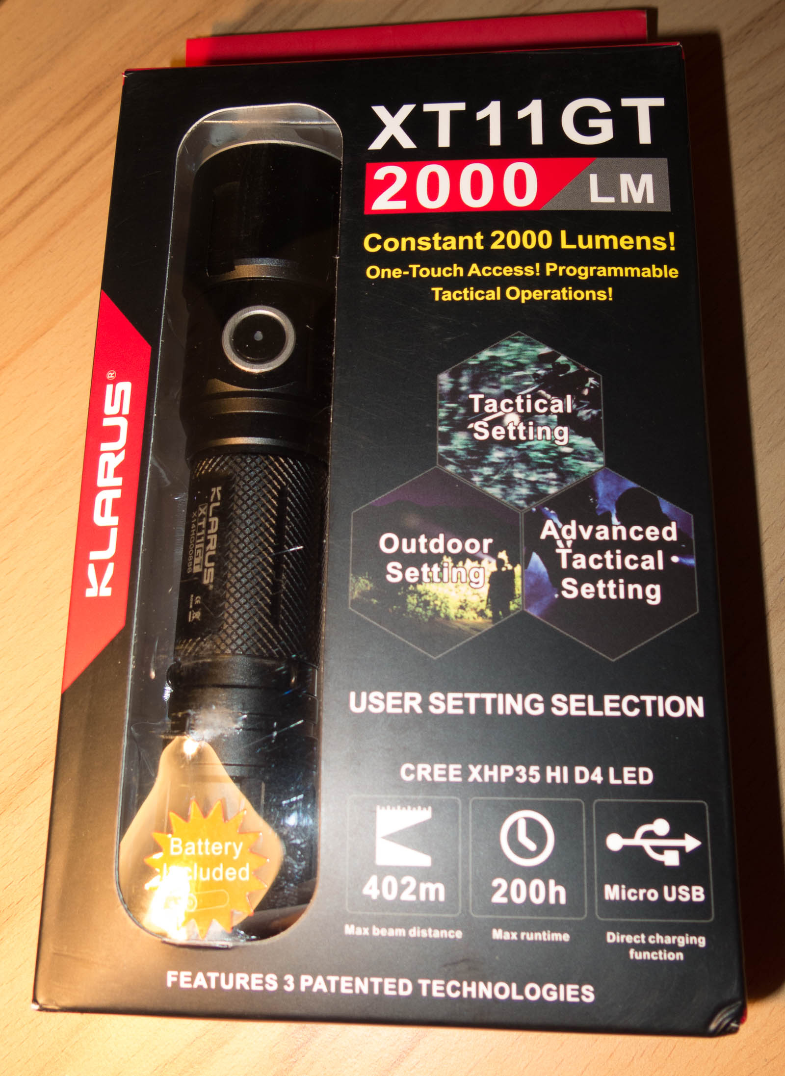
It contains
- the torch with pocket clip attached
- 3600mAh protected Battery inside the torch
on my sample there are no tapes isolating the battery so the parasitic drain will discharge it till the PCB shuts down
the label says there should be some so it might have been forgotten in my light, the battery was at a useable voltage
- holster
- Strap for the light
- instruction manual
- 1m USB cable, very thick so it should have very few voltage drop
- a ring for anti roll and Lanyard hole, even if the tail has a lanyard hole
- Klarus design promotion card, so if your suggestion leads to a new product you get one for free
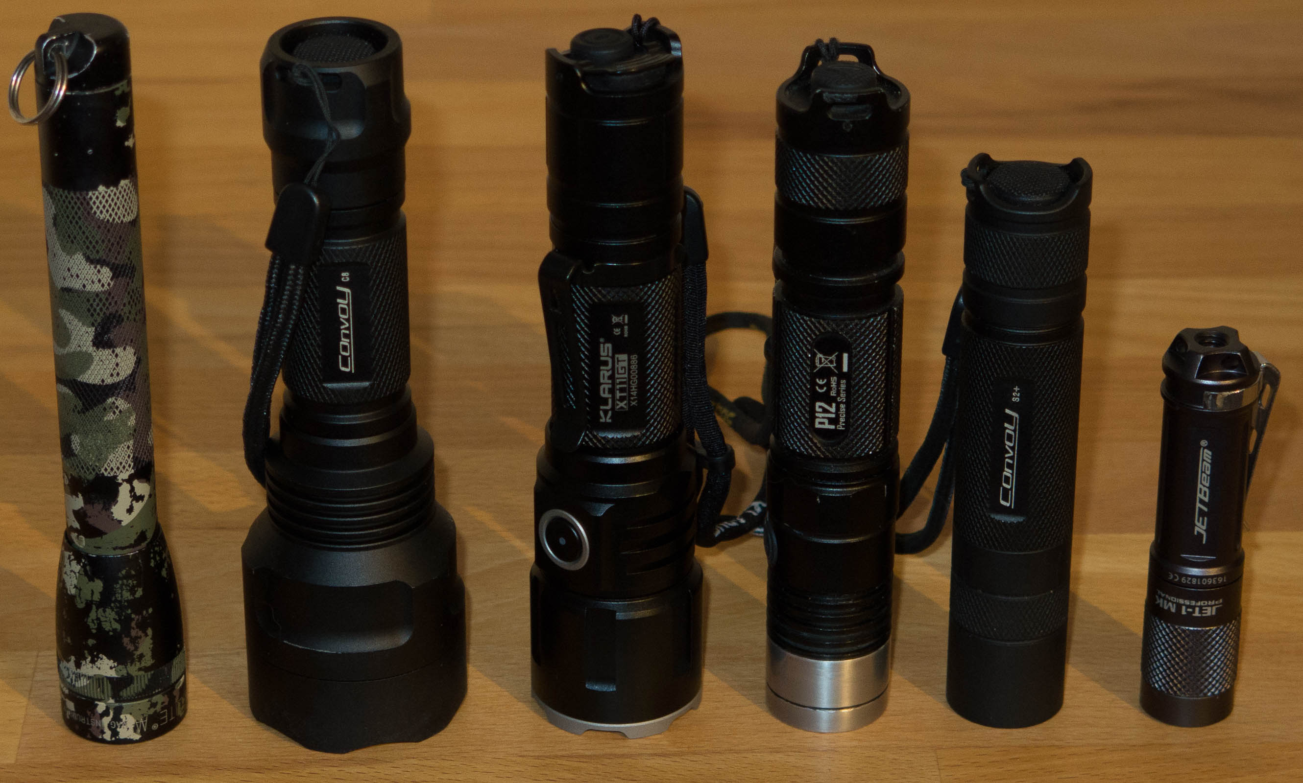
The light has a very good build quality.
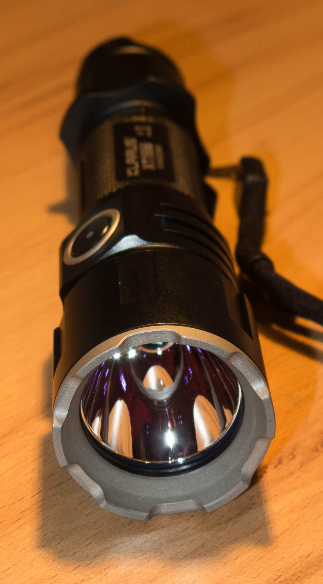
So now the most interesting part for the XT11GT
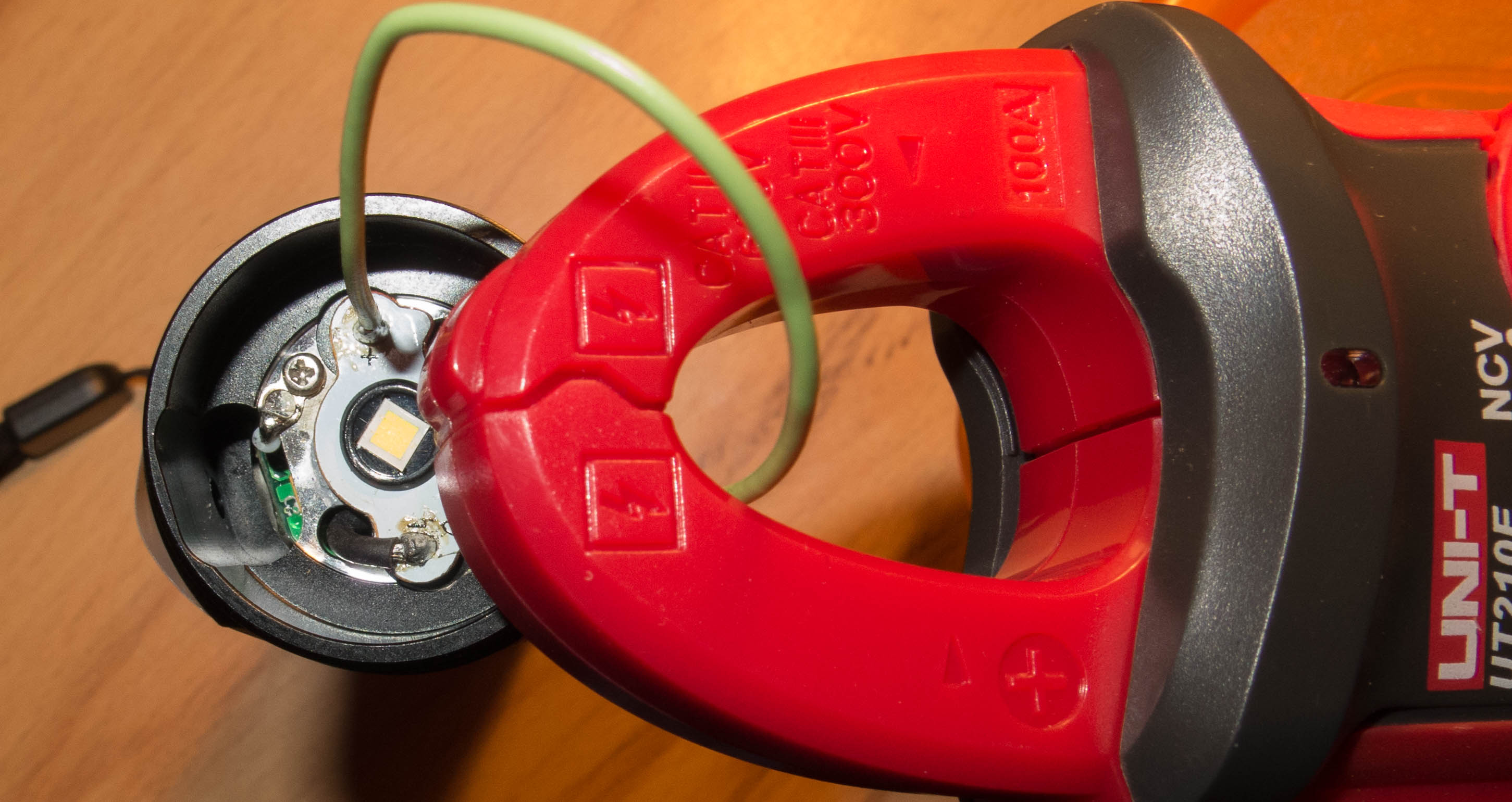
The XHP35 HI D4 LED runs with 1.38A
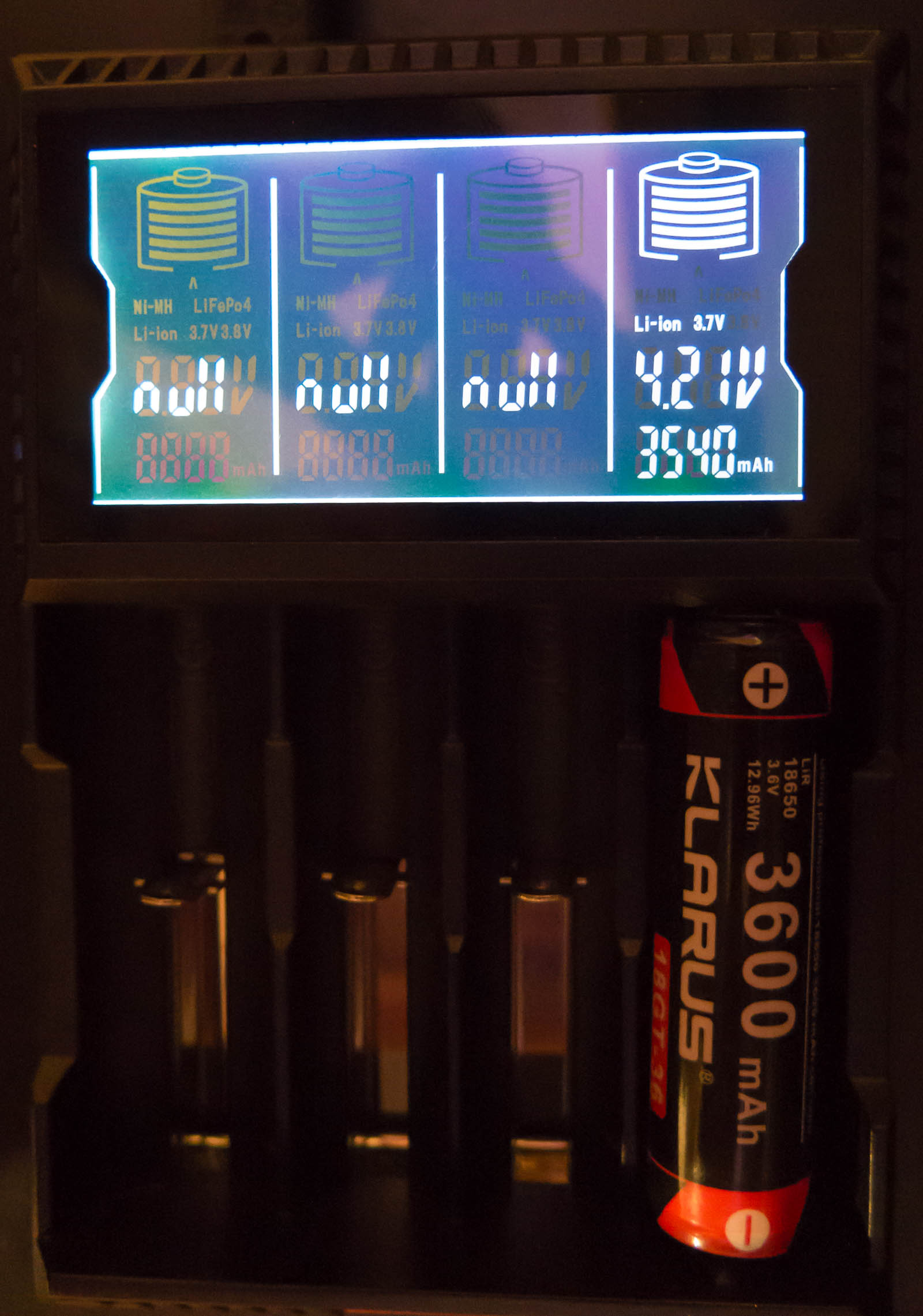
The battery seems to be 3500mAh type, discharged it to 2.5V idle 2.54V
There is an additional inner tube to control the light with the toggle,
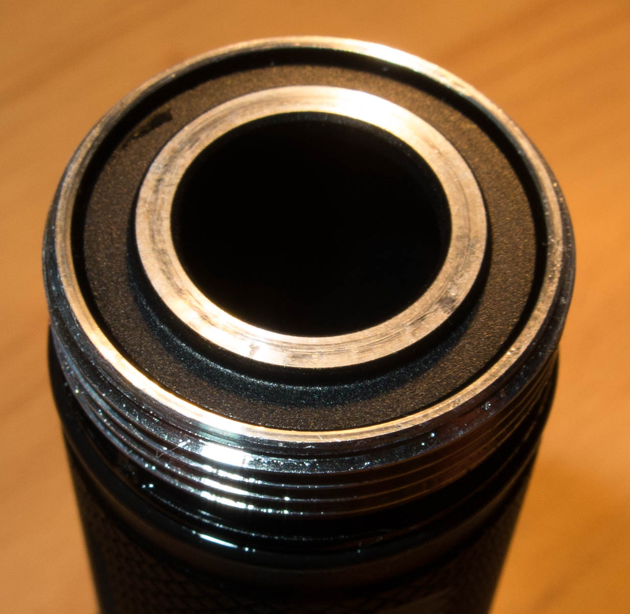
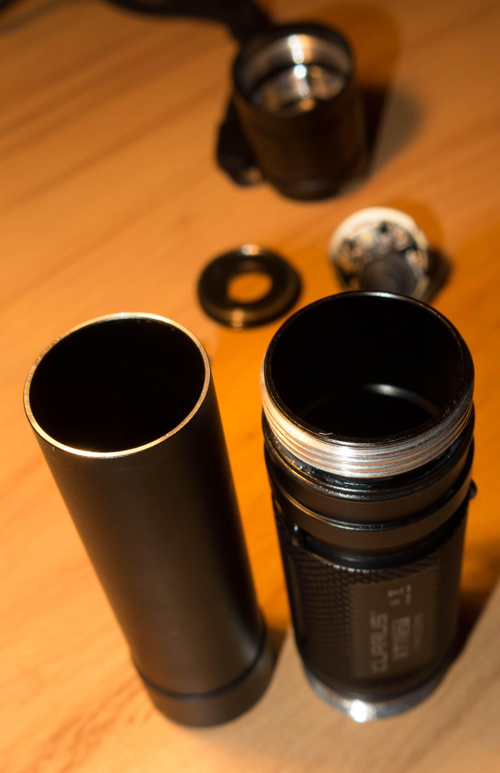
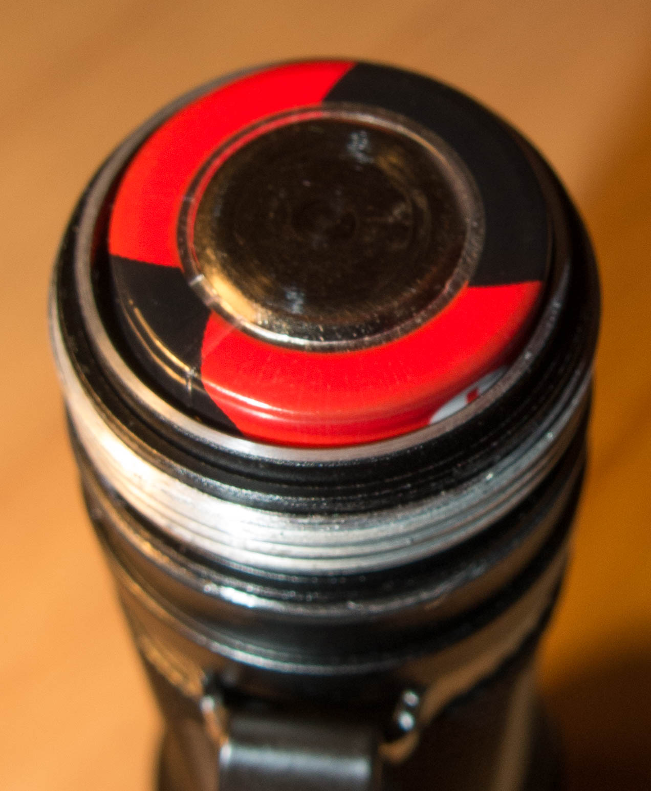
as there is electronic stuff in the tail cap I can’t measure the current like in a normal light
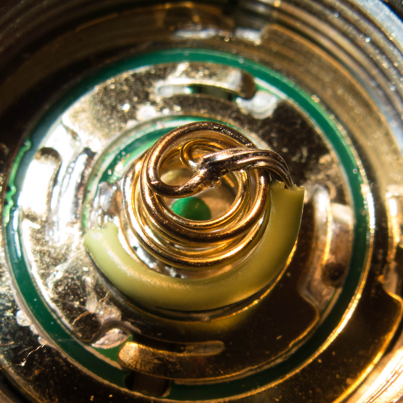
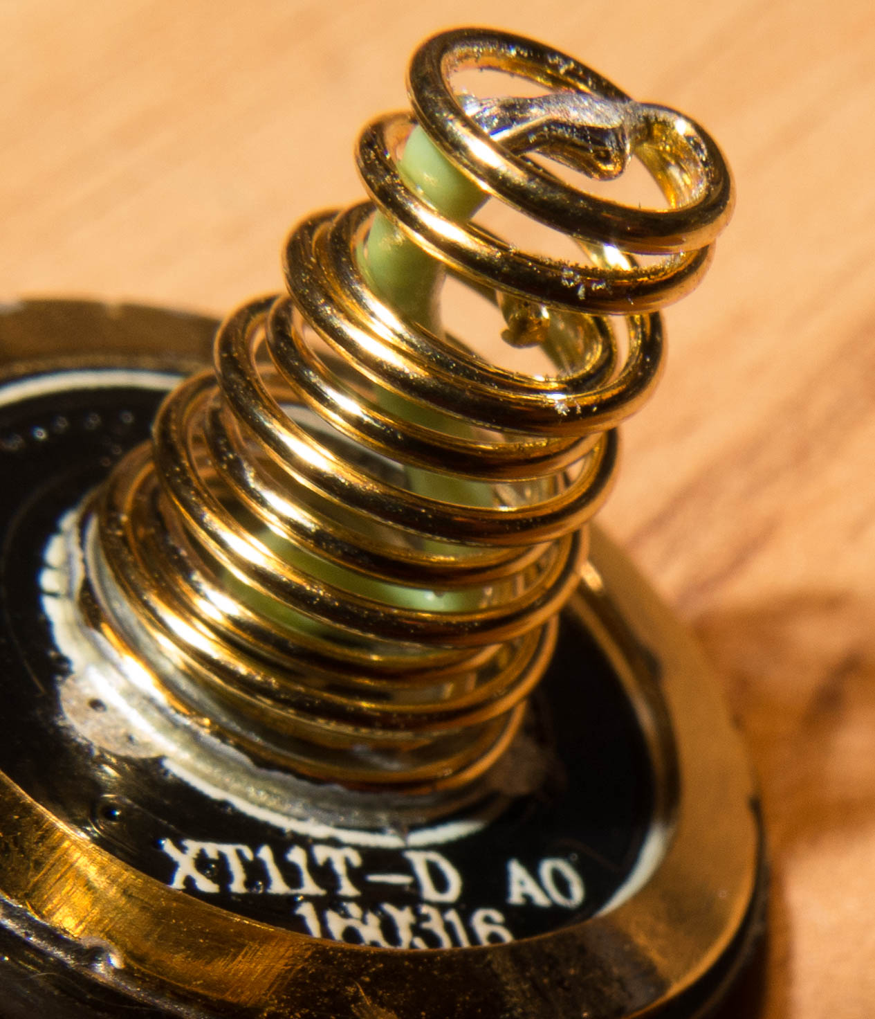
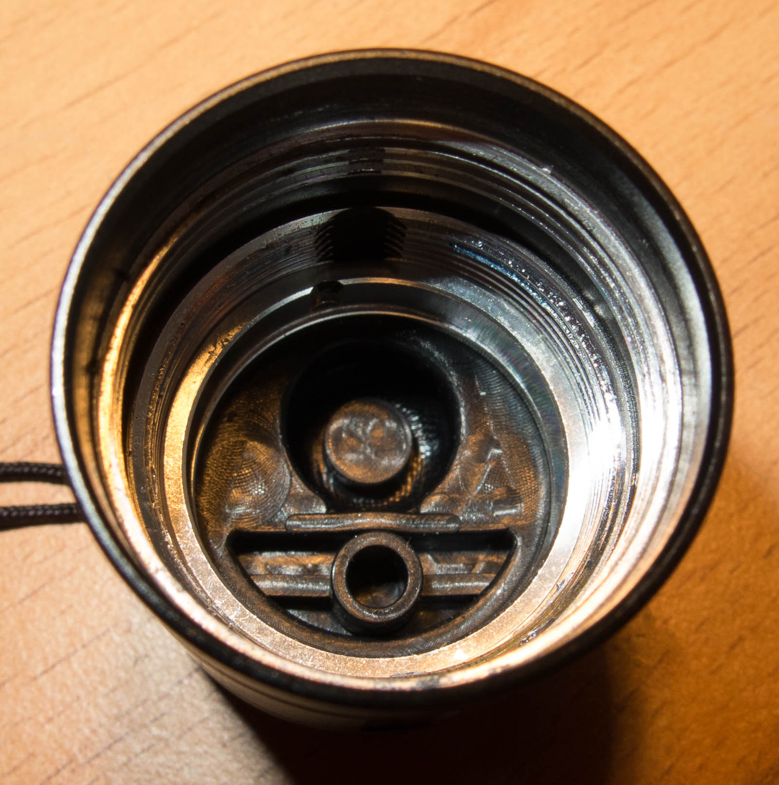
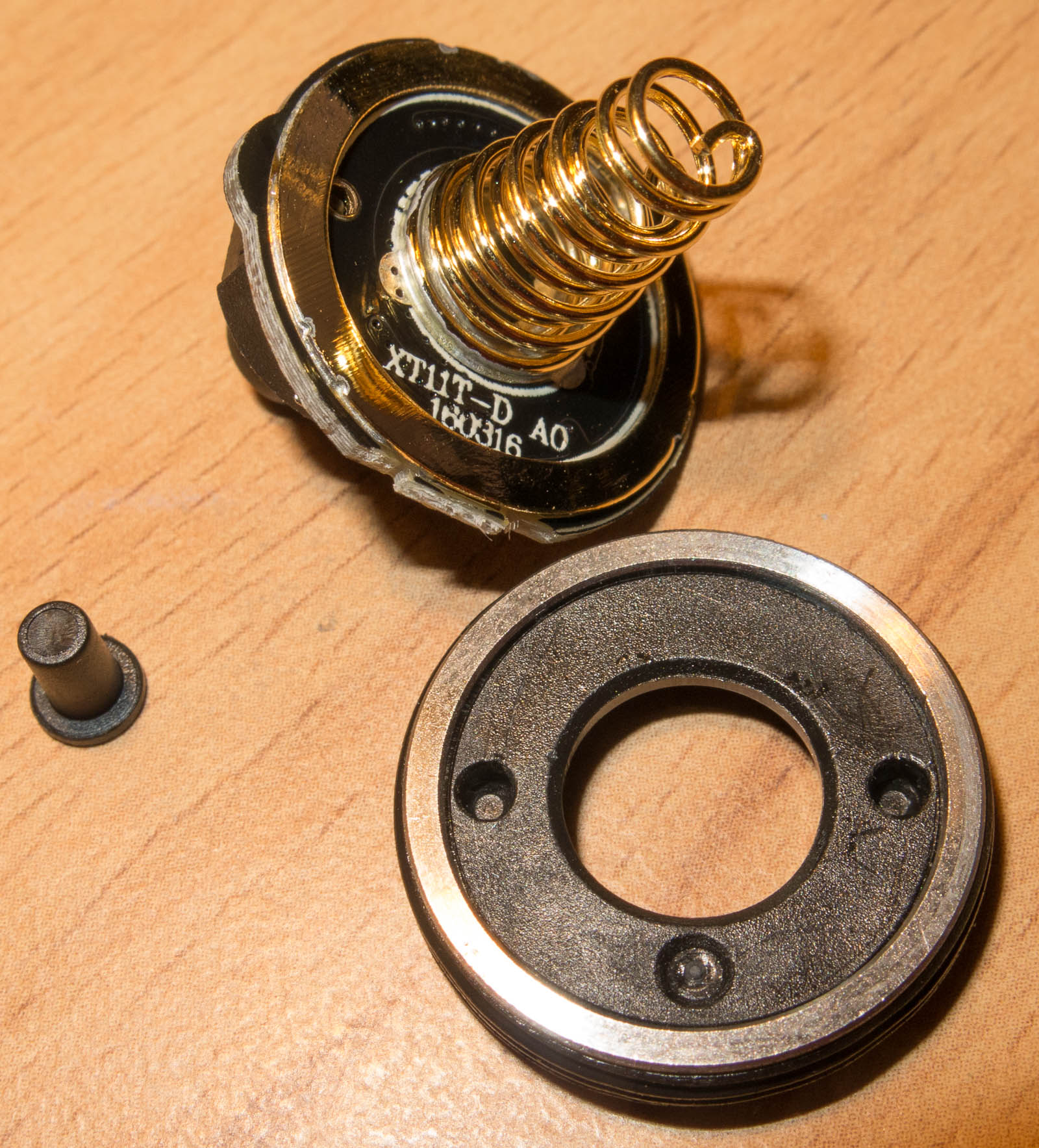
It has dual springs for high currents, the voltage drop measured is low for a 12mm and 6mm spring but can be improved a lot by bypass.
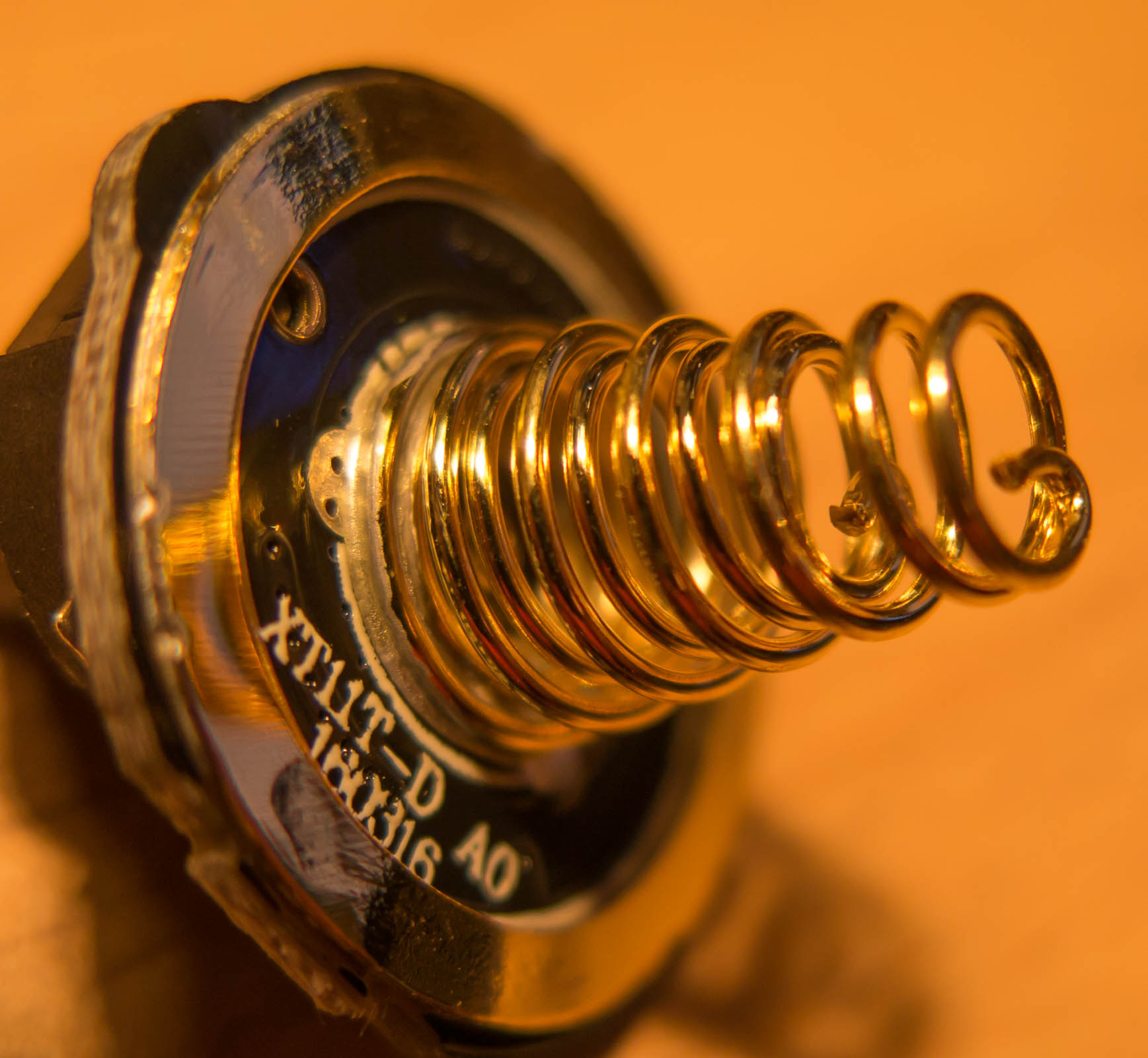
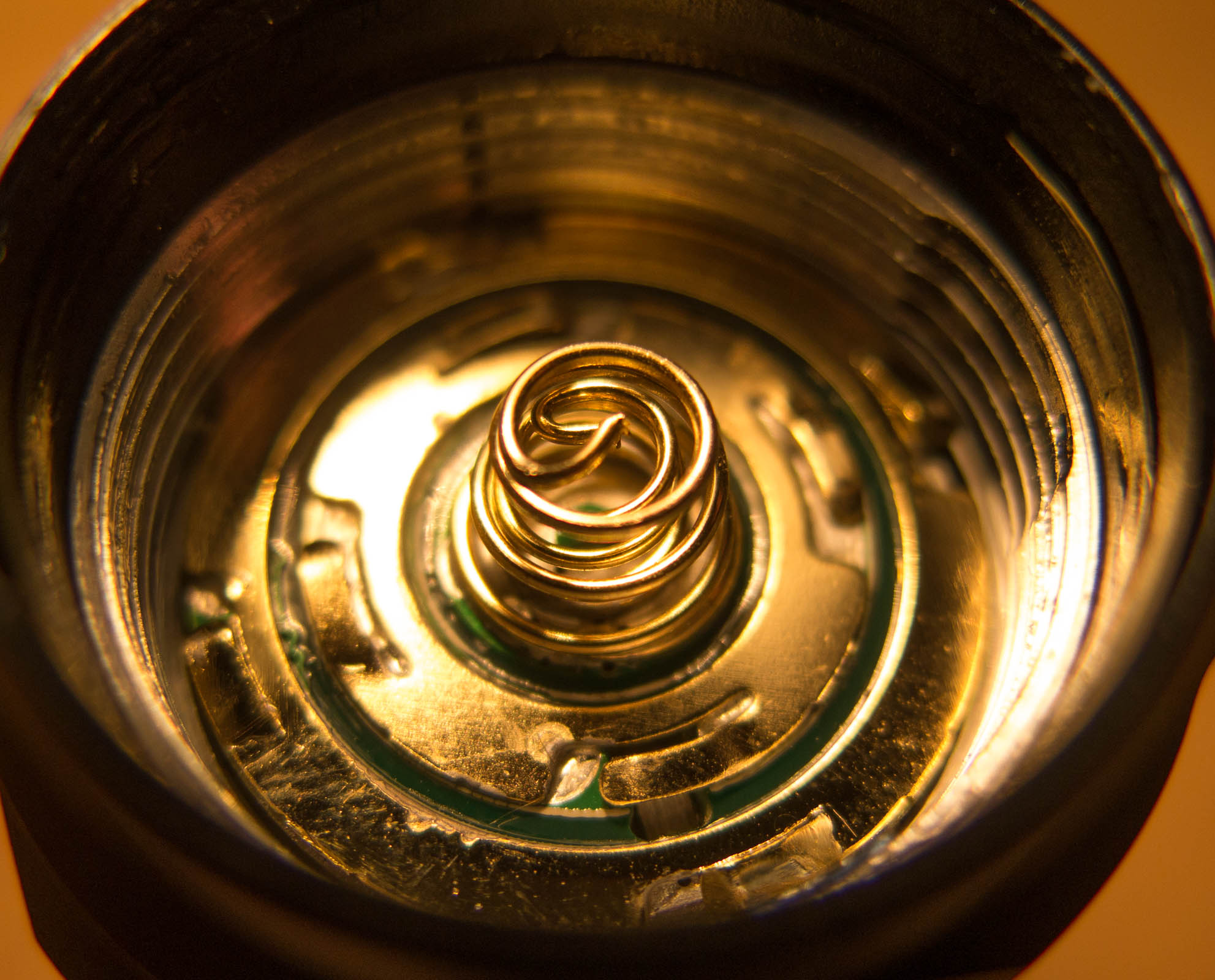
I could measure for the tail cap spring 180mV and head spring 95mV drop at 5A.
With my Spring bypass 0.5mm²
17.5mV instead of 180mV @5A on tail spring
13mV instead of 95mV at 5A for driver spring
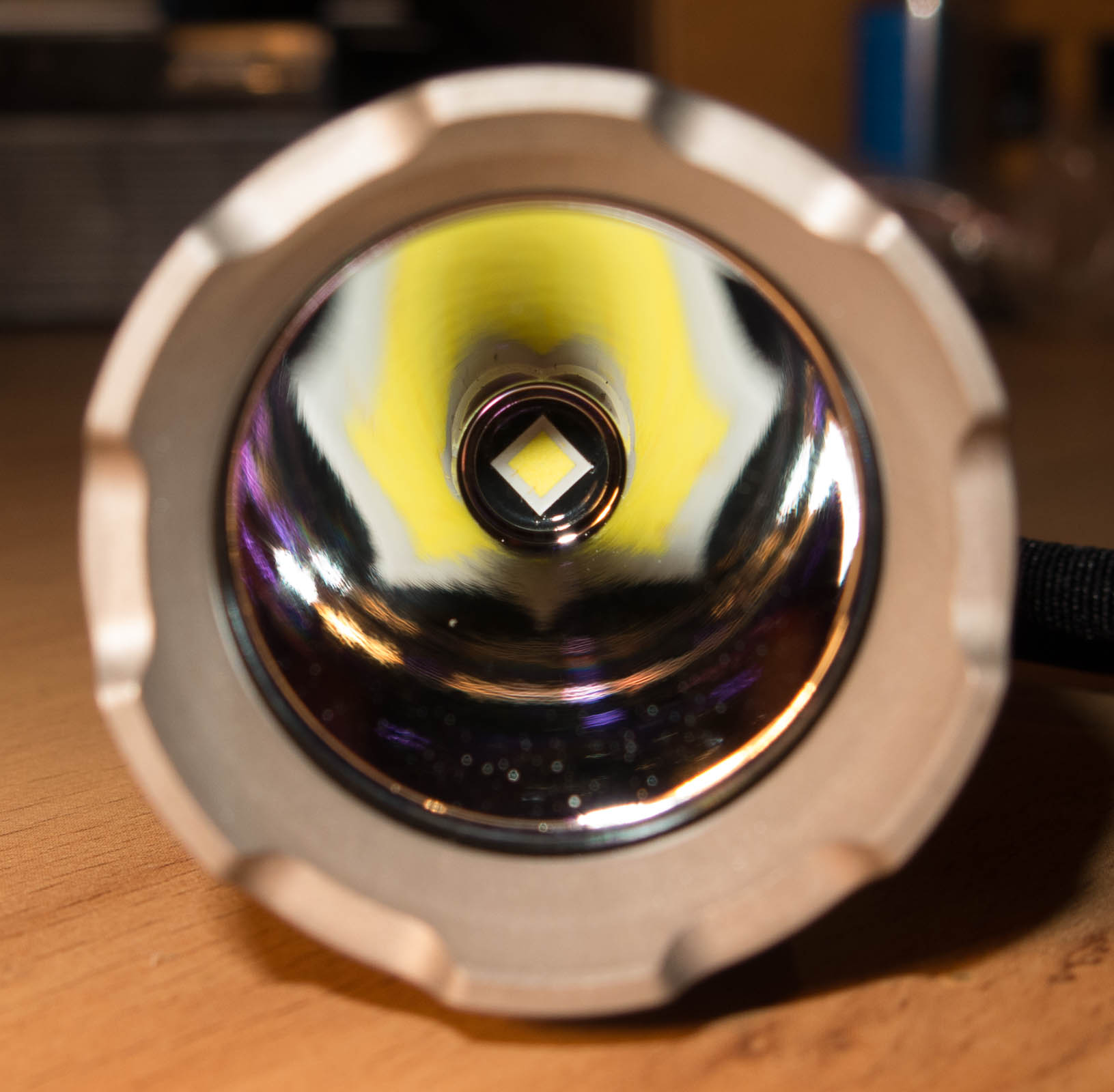
The LED is between cool and neutral white, but has only a very little blue tint, my Nitecore P12 is cooler and worse tint.
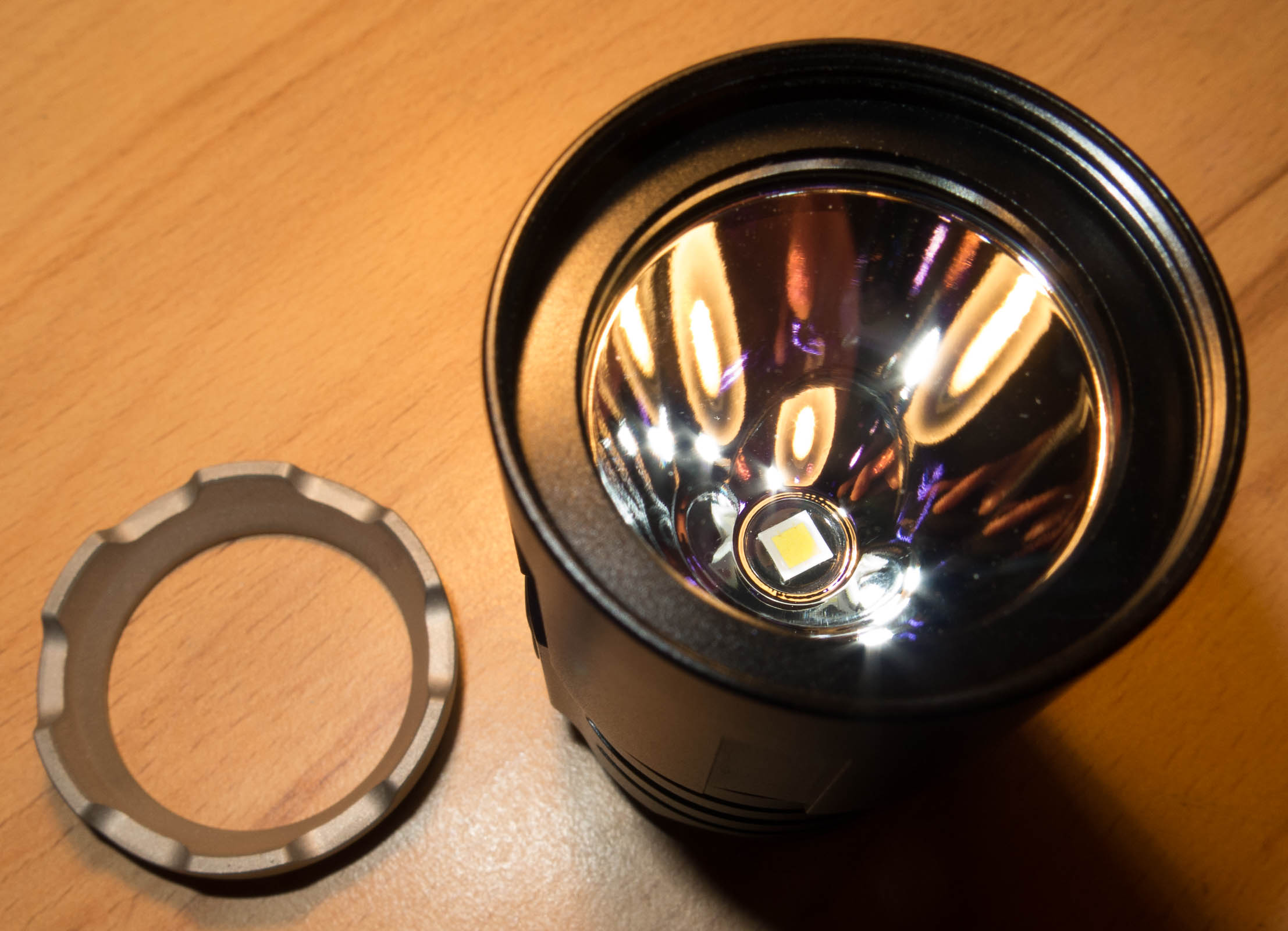
The reflector is almost perfect there is one particle on it which might be just dirt.
The knurling has good grip.
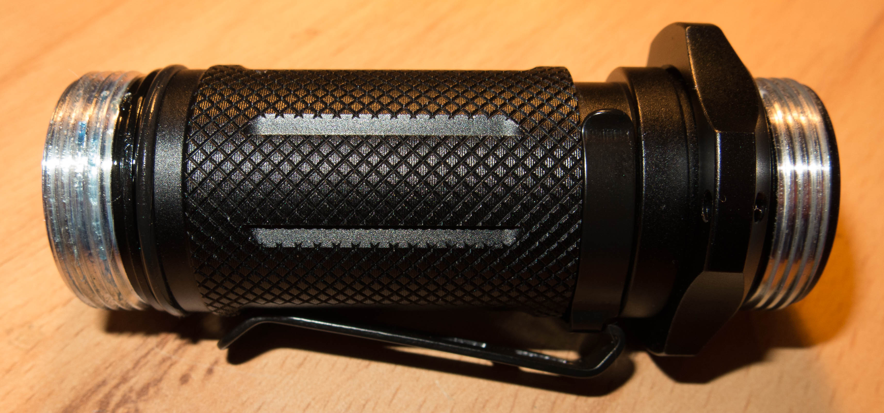
The bezel is remove able, but unfortinually no black non attack bezel in the box and with the thread open it looks odd.
The light has 3 switches, which might be odd and too much for an easy handling, but quite the opposite is the case!
You can control the whole light with the side switch in tactical and outdoor setting
if you don’t want to use it you can put it in lockout mode and control the whole light with the two tail switches.
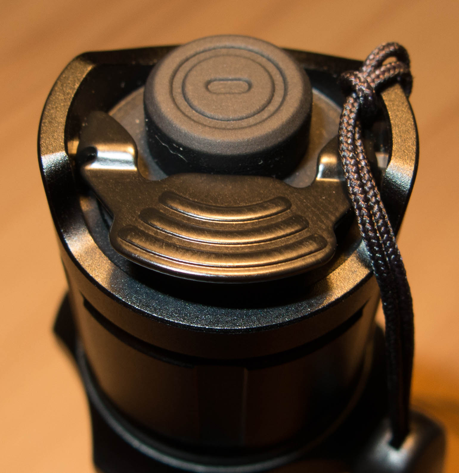
The tail has a forward clicky switch and a toggle paddle e-switch.
The user interface is pretty complex but has a very broad and good usefulness if you know it.
There are 3 main settings you preset.
First is tactical setting, 2. outdoor setting third advanced tactical setting.
I will start with the tactical setting, which is pretty much what I want.
If the light is off
- you can instantly access Strobe with the paddle, momentary and over 2 seconds it gets locked, tap again and the light is off.
- momentary turbo mode with main switch, fully press to turn on the light
- short tap on side switch for instant turbo
- long tap on side switch for moonlight
- double Tap side switch for strobe
When the light is on from e-switch
- tap side switch to toggle modes in reverse order Turbo-High-Med-Low
- hold side switch to turn light off
- tap toggle to switch between Turbo-High-Low no medium
- hold toggle switch to access strobe, as long as you hold its 10Hz strobe, when you release after 2 seconds fast and slow strobe is locked in
below 2 seconds release and the light is off (so your enemy is blinded and you can get away without the light being on)
tap e-switch or toggle to turn light off
tap forward switch for momentary, when you release it light is off
- forward clicky gets you to turbo no matter which mode the light was in
tap toggle to switch modes
0.5s hold toggle for strobe after 2 seconds strobe gets locked in
If the light is on from forward clicky you can’t turn the light off with the side switch.
Outdoor Setting
In Outdoor settings the toggle doesn’t do strobe and changes all 4 modes.
- use toggle from off you get in low mode momentary above 1 second keeps low mode
if light is on long press on toggle turns light off
- sideswitch keeps the same
Advanced Tactical mode
the light knows only Turbo and Strobe, side switch has no function.
The UI is almost perfect for any use I can imagine.
To switch mode groups hold side switch 10 seconds it starts to strobe fast at low intensity
tap toggle, light signals one flash for tactical, two for outdoor and 3 for adv. tactical mode.
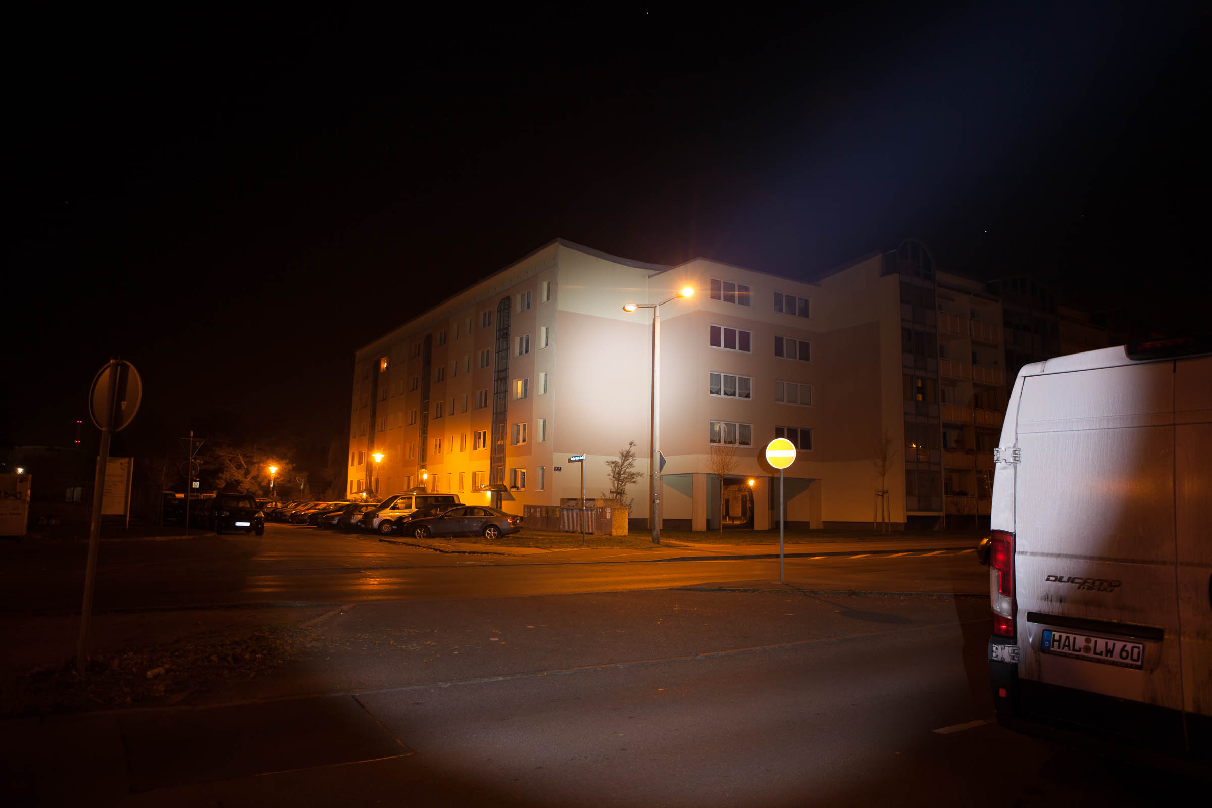
Beamshots EOS 5D Mk II - 0.5s f2.8 ISO400 4800K
Distance is measured 50m to center of spot
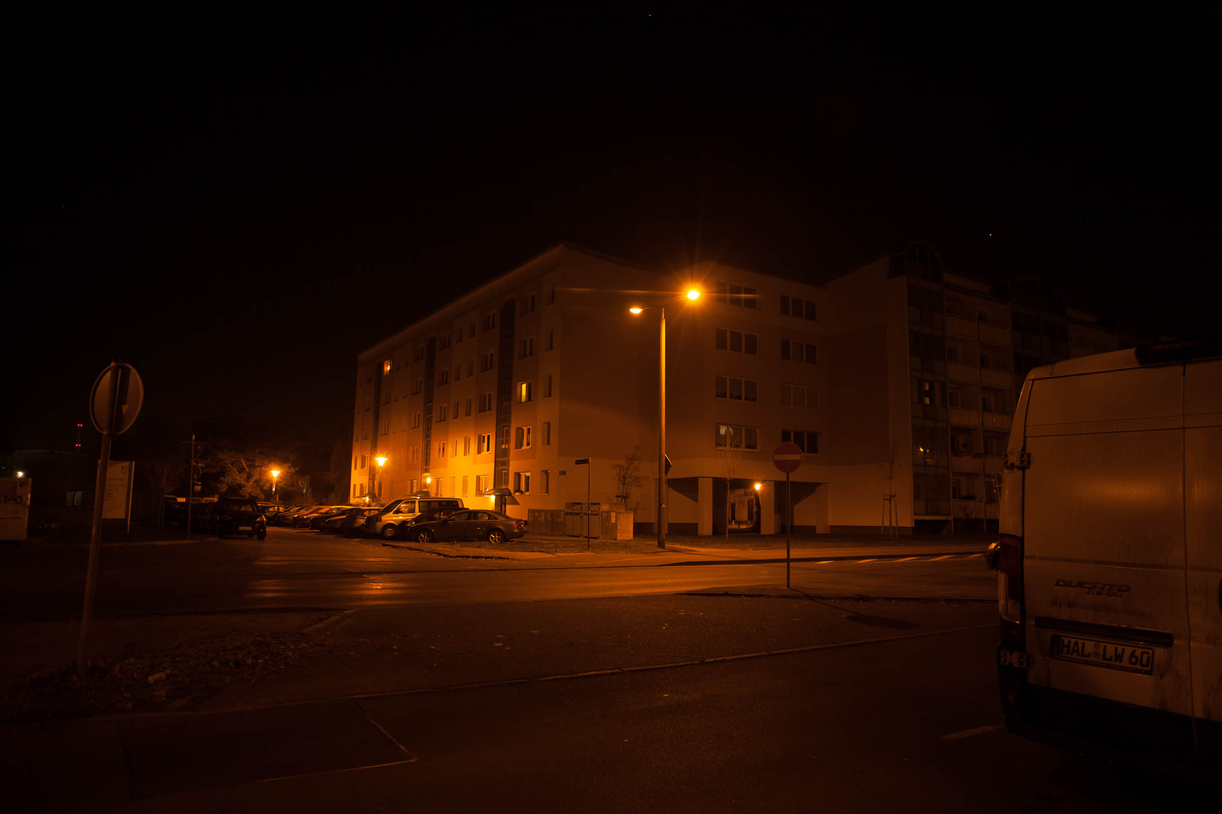
Convoy C8 XPL HI V2-1A 7135*10 3.6A
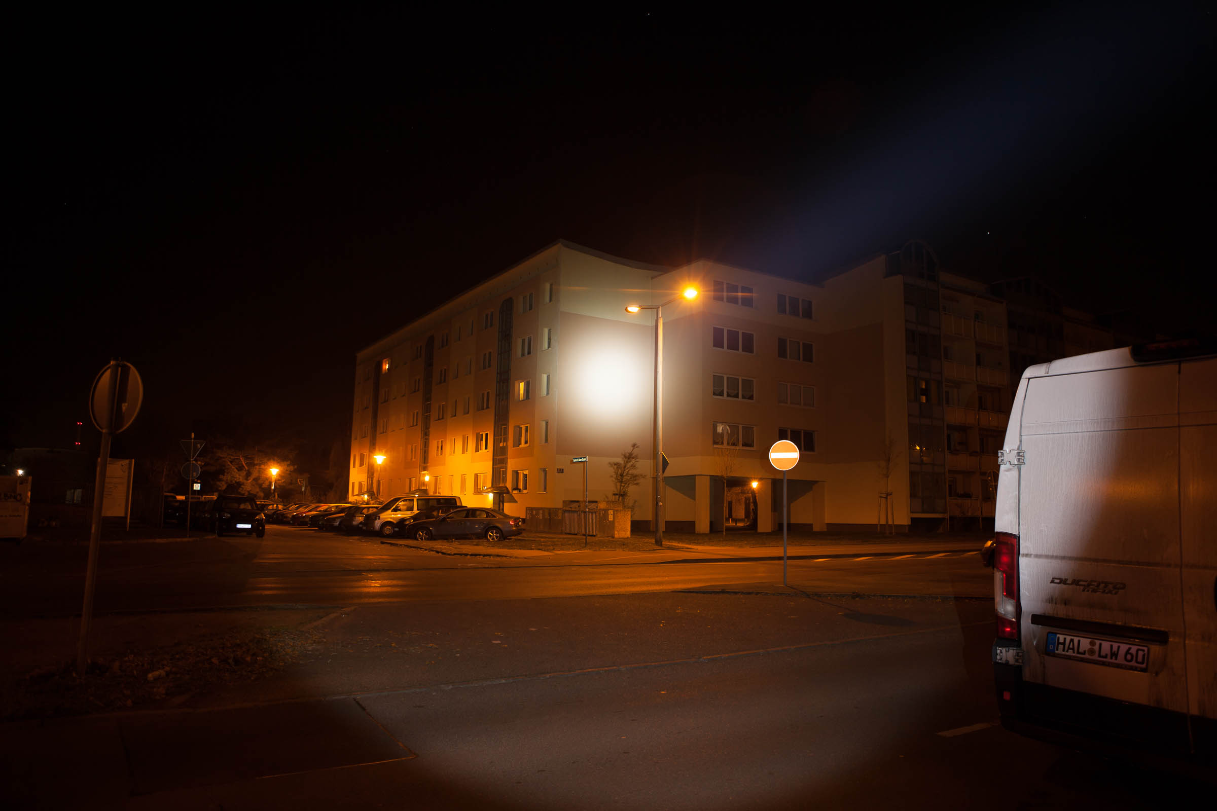
Klarus XT11GT XHP HI D4
I opened up the Klarus XT11GT head
I heated the head to about 50°C and tried it and it got loose with not so much force, but not easy
Using wood to protect it, so no damage was done
the fact that the head is not a plane cylinder gave pretty good grip in the wood
Same with the part containing driver and LED as its not a cylinder easy to screw it
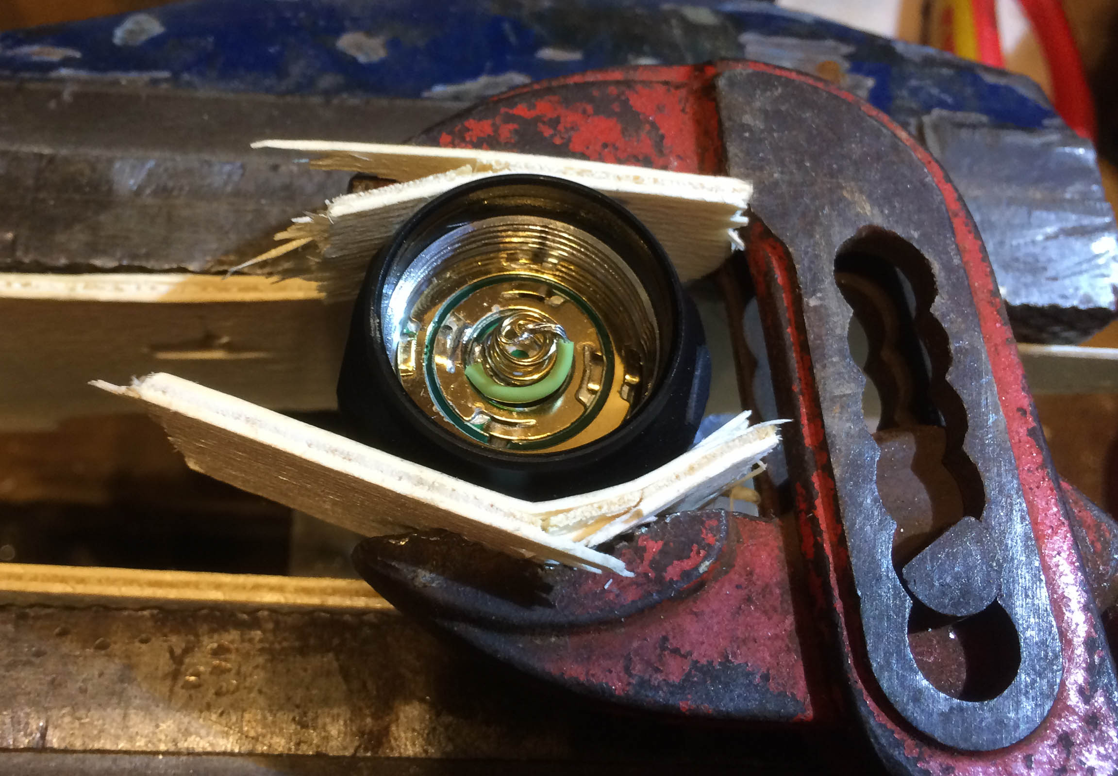
Instantly protecting the refelctor for dust, even if there is one particle inside I will try to get out later
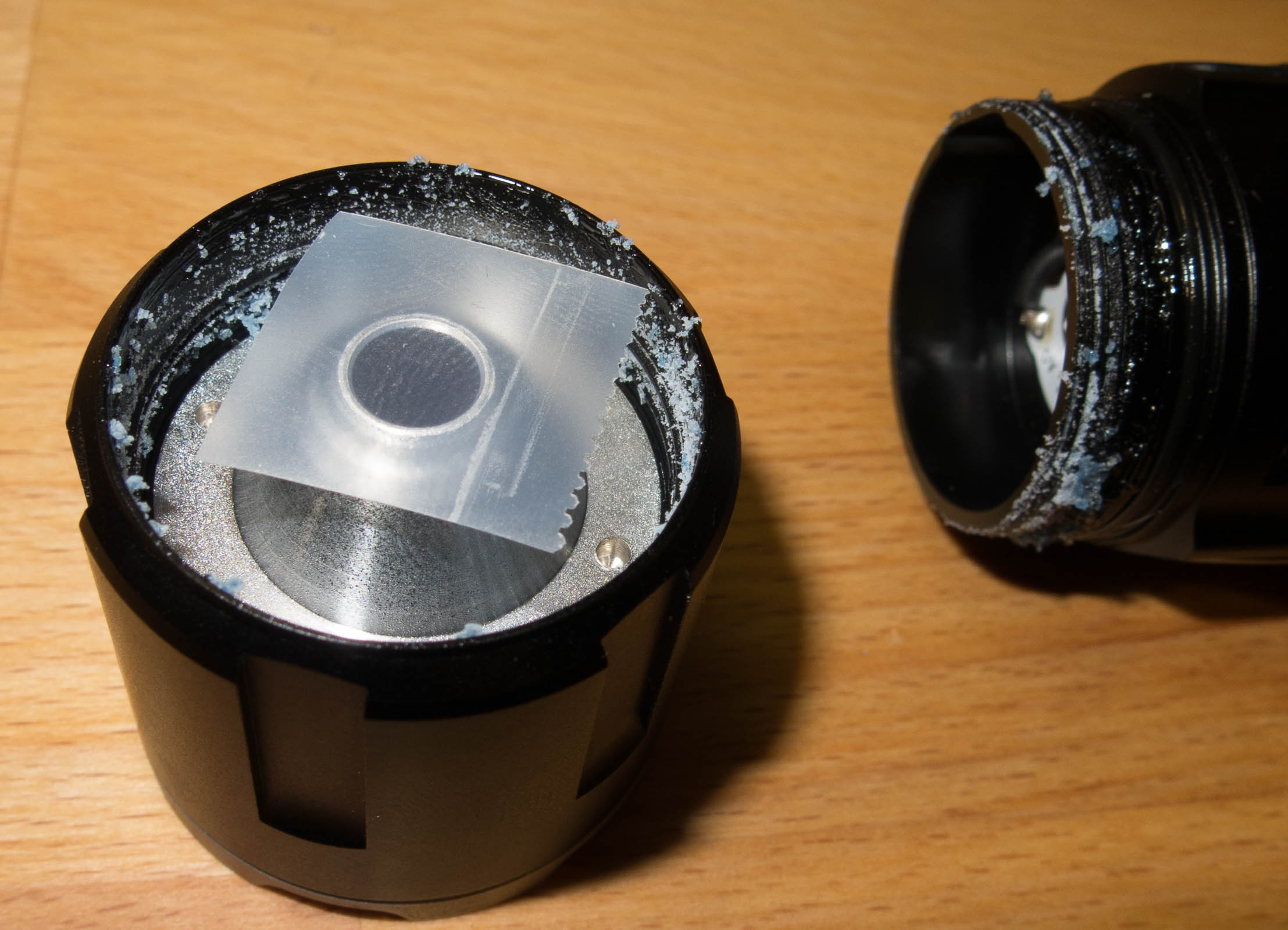
they use a custom shaped MCPCB,
looks like DTP but there is no open solder to measure it without desolder the LED
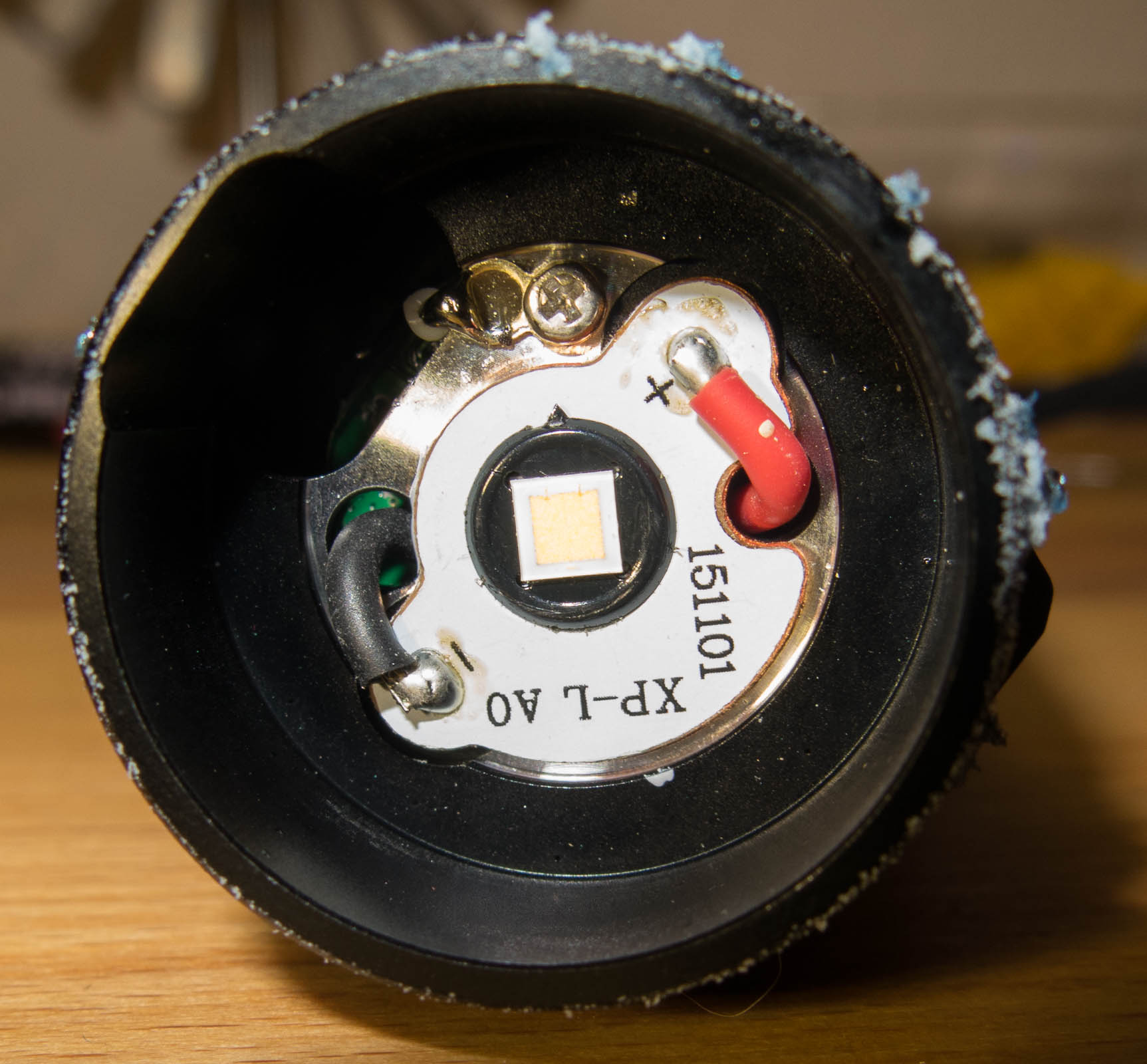
the driver needs a connection the the body
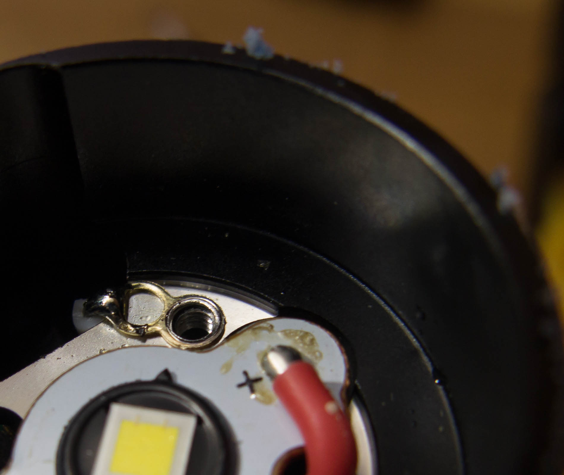
the MCPCB has something looking like a very thin Arctic Silver heat paste underneath
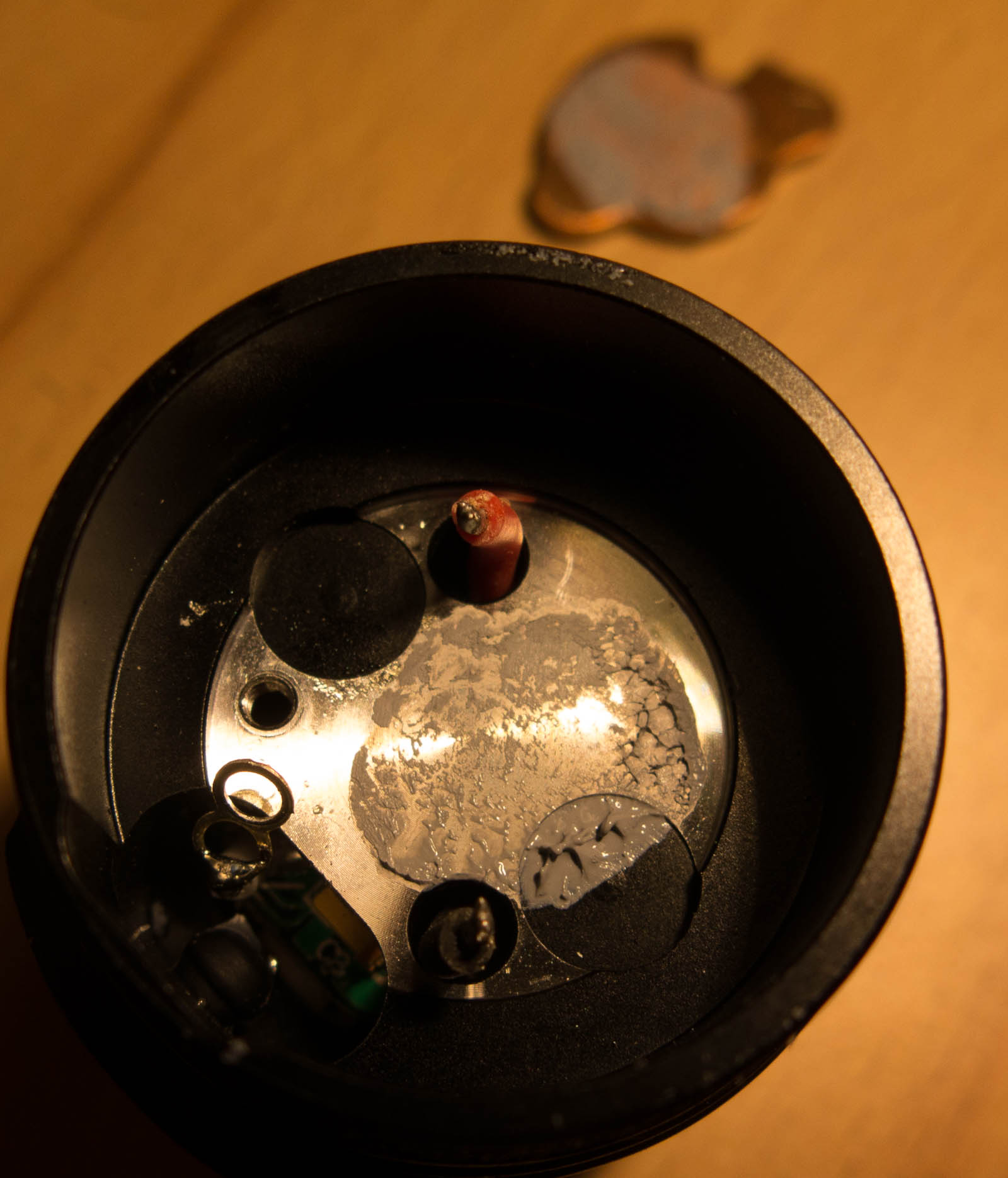
to get the driver section out I needed to lift the side switch retaining ring
it is just pressed in no glue
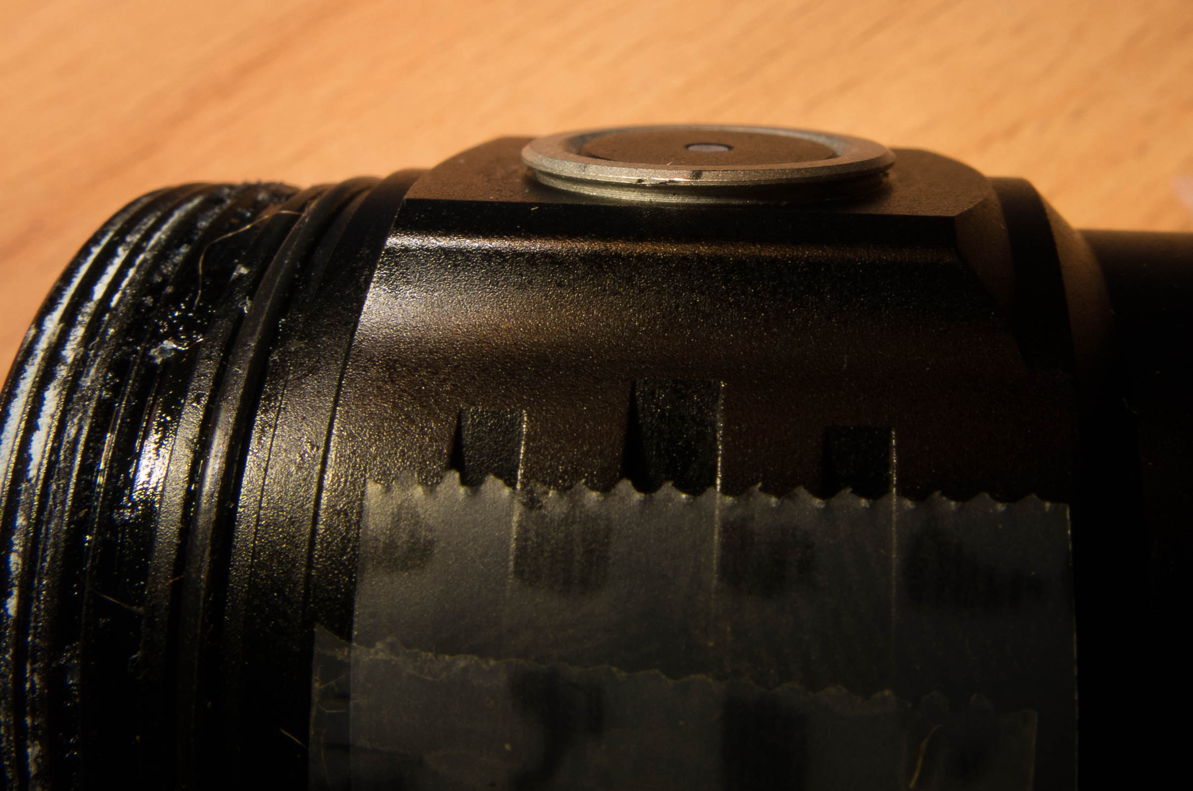
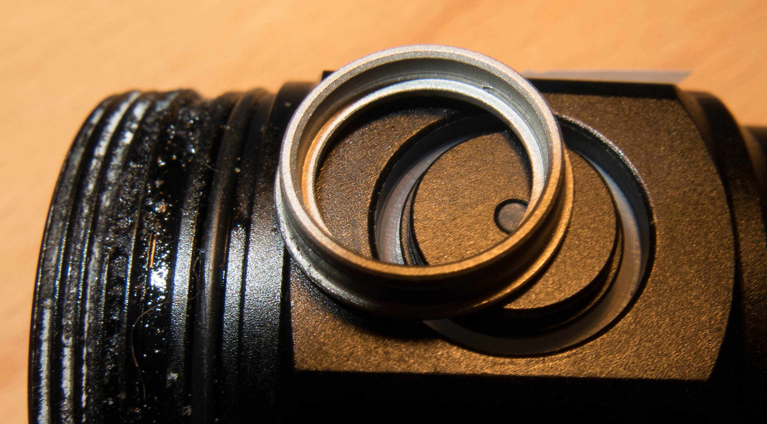
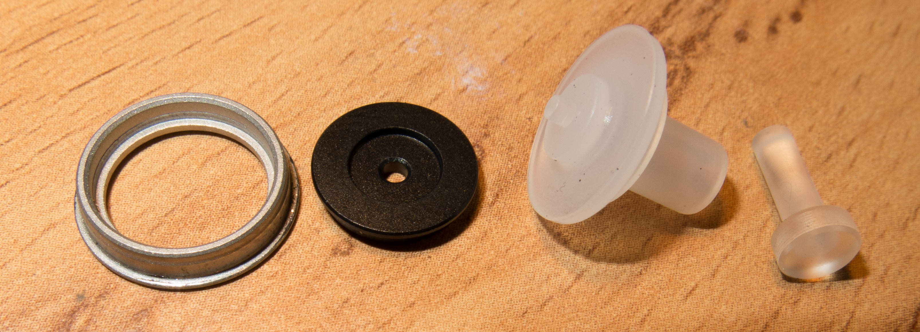
the side switch is made out of 3 parts
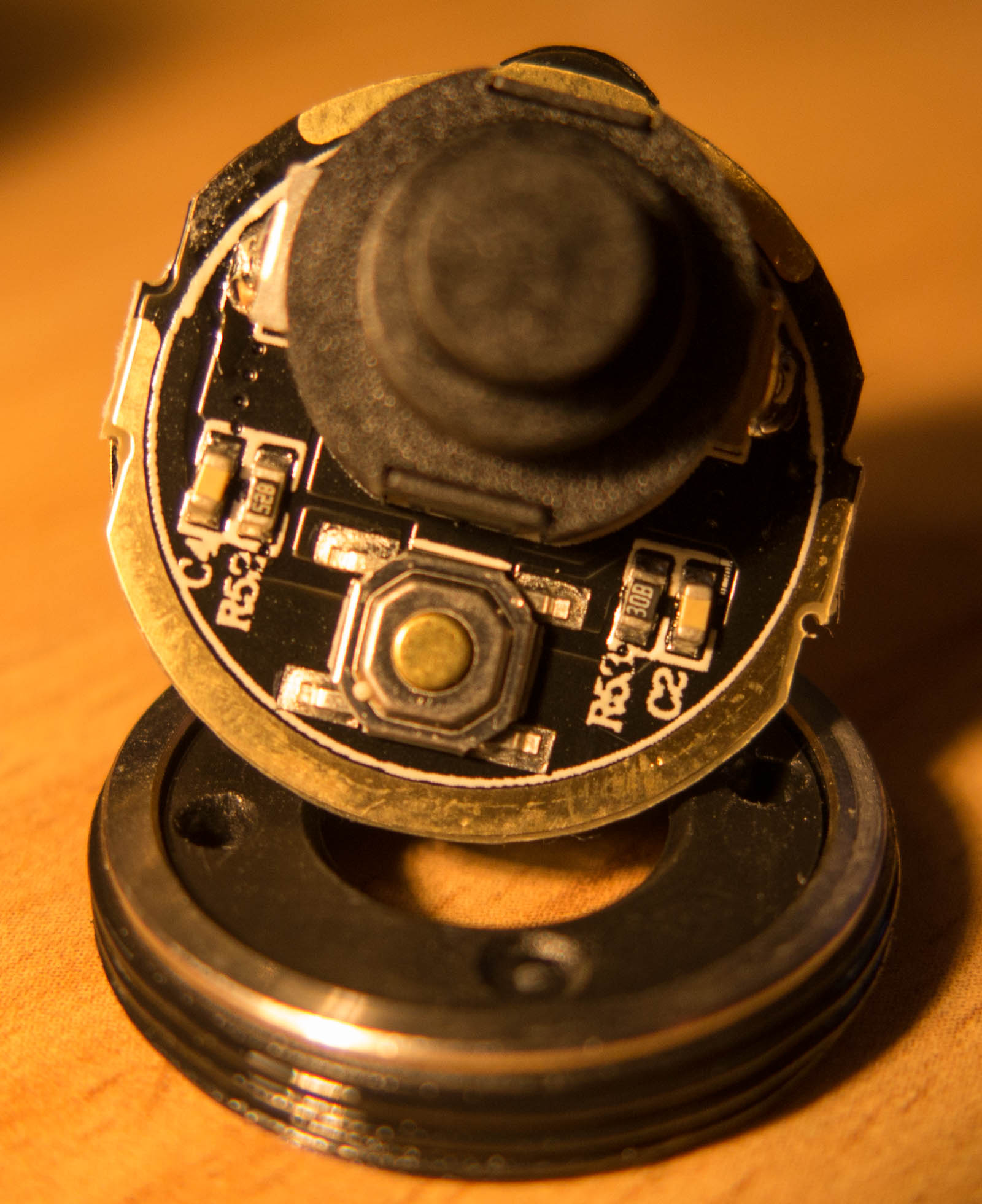
now coming to the driver
The coil is not glued to the driver or other heavier parts so this is not good for mounting on a rifle
I hoped there is a PTC on it I can set with a tunable resistor to a higher case temperature to step down,
but there is no such thing on the driver.
As the driver has not much contact with the body I am puzzled how the monitor the temperature for a good regulation
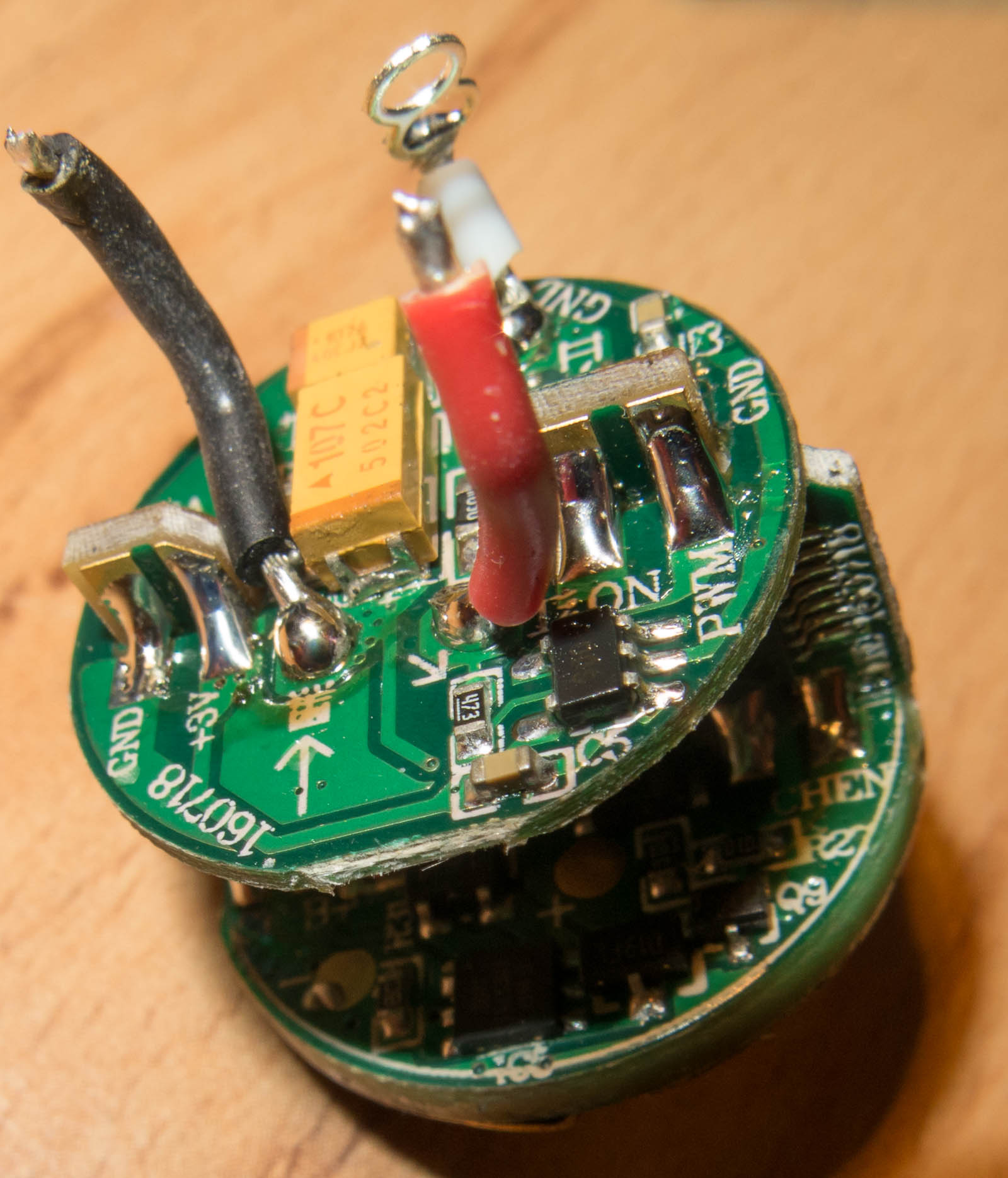
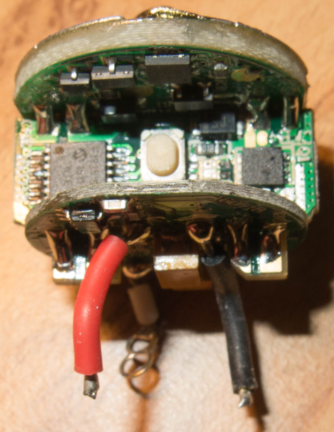
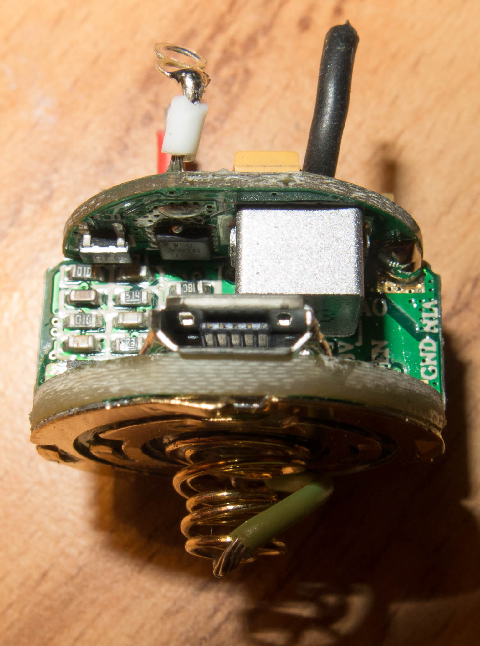
The main microcontroller is a F1825IST TSSOP14
DTQ3205 P-Channel 20 V (D-S) MOSFET
WSD3050DN N-Ch MOSFET 30V 7mΩ 50A
PDS1040L 10A LOW VF SCHOTTKY BARRIER RECTIFIER
3.3uH inductor
2 shottky diodes CDBW120-G
tons of capacitors, resistors and some transistors
there is an 1.2A EMC5755 Standalone charging circuit on the driver
for current monitoring it uses a 0.05 Ohm resistor
