There are two different boards and two different narratives going on in the same post?, I think that’s the problem. My comments related to the latest board and the latest comment from post #89 which said:
So sorry for my confusion, this is an SST only driver then. I did say “non SST color led’s” in my previous post, realizing they can take all that the battery can give to them.
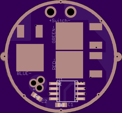
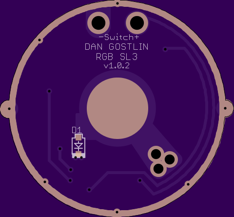
Allright guys first let me explain real quick there are actually 2 different driver projects going on in this thread, the SL-3 SST-90 driver is 22mm (a direct fit for the SL-3 with wings and a mounted switch), that one will run the big DPAK FET’s AOD510’s) direct drive to the SST-90’s off an ATTiny from DrJones (he’s modified his standard RGBW code to substitute what is the white channel for RGB mixed), that project is coming along well but today I worked on my other driver…
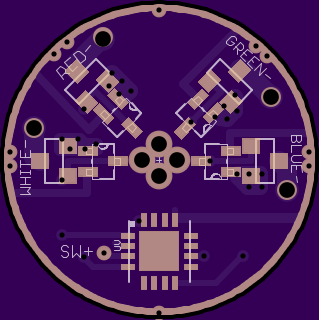
This 20mm driver is a more wide application driver, it runs a PIC MCU provided by tterev3 (he provides us lots of open source code but the MELD is proprietary, thats understandable), each individual channel can have its level set with the RSET resistors (the 1206’s) and is constant current. This can be used to drive 4 color emitters (or all white emitters if you use your own FW) or an XML Color, max current per channel can be up to the limit of the FET, 4.2A for a 2502’s (and could go up to 5.7A for a AO3400’s but no other color emitters need even the 4.2A from the 2502 so no reason to buy new parts), the other component there facing the FET is a standard BJT.
I plan to use it in applications with both individual RGB XP-E2’ & a white XP-E2/G2 as well as with an XML-color.
Plus there’s the MC-E color but I have no idea its spec’s or anything and it costs just as much as the XML color so probably not worth messing with, I think its pretty low current (and possible an MK-R color but I’m not sure if one exists and I think the MK-R is a higher voltage emitter anyway).
Edit: from blank page/blank computer screen to what’s above in <5hr! I should do this for a living (especially if someone else designs the circuits and I just make the boards, that’s the fun part)
I like the idea of taking control of current with the current sense resistor and a bipolar transistor. Good job.
Is there only one small via carrying all the current from the mosfet to the sense resistor? Put the sense resistor on the same side and right next to the mosfet with a nice large track. The micro only carries small signals, put the micro and small resistors on opposite side.
No more electronic switch?
Still no fan of programming pads, or even vias that are scattered about willy nilly.
1 thanks
2 yes. I really want the sense resistors on the bottom for easier access, I expect it’s going to take a lot of tuning to get the different colors matching in output so that was the reason I choose to put them down there. Do you think I could make it work if I made larger copper pours around the pad’s (out into the open space) and used more via’s? For current carrying is more smaller or fewer larger via’s better?
3 Its there, via just left of pin 3
4, I’ll probably be removing the pad’s, with the FW being proprietary and unreleased I wont be needing to flash these ever, on my other PIC driver in my pukelight I like the via’s with bottom access so I can constantly be making changes. The only thing is this uses a QFN chip so there is no way to add air-wires to the legs if needed. I will probably remove the programming pad’s but add a small extension off pad 2 (the UV channel) and any others Everett recommends for plans he may have to add functionality)
wight- had a quote/reply in my clipboard to add here but copied over it- No idea on a name but the circuit is the same one used in the tiniest10’s and is described in detail here. Page 6 has a wright up of this exact one with the math. It looks like from the instructables comments its used in a pretty wide range of applications.
DrJones- does that mean .6 x 4 (.6 per channel) or .6v total? Will the red LED’s lower vF help counteract that any overall? What about 4.35v cells? What about parallel cells? What are we talking here, no light, dimmer than it should be, not able to reach full current, worse?
.05 I know your a pic guy, is it ok to ground pin13 threw the main base pad of the chip (and then ground that) or does pin13 (VSS) need its own trace direct to ground?
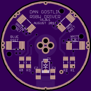
changes include:
more via’s from sense resistor to FET’s source leg’s
LED-’s made into via’s, notice the mask covers the bottom to help prevent shorts when hooking from the top but can easily be scraped to hook from bottom
programming pad’s gone
GND ring via’s added
small extensions of GND pad (13) and UV channel (non_PWM) output for possibly use later (need scraped)
other minor tweaks and silkscreen changes.
0.6V for each channel individually. It will be dimmer than it should be, except for red (low Vf). 4.35V cells, parallel cells, good contacts with low contact resistance, and cells with low sag under load may help, but even then it won't stay regulated for long. I don't know discharge diagrams for those cells, but you'd need 4.2V+ cell voltage under load(!) to fully drive green, not even counting contact resistance.
AMC7135s have a drop-out of 0.12V - there's a reason why we like them.
Pretty sure the PIC DFN center pad is neutral, so O.K. to connect to ground pin and B- from there.
Via’s are kind of sketchy in terms of copper weight which is why I suggested same side as the fet. Might be some formula for current carry capacity per hole size. I would go small if I could get solder to them, maybe medium if not, no real figures or facts to back that up.
I see the .6V drop that Dr. Jones is talking about in the main current path. Is there ultra low base emitter voltage type transistors like from Diodes or Zetex? I have to think that the AMC7135 operates off of a similar principle.
The AMC7135 is much more complex, it contains a band-gap reference, a current sense resistor, an operational amplifier, a FET, some resisitors and capacitors.
Edit: Oh wait, there are such transistors: germanium transistors, about 0.2V, but they have disadvantages. And I have difficulties finding them in SMD.
Thanks Cereal_killer. The operation of the circuit makes sense. Isn’t this CC circuit putting the FET into a special, partially turned on, state? I guess that might be triode region. Does the FET need to be derated or anything for that? I think with a hard driven red XP-E2 you can definitely exceed the dissipation spec of an IR2502, even without derating. Seems like you might want to pot or heatsink this thing.
To add to the responses of others in regards to drop out, it’s on a per channel basis as stated and here’s how you figure it (or at least how I figure it):
Vin - Vdropout > Vf
As long as this is true then there’s no problem. If Vf is lower than Vin minus Vdropout we have problems.
They are definitely good stuff. Sometimes I wish I could customize their behavior a little though. Eagle doesn’t always make the most attractive things with polygon pours. Especially when you make two pours fight it out, even with the Rank parameter in use.
I’ve said it before that I’m not the one to ask about the circuit stuff but from my VERY LIMITED understanding of it its the BJT that runs in partially on state.
Would adding a inducer (toroidal or normal) inline with LED+ (or anywhere else) be beneficial?
So how does that math work? Do I just use the highest emitter’s vf or do I average the vf’s of the 4 or calculate a % of drop per emitter or what?
I could be misunderstanding what happens, but I’m thinking that they both run in the partially on state.
I don’t think an inductor would do much for us here - you don’t have space for any large ones anyway.
You need to break things down for the math, keep it simple. Your emitters have nothing to do with each other, think about it. Why would one care what the Vf of another is? They are not connected to one another. Same thing with the CC circuits - they do not connect to each other at all, therefore you may ignore three of them when doing the math for any individual one. The battery voltage will be the same for all of the circuits since they all connect to the same battery. If the cumulative stress of everything that’s hooked up to the battery causes the voltage to drop then you’ll have to consider that when doing the math, regardless of which circuit you are looking at.
Here’s a sanity check for you: White probably has the highest Vf by a little, so therefore it will drop out at a higher battery voltage. Red has the lowest Vf by far, therefore it will stay in regulation until some lower voltage than white.
Just got some great news from the good Dr, the modified (white channel omitted, modified to use RGB in place of white) FW is ready. Because its also DD (and well anything other than 2x7135 per channel) he also left out the cell resistance / capacity function. Sounds great!