voltage drop between the driver and the led, (grounded on the tailcap). losing 30mV in the wires, not enough to make any difference in visual output?
Also looks like positive (red wire) are directly connected to the leds ( got 4.2 v on the positive side of the LED even when the light was switched off )
got 3.92V on the LED I tested, but this was with the negative lead of the DMM connected to the tailcap.
Going to measure current to LED tomorrow.
30mV is not a big deal. can be ignore
that driver is a buck driver.
its a low side switching driver.
measured to 1.83A @ the LED. any point in resistor-modding this?
(XLM-T6 driven at 1.8 amps should give something like 650 Lm . 650*3=1950Lm. connsidering loss in DMM-cables its probably 2 amps pr LED witch should give roughly 2100-2200Lm )
^
Another Norwegian! ![]() God kveld…
God kveld…
What is the max someone have pushed their light with resistor mod and what resistor/resistors were used?
Im considering to buy one…
I think 3A is more than enough for this flashlight, Remember that more heat also means less light, so if it heats up faster it would be worse for light output and battery duration.
Powahh… MOAARR… ![]()
According to this graph you will get about 12% more light if increasing led voltage from 3A to 4A (33%).
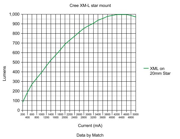
That does not sound impressive considering the heat issues. But still it is more…
This graph on the XM-L U2 (one bin higher compared to T6 I believe was used in previous graph) is a bit more optimistic when going beyond 3A to the led. About 18% increase in light output up to 4A.

But same led on cooper star and things start to get “naughty”… Generally higher output and 20% increase up to 4A according to the graph

3x XM-L2 T6 3C on cooper stars inside skyray king@4-5A… Then we are talking about some high class porn flashlight… I could settle with 4A, but would probably not mind 5A… 0:) :heart_eyes:
On top of the extreme ouput I could also use it as a hand warmer when cold outside.
I got the graphs from this thread, and user “match” basically confirms they are pretty accurate with his testing too.
God this is fascinating, where can I get the extra resistor to solder on top of the 153 please ?
I’m replacing whatever is in my FandyFire UV-S5 with the U2 T6’s, if I did this without the resistor mod would it still be better ?
Do people on here use light metres to test output, and if so what is a good one to use ?
Thanks
tabs
going from 2 to 3 amps (675 to 875 Lm pr LED) will increase the total lumens with just 600. (2025 to 2625) so I am not sure it is worth it, have anyone tried the resistor mod? any beamshots? I am getting another SRK this weekend, and if nobody turns up with beamshots, I will do the mod to one of them just to test it and report back.
http://postimage.org/gallery/9ymtec8o/
Click to enlarge each picture, click again to download original resolution.
Look at the text, they are different versions.
OLD (First Gen) [Ordered on 21th Feubrary 2012 at Lightmalls]
NEW [Oredered December 27th 2012 at ManaFont]
It's not an even comparison, they are sightly different from the outside, and the modded one also has better LED BIN. But something is something at least.
Bump, I’m itching to get modding, what wattage resistors do I need, I have a local maplins store close by.
Please help from one nutter to another, thanks,
tabs
FX-32, thanks, but I can’t find them in my Maplins book, I was going to use the add a resistor rather than unsolder the existing one, they just quote them in 1/4 watt, 1/2 watt etc and the resistance, that’s why I’m confused.
tabs
then you can add 39K resistor parallel with exiting 15K resistor. which make around 10K parallel resistance.
1/4w,1/2w or 1/8w any. better if it smd (805 size) so you can solder easily.
The existing resistors are 0603 size. If you are going to parallel another resistor on top, it is easier to do if you use the same size. The 0805 size will hang over the ends of the existing 0603 resistors and may be tricky to solder. Beware: 0603 resistors are tiny, Tiny, TINY little buggers.
The power rating of the resistor in this application does not matter. In the circuit that they are in they dissipate virtually no power.
But aren't these the sense resistors? In the past you said all of the current went through them? 
No, the SRK has amplifiers (LM358 op-amps) on the sense resistors. The resistor change we are talking about just changes the gain of the amplifiers.
oh my bad. I mean same size as exiting resistors. I thought it was 805.
These resistors are for gain setting of LM393 OpAmp. there is a current sense resistor too. it 0.01 ohm resistor. Drive current can also increase by reducing that 0.01 ohm sense resistors with parallel same value. but I think its bit difficult to find 0.01ohm resistors.
There are 3 sense resistors present.
That’s true ![]()
[click to enlarge]


I can’t find the 0603 easily, so will go with the std 1/4w jobbies from my local hobby place, thanks for the advice I can get modding now.
Just one other thing is it possible/easily to slow down the strobe rate, I suspect not as assuming that is “set” by a chip ?
thanks
tabs