So why, then, are the rectangles so dark in this picture?
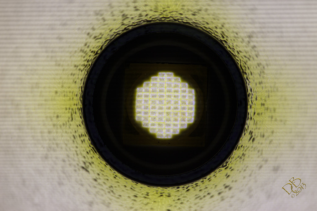
No welders lens, an 8000th of a second shutter was used.
So why, then, are the rectangles so dark in this picture?
No welders lens, an 8000th of a second shutter was used.
If I take a royal blue XML2 and a neutral 5000k 3C XML2 and shine them at the same spot on the wall, I get a cool white spot that looks to be around 7000k. It looks like one cool white LED, not a mix of two very wildly extremely different color LEDs. That's what you have now, some light around 5000k and some royal blue light. Doesn't that square up pretty solidly with the changes you see in the tint?
What other explanation could there possibly be? There's no phosphor on the tops of the dies. There used to be phosphor on top of the dies. The tint used to be neutral/warm white, it is now cool white. Are those things not related?
The Texas Poker was thrown in for chits and grins, a 10440 light pulling .80A on an Nichia 5000k 219. The Elektrolumens Triple XM-L2 U2 is running direct drive on a 26650 pulling 6.62A. The S2200 is modded with resistors and is pulling 2.53A. The K3 is de-domed, direct drive, pulling 6.52A The red oil drum is 97yds away, the house is 42yds, the central area of the drive lit up by the little TP is 25yds. The camera is zoomed in to a 112mm equivalent. Or roughly 2 times larger than what the eye sees. (we see about the same as a 50-60mm lens focal length) Canon G1X at standard settings of ISO1600 F/5.8 .5 second exposure.
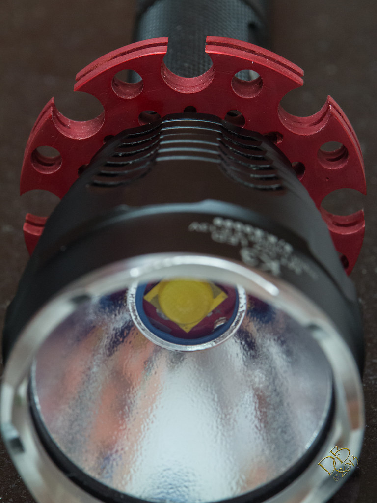
I would fully understand the math if the light coming from the de-domed MT-G2 emitter was actually cool white. Anywhere near the XM-L2 U2 or XM-L U2 and it’d make perfect sense. But look at the color this thing is putting out. That’s pretty much exactly what it looks like, lavender. Doesn’t matter whether it’s got the TIR on top of it or the stock reflector.
And yes, I saw the pics of your de-domed MT-G2, royal blue it is! I’m not arguing, just puzzled at the color this ones making.
Really isn’t fair to put that Texas Poker in with these guys, is it? lol Being as how they’re 2500-3000 lumen monsters and it’s so cute and cuddly. ![]()
Well obviously it would depend on how much output comes from the phosphor-free area and how much comes from the phosphor adjacent to the dies. In my comparison the royal blue XML2 is using a leftover driver from a Manafont dropin at something like 2.3A, and the NW/5000k is direct drive. If those currents were swapped it would be significantly closer to a purple/lavender than traditional cool white.
One of these days I will quit procrastinating and pick up some of the smaller minimum-quantity pieces from here: link
Pulsed air cooling fins, 12 bucks. Oh you shouldn’t have! ![]()
How much blue light or how intense is the light coming from that MT-G2 of yours with no dome? Is it anything like what a “black light” does? Or a UV led? I will probably order a new emitter and change this one out, am thinking of scraping all the phosphor off and seeing how it runs under the TIR optic. You know, just cause!
And yeah, I know, DO NOT LOOK at it!
First I’ll see what a Lee filter will do for color tint, might just run it corrected since it makes so much lumen output (filter robs a percentage)

LOL, Thanks…I couldn’t remember where you posted a pic of that emitter. Looked for it, failed to find it. I’m in the process of swapping the factory emitter onto the Noctigon board. Well, just did that and everythings cooling before I solder new wires and put the 4A driver back in. Will clean the phosphor off this die while on the Solarforce board and find a way to mount it for scorpion hunting. ![]()
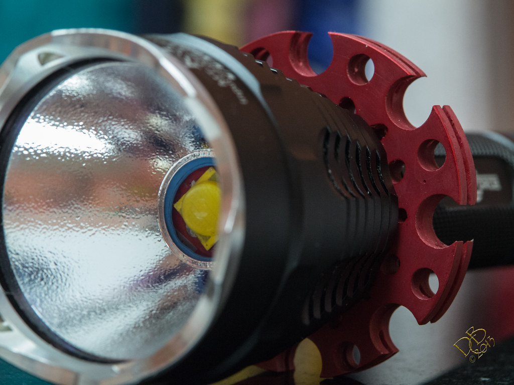
That bright yellow zip tie is actually a nice deep green. And the camera is really unhappy trying to take pictures of this evil thing.

What I'm curious about is if it'd be possible to cut a small piece of that remote phosphor stuff, just big enough to cover the die, and get a reasonable output from it. Even if it won't work to save these mutilated MTG2s it would still be fun to play with.
and of course thought the same thing! It would be interesting. Wonder if it has to be tied/glued down? Hmmmm……
I put the MT-G2 from the Solarforce pcb on the Noctigon pcb and fixed the copper heatsink so it could take the QLite driver without causing issues. I’m back to 4.05A on Hi, 1.14A on Med and .08A on Lo. Much more sane to run the K3 and the copper sink should work better at this level as well.
The offending MT-G2 is daid. Binned and all but in the landfill. I did keep the 32mm copper disc that was in the Solarforce as a pcb, but with the circuitry removed.
Glad you found an output level you’re comfortable with and the light can handle. It’s the alterations made to stock lights that I find most interesting and the pill and collar for your K3 are right up there.
You hardly see any lights with a 45mm TIR optic, I was really liking that…made it pretty unique along with the other things. But now that I have a standard MT-G2 I can’t use the optic as it’s made for a much smaller emitter.
I think the 2330 lumen neighborhood will be much kinder to this smallish light. Still plenty bright! ![]() Think I’ll dunk the collar in an acid bath and clean it up, try the anodizing again with pure red. See if I can get it nice and dark red to go with the black. Always something, isn’t it? lol
Think I’ll dunk the collar in an acid bath and clean it up, try the anodizing again with pure red. See if I can get it nice and dark red to go with the black. Always something, isn’t it? lol
I reworked the heat sink. No more brake rotor. I turned locator lines to enable me to relocate the outer holes a bit, enlarged the 2 larger sizes and then turned it down such that the 5/16” diameter holes were cut off, making an anti-roll feature as well as giving some self-defense properties to this light. And it looks cool! ![]() I then filed/sanded acid etched, anodized and re-dyed it a deep dark red. This is pretty much where I intended to go in the first place. And with my crapola extreme drill press, I still got the holes off a bit…tried very very hard not to! Oh well!
I then filed/sanded acid etched, anodized and re-dyed it a deep dark red. This is pretty much where I intended to go in the first place. And with my crapola extreme drill press, I still got the holes off a bit…tried very very hard not to! Oh well!
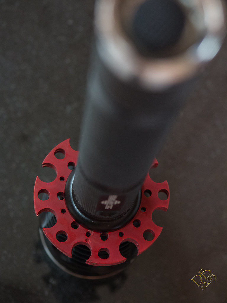
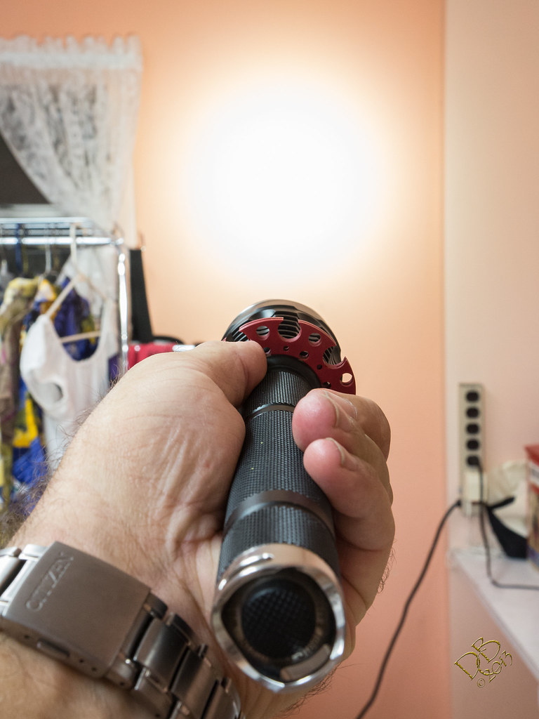
The final diameter is 2 3/16”, pretty close to the size of the head. The points are fairly sharp, even though I did file em down a bit. The light is pretty intense, this room is one of the brightest in our house, about 10x12 with 2 4’ HO T5 fixtures strung end to end. I’m going to leave it alone now. ![]()
As it might be of help to someone, I thought I’d add something about some little details that were needed when I added the heatsink. I already had the copper heatsink/pill sized to fit into the light sans external sink. So, putting this quarter inch piece of aluminum between the head and host means the pill doesn’t fit, right? I needed a spacer, something that would let the copper pill still transfer it’s heat into the heavy part of the head. I had gotten some SinkPADs from Vesture and also from Nitro. When you get a sheet of pads, they’re usually all together…15 on a sheet with a border around it. I used the quarter inch strip that ran along the top to make a copper ring to fit into the head of my L2P. Sanded off the dielectric layer and bingo! Perfect fit! ![]()
Ok, that’s all well and good but now the batteries go too far into the tube and the tailcap can’t make connection, not to mention I added a McClicky in the tailcap so it’s a bit shorter anyway. I cut a piece off a bar of 1/2” 6061 aluminum to bridge that gap. Before I cut it completely off the bar I cut a groove into the middle of it…to hold an o-ring. So now it will sit on top of the negative end of the 18650 and the o-ring keeps it from making the connection and bypassing the switch. Nice little aluminum spacer with a black o-ring belt. ![]()
So now you know the rest of the story! ![]()
I was curious about the output on the S2200 after stacking the resistors. I know the tailcap amperage went from 2.10A to 2.53A, but the light seems much brighter than that indicates…and the heat starts much faster!
So tonight I measure the forward voltage at the emitter. And here’s where I get confused all over again. The S2200 with it’s 3 18650 cells is pulling 2.53A at the tail, the K3 with it’s 2 18650’s is pulling 4.05A at the tail. BUT, they both have the same Vf! 6.35Vf on each of them. So how can amperage show almost half, but Vf be the same? I must be missing something, somewhere!
What’s that formula for figuring watts again? Almost makes me willing to pull the negative lead on the S2200 and get an emitter amperage reading, but the last time I did that the numbers were argued to the point that it wasn’t worth it.
With 3 1R00 resistors stacked and the 4th stock resistor left alone, what would happen if I stacked on the already stacked resistors? Just … one … more …
You may be fine, as the MTG2 seems unkillable with amps/volts alone. I only know it'll zap a XML when the driver gets unhappy with your choice of resistors.
Wattage is volts x amps. To find out if the excess current is being eaten by the driver you have to measure both in and out current + voltage and convert both to watts, then compare. The input wattage needs a measurement of the input voltage under load, not just while the cells are at rest.
Current being amps? Current at the tailcap being in, current at the emitter being out?
Do you think the 6.35Vf on both lights is odd, having such different tailcap amperage numbers? I’ve never understood the low tailcap readings on the S2200, with the power it makes.
Yeah, I can see 3 cells killing an X series pdq if allowed through the driver. The MT-G2 is only killed by overindustrious sorts like me. lol
As an estimate (real numbers are better) say the 3 cells in the S2200 are at 3.9v under load, and there's 3 of them, so total input voltage is 11.7 volts. Input current is 2.53 amps. 11.7 x 2.53 = 29.6 watts.
29.6 watts divided by the measured Vf of 6.35 gives an amps at the LED of 4.66 amps, which sounds about right compared to the driver output I got with the S1100 driver after resistor mods. Remember mine started with 2xR220+2xR240, yours started with 4xR220s (lower total resistance = higher output current), and I ended up with an output of around 4.3A.
Measuring amps at the driver output will get rid of the guesswork, but these numbers sound plausible.
edit: No circuit is 100% efficient so there will be some amount of mismatch between the input power & output power.
I knew that the Vf came into play somewhere in the math but couldn’t for the life of me remember how that worked! I knew that VxA=W but also had seen the Vf come into play before. And that 4.66A is about how the light acts, the brightness level, intensity, and the amount of heat coming into the pill area after start-up.
Thank you, that clears things up immensely!
Edit: For the record, after some careful and deliberate wiring up and testing I find that the rack of cells (Protected AW 2600mAh) with a start point of 12.10V drops to 11.27V when the light kicks in on hi. So, with the correct actual Vf of the emitter at 6.37Vf the math will show 4.476A going to the emitter absent any driver inefficiencies and this seems pretty much spot on with the visible results of this light. I don’t think I’ll be doing anything else to this one as I very much like it right where it is! Thanks again for clarifying the equations and reasonings.
Edit II: Curiosity got the better of me, Samsung 20Rs only sagged to 11.98V from 12.37V start, for a total wattage of 30.3094W and an emitter Amperage estimated at 4.758A! The Samsungs really do make a difference, even in the S2200, or maybe especially so? ![]()